Weekly assignments
- week 1. Project Management
- week 2. Computer Aided Design
- week 3. Computer Controlled Cutting
- week 4. Electronics Production
- week 5. 3D Scanning and Printing
- week 6. Embeded Programming
- week 7. Computer Controlled Machining
- week 8. Electronics Design
- week 9. Output Devices
- week 10. Mechanical design & Machine Design
- week 11. Break & Midterm Review
- week 12. Input devices
- week 13. Moulding and Casting
- week 14. Networking and communications
- week 15. Interface and application programming
- week 16. Wildcard week
- week 17. Applications And implications
- week 18. Project Development
- week 19. Invention, Intellectual Property and Income
week14. Networking and communications
Group assignment:
Individual assignment:
design, build and connect wired or wireless node(s) with network or bus addresses and a local interface.Part1 Research
Wired Asynchronous Serial Communication
Data is transmitted in units of individual characters. Each character has a start bit and a stop bit to mark the beginning and end of the character. No clock signal is required to synchronize the sending and receiving devices, so the requirement for clock synchronization is relatively low. The transmission efficiency is relatively low because the start and stop bits add additional overhead. Common asynchronous serial communication standards such as RS-232.
RS-232:
Communication mode: Full duplex, allowing simultaneous sending and receiving of data. Electrical characteristics: Uses positive and negative voltages to represent logic 1 and 0. Usually, -15V to -3V represents logic 1, and +3V to +15V represents logic 0. Transmission rate: Relatively slow, generally below 20 kbps. Cable length: The communication distance is short, usually not exceeding 15 meters. Application scenarios: Commonly used to connect computers with modems, serial port devices, etc.
Wired Synchronous Serial Communication
Data is transmitted in units of data blocks. The sending and receiving devices are synchronized by a shared clock signal to ensure accurate data transmission. There are no start and stop bits, and the data transmission efficiency is higher. Common synchronous serial communication standards such as SPI, I2C, etc.
SPI (Serial Peripheral Interface):
Communication mode: Full duplex. The master device and the slave device can send and receive data simultaneously. Electrical characteristics: Uses a separate clock line to synchronize data transmission. The data line can be uni-directional or bi-directional. Transmission rate: Fast, which can reach tens of MHz or even higher. Cable length: Relatively short, usually used in board-level communication. Application scenarios: Commonly used to connect microcontrollers with sensors, EEPROM, ADC and other peripherals.
I2C (Inter-Integrated Circuit):
Communication mode: Half duplex. Data can only be transmitted in one direction at the same time. Electrical characteristics: Communicates through a serial data line (SDA) and a serial clock line (SCL), and supports multi-master and multi-slave architecture. Transmission rate: The speed is relatively slow in standard mode, and increases in fast mode and high-speed mode. Cable length: Generally suitable for short-distance communication. Application scenarios: Commonly used to connect microcontrollers with various integrated circuits, such as EEPROM, real-time clocks, etc.
Wireless Networking Protocol
It is usually based on radio waves for data transmission and does not require physical wires. It is greatly affected by environmental factors such as interference, distance, and obstacles, which may lead to signal attenuation and transmission errors. Protocols usually include error detection and correction mechanisms to deal with the unstable transmission environment. For example, Wi-Fi, Bluetooth, Zigbee, etc., they have different characteristics in terms of transmission rate, coverage range, power consumption, etc.
Wi-Fi:
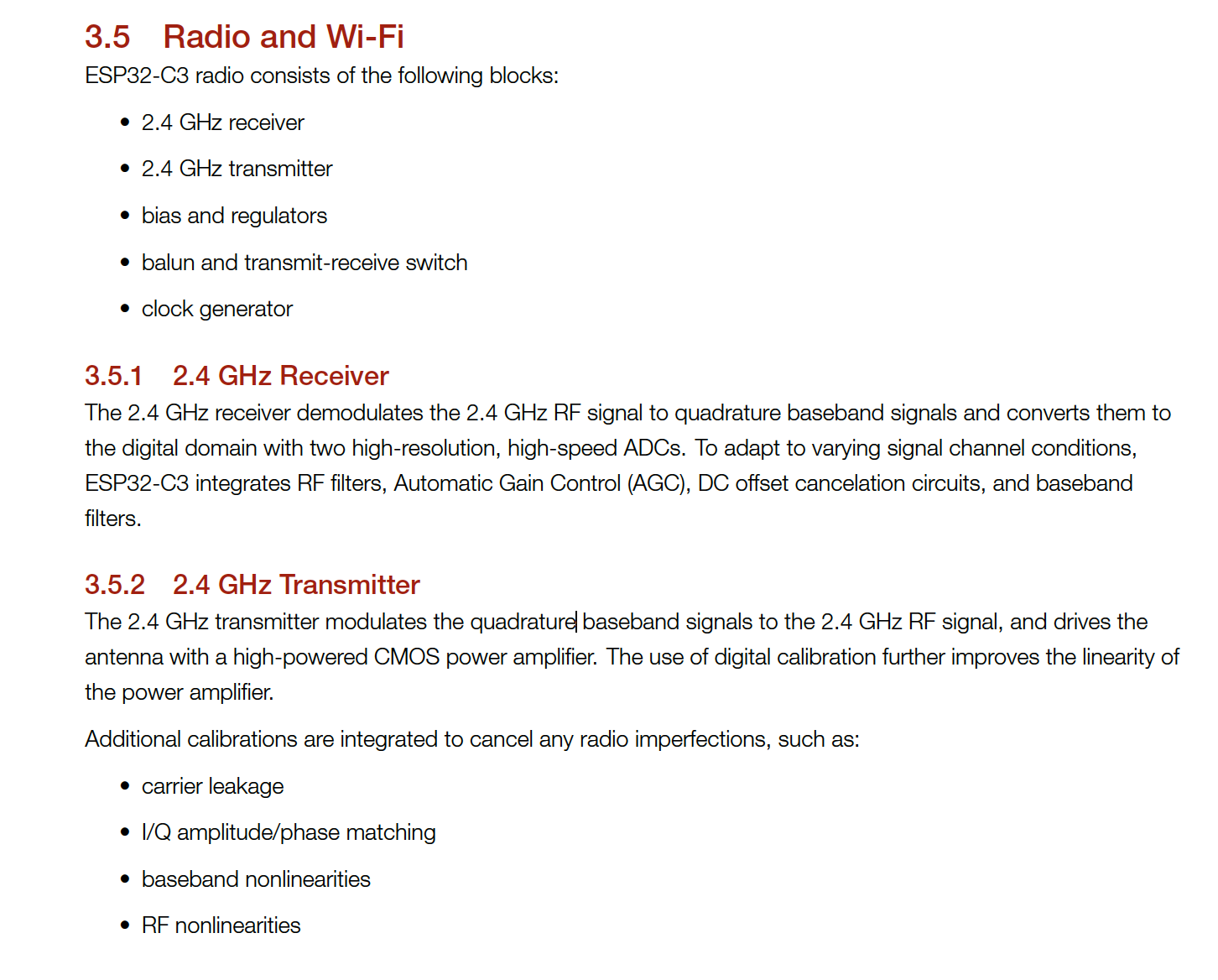
Communication mode: Full duplex, supporting simultaneous sending and receiving of large amounts of data. Frequency band: Usually works in the 2.4GHz or 5GHz frequency band. Transmission rate: High, ranging from tens of Mbps to hundreds of Mbps. Coverage range: Depending on power and environment, the coverage range can reach tens of meters to hundreds of meters. Application scenarios: Mainly used to enable devices to access the Internet, such as the connection between smartphones, laptops, tablets, etc. and wireless routers.
Bluetooth:
Communication mode: Supports both full duplex and half duplex. Frequency band: Mainly works in the 2.4GHz frequency band. Transmission rate: Relatively low, generally between 1Mbps and 3Mbps. Coverage range: Short-distance communication, usually about 10 meters. The coverage range of Bluetooth 5 and higher versions has increased. Application scenarios: Commonly used to connect mobile phones with headphones, speakers, keyboards, mice and other devices for short-distance data transmission and control.
Zigbee:
Communication mode: Supports various network topologies such as star, tree and mesh. Frequency band: Usually works in the 2.4GHz frequency band. Transmission rate: Low, generally about 250kbps. Coverage range: Tens to hundreds of meters, depending on transmit power and environment. Application scenarios: Suitable for low-power, low-data-rate Internet of Things applications, such as sensor networks in smart homes and industrial control.
Part2 Group Assigment My Part
Our group used XIAO ESP32C3 board connecting to the DHT11 temperature and humidity sensor and one XIAO ESP32C3 board connecting a LED.
One ESP32C3 is sending data over WiFi and another ESP32 device receiving this data on the same WiFi network, applying HTTP protocol, to complete the sending and receiving.
What I have learned from our group assigment
Sensor Interface and Data Acquisition
Gain an in-depth understanding of the working principle and communication protocol of the DHT11 sensor. Master how to correctly connect the sensor to the ESP32C3 board, including pin configuration and power management. Learn to process the raw data output from the sensor, perform data conversion and calibration to obtain accurate temperature and humidity values.
WiFi Network Configuration and Communication
Become familiar with the WiFi module function of ESP32C3 and the use of related libraries. Learn how to set WiFi connection parameters, such as SSID (network name) and password. Understand the network topology, including the differences and application scenarios of access point mode and station mode. Master the techniques of data packaging and sending, and handle packet loss and retransmission mechanisms.
HTTP Protocol Application
Learn in detail the format and structure of HTTP requests (GET, POST, etc.) and responses. Learn to construct effective HTTP header information, including Content-Type, User-Agent, etc. Master handling HTTP status codes on ESP32, such as 200 (success), 404 (not found), etc., and perform corresponding processing based on the status codes. Understand the roles and responsibilities of the server side and the client side in HTTP communication.
Embedded System Programming
Proficient in the programming architecture and instruction set of the ESP32C3 microcontroller. Learn to optimize the code to improve system performance and reduce power consumption. Master low-level programming techniques such as interrupt handling, timer usage, and task scheduling. Understand the importance and implementation methods of memory management and resource allocation in the embedded environment.
System Integration and Debugging
Learn to integrate each module (sensor, WiFi, HTTP communication) into a complete system and ensure their collaborative work. Master the use of debugging tools (such as serial monitor, logic analyzer) to diagnose and solve hardware and software problems. Cultivate the ability to solve problems such as electromagnetic interference and signal noise that may occur in practice.
Part3 Individual Assigment
This week's assignment is to implement the communication of the chip. I chose to create a web page to complete the communication between the computer web page and ESP32C3.
IMPORTANT! ESP32C3 can only work on 2.4G wifi.
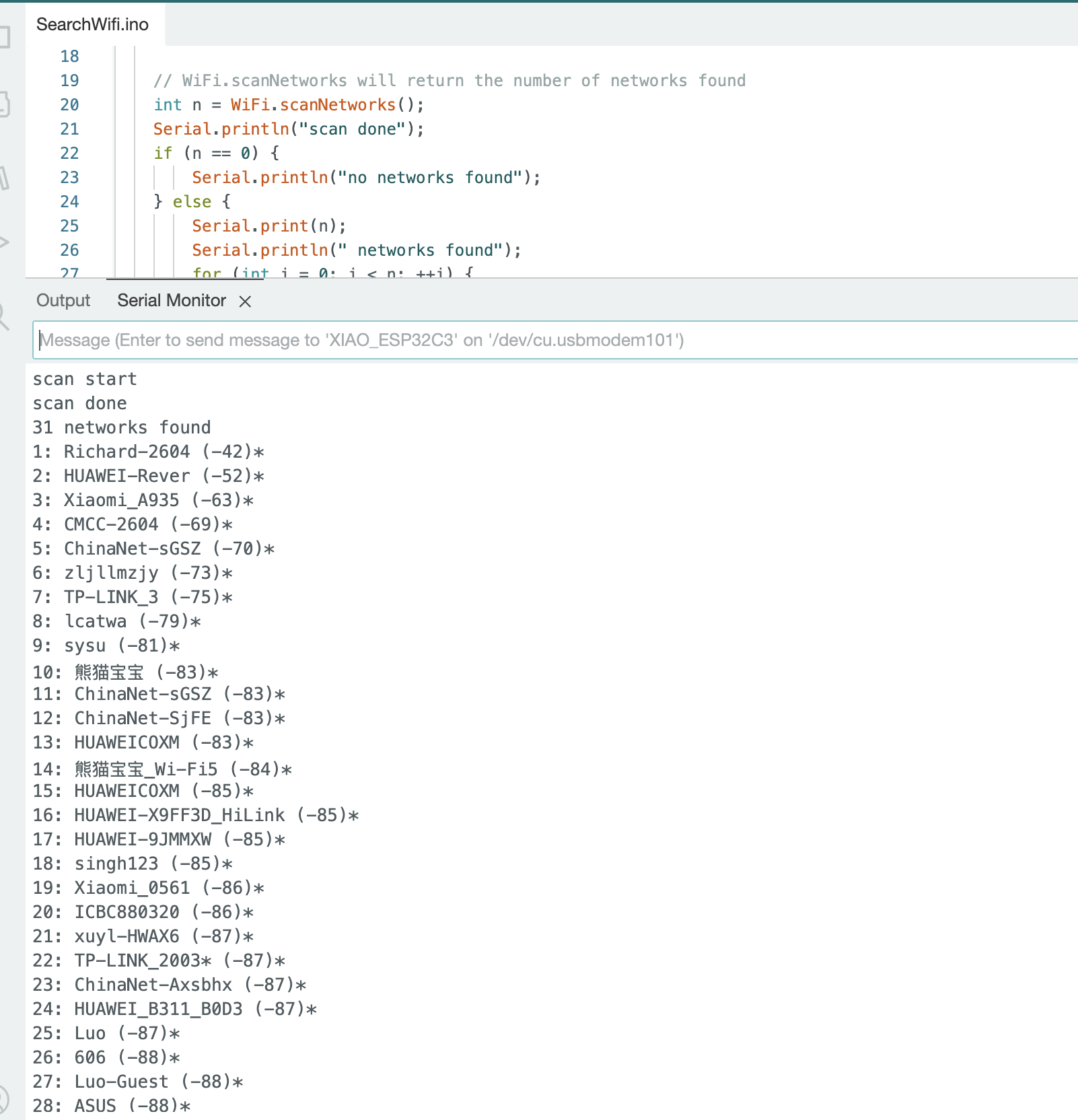
Step1. Scan the Wifi Networks Available.
    #include "WiFi.h"

    // The setup function is called once when the microcontroller starts up
    void setup()
    {
        // Initialize the serial communication at a baud rate of 115200
        Serial.begin(115200);

        // Set the WiFi mode to station mode and disconnect from any previously connected access point
        WiFi.mode(WIFI_STA);
        WiFi.disconnect();
        delay(100);

        // Print a message indicating that the setup is completed
        Serial.println("Setup done");
    }

    // The loop function is called repeatedly after the setup function
    void loop()
    {
        // Print a message indicating that the WiFi scan is starting
        Serial.println("scan start");

        // Call the scanNetworks function of the WiFi library to scan for available networks
        // It will return the number of networks found
        int n = WiFi.scanNetworks();
        // Print a message indicating that the scan is completed
        Serial.println("scan done");
        // If no networks were found
        if (n == 0) {
            // Print a message indicating that no networks were found
            Serial.println("no networks found");
        // If one or more networks were found
        } else {
            // Print the number of networks found
            Serial.print(n);
            Serial.println(" networks found");
            // Loop through each network found
            for (int i = 0; i < n; ++i) {
                // Print the index of the current network
                Serial.print(i + 1);
                Serial.print(": ");
                // Print the SSID (Service Set Identifier) of the current network
                Serial.print(WiFi.SSID(i));
                Serial.print(" (");
                // Print the RSSI (Received Signal Strength Indication) of the current network
                Serial.print(WiFi.RSSI(i));
                Serial.print(")");
                // Print an asterisk if the network is encrypted, otherwise print a space
                Serial.println((WiFi.encryptionType(i) == WIFI_AUTH_OPEN)?" ":"*");
                delay(10);
            }
        }
        // Print a blank line for better formatting
        Serial.println("");

        // Wait for 5 seconds before scanning again
        delay(5000);
    }
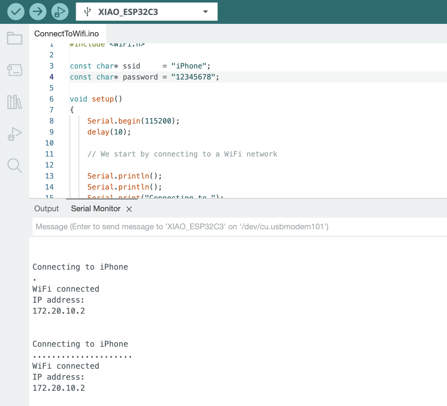
Step2. ESP32C3 Connected to my iPhone's wifi
#include <WiFi.h>

// The Wi-Fi network SSID (Service Set Identifier)
const char* ssid     = "iPhone";
// The Wi-Fi network password
const char* password = "12345678";

// The setup function runs once when the microcontroller starts
void setup()
{
  // Initialize the serial communication at a baud rate of 115200
  Serial.begin(115200);
  delay(10);

  // Print some blank lines for better readability
  Serial.println();
  Serial.println();
  // Print the SSID that the device is trying to connect to
  Serial.print("Connecting to ");
  Serial.println(ssid);

  // Start the Wi-Fi connection process with the provided SSID and password
  WiFi.begin(ssid, password);

  // Keep looping until the Wi-Fi connection is established
  while (WiFi.status()!= WL_CONNECTED) {
      // Wait for 500 milliseconds
      delay(500);
      // Print a dot to indicate that the device is still trying to connect
      Serial.print(".");
  }

  // Print a new line for better formatting
  Serial.println("");
  // Print a message indicating that the Wi-Fi connection is successful
  Serial.println("WiFi connected");
  // Print the local IP address assigned to the device
  Serial.println("IP address: ");
  Serial.println(WiFi.localIP());
}

// The loop function runs repeatedly after the setup function
void loop()
{
}
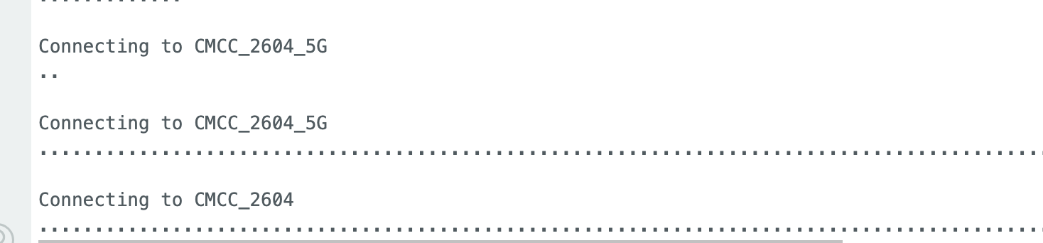
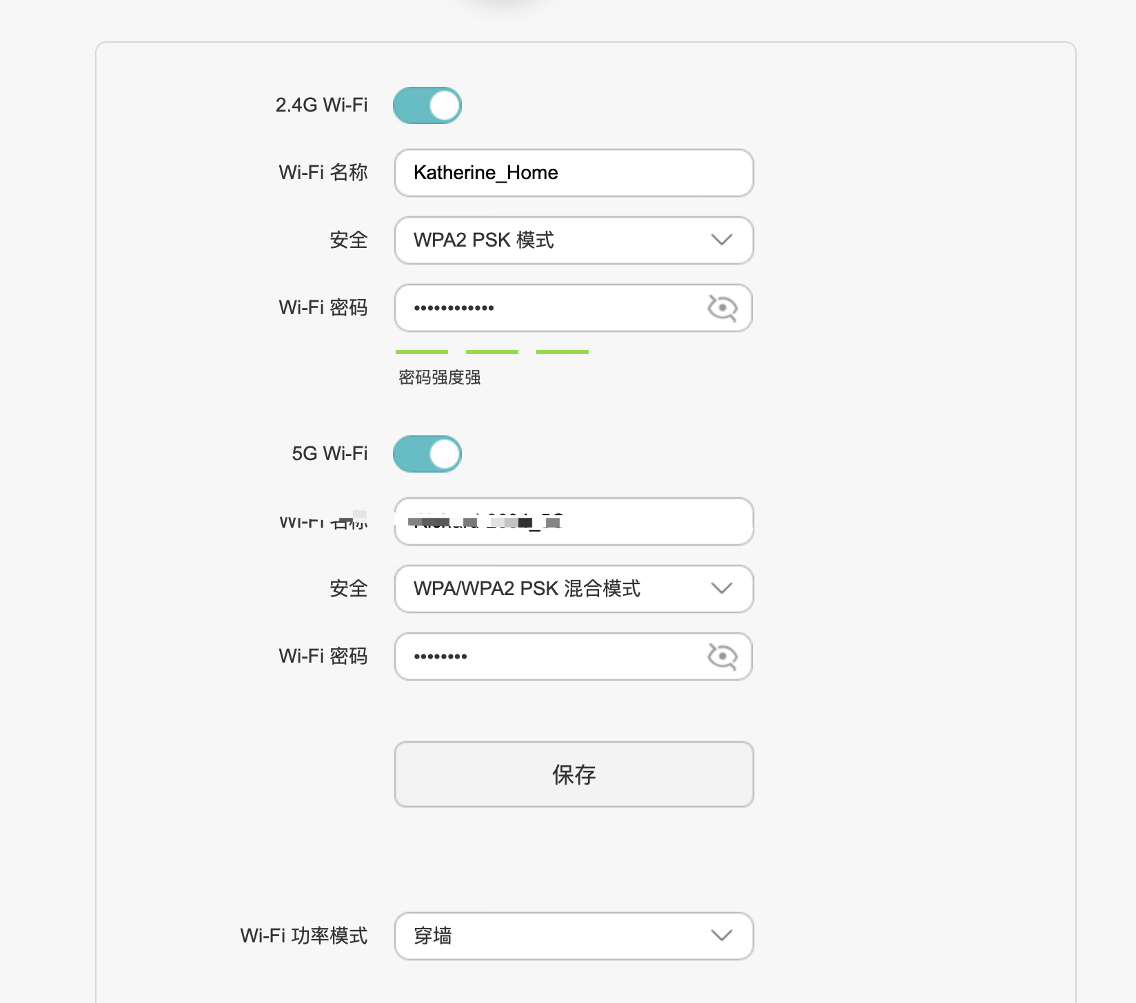
Step3. ESP32C3 Connect to my Home wifi
Step4. Webpage inteaction with ESP32C3 through Wifi
  #include <WiFi.h>
  #include <WebServer.h>

// Define the Wi-Fi network SSID (Service Set Identifier)
const char* ssid = "Katherine_Home";  // Replace with your Wi-Fi network name
// Define the Wi-Fi network password
const char* password = "NiuNiu876519";  // Replace with your Wi-Fi password

// Define the pin where the LED is connected
#define LED_PIN D1

// Create a WebServer object and listen on port 80
WebServer server(80);

// Function to handle the root URL ("/")
void handleRoot() {
  // Create an HTML string
  String html = "<html><head><title>ESP32 LED Control</title></head><body>";
  html += "<h1>Xiao ESP32 LED Control</h1>";
  html += "<p><a href=\"/on\">Turn LED ON</a></p>";
  html += "<p><a href=\"/off\">Turn LED OFF</a></p>";
  html += "</body></html>";
  // Send the HTML response with status code 200 and content type "text/html"
  server.send(200, "text/html", html);
}

// Function to handle the "/on" URL
void handleOn() {
  // Set the LED pin to HIGH (turn the LED on)
  digitalWrite(LED_PIN, HIGH);
  // Send a plain text response with status code 200
  server.send(200, "text/plain", "LED is ON");
}

// Function to handle the "/off" URL
void handleOff() {
  // Set the LED pin to LOW (turn the LED off)
  digitalWrite(LED_PIN, LOW);
  // Send a plain text response with status code 200
  server.send(200, "text/plain", "LED is OFF");
}

// The setup function is called once when the microcontroller starts
void setup() {
  // Set the LED pin as an output
  pinMode(LED_PIN, OUTPUT);

  // Initialize the serial communication at a baud rate of 115200
  Serial.begin(115200);

  // Start the connection process to the Wi-Fi network
  WiFi.begin(ssid, password);

  // Keep looping until the Wi-Fi connection is established
  while (WiFi.status()!= WL_CONNECTED) {
    // Wait for 1 second
    delay(1000);
    // Print a message indicating that the device is connecting to the Wi-Fi network
    Serial.println("Connecting to WiFi...");
    Serial.println(ssid);
  }

  // Print a message indicating that the Wi-Fi connection is successful
  Serial.println("Connected to WiFi");
  Serial.println(ssid);
  Serial.println("IP address: ");
  Serial.println(WiFi.localIP());

  // Set up handlers for the different URLs
  server.on("/", handleRoot);
  server.on("/on", handleOn);
  server.on("/off", handleOff);

  // Start the WebServer
  server.begin();
}

// The loop function is called repeatedly after the setup function
void loop() {
  // Handle client requests
  server.handleClient();
}
This code is for an ESP32 to control an LED through a web server. In the `setup` function, it configures the LED pin as an output, initializes serial communication, attempts to connect to the specified Wi-Fi network, and sets up handlers for different URLs. Once connected to Wi-Fi, it starts the web server. In the `loop` function, it handles client requests. The `handleRoot` function sends an HTML page with links to turn the LED on or off. The `handleOn` and `handleOff` functions respectively turn the LED on or off and send corresponding responses.