Weekly assignments
- week 1. Project Management
- week 2. Computer Aided Design
- week 3. Computer Controlled Cutting
- week 4. Electronics Production
- week 5. 3D Scanning and Printing
- week 6. Embeded Programming
- week 7. Computer Controlled Machining
- week 8. Electronics Design
- week 9. Output Devices
- week 10. Mechanical design & Machine Design
- week 11. Break & Midterm Review
- week 12. Input devices
- week 13. Moulding and Casting
- week 14. Networking and communications
- week 15. Interface and application programming
- week 16. Wildcard week
- week 17. System Integration
- week 18. Applications And implications
- week 19. Invention, intellectual property and income
6. Embeded Programming
Group assignment:
Browse through the data sheet for your microcontroller,compare the performance and development workflows for other architectures.
Individual assignment:
Make and test a microcontroller development boardGroup Assigment My Part
Data Sheet of Seeed Xiao nRF82540
Comparation of nRF82540 with other microControllers:
1. Comparison with Arm Cortex-M series (e.g. STM32):
- Performance: The nRF52840 has a single Arm Cortex-M4F core running up to 64 MHz, while higher-end Cortex-M series MCUs (like STM32) can have faster cores running over 100 MHz.- Peripherals: Cortex-M series MCUs generally have a more extensive set of advanced peripherals, such as more ADC channels, DMA controllers, and specialized communication interfaces.
- Development tools: The Cortex-M ecosystem has a broader range of development tools, IDEs, and debugging options compared to the nRF52840.
- Power consumption: The nRF52840 is designed for low-power applications and can achieve lower power consumption than many Cortex-M MCUs, especially in sleep modes.
2. Comparison with Espressif ESP32:
- Wireless connectivity: The nRF52840 has built-in Bluetooth 5 and 802.15.4 wireless support, while the ESP32 focuses more on Wi-Fi and Bluetooth connectivity.- Architecture: The ESP32 has a dual-core Xtensa processor, while the nRF52840 has a single Arm Cortex-M4F core.
- Power consumption: The nRF52840 is generally more power-efficient than the ESP32, especially in low-power modes.
- Development ecosystem: The ESP32 has a large and mature development community, with extensive libraries and tools available, while the nRF52840 ecosystem is still growing.
3. Comparison with Raspberry Pi RP2040:
- Processor architecture: The RP2040 has a dual-core Arm Cortex-M0+ processor, which is a simpler architecture compared to the more powerful Cortex-M4F in the nRF52840.- Performance: The RP2040 has a maximum frequency of 133 MHz, which is higher than the 64 MHz of the nRF52840, but the Cortex-M4F core of the nRF52840 is more powerful per MHz.
- Peripherals: The RP2040 has a wide range of GPIO, ADC, PWM, and communication peripherals, but the nRF52840 has more advanced wireless connectivity options.
IndividualAssignment_Embeded Programming
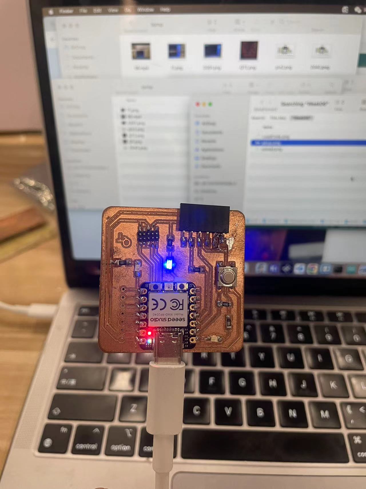
For this assignment, I will use the QT board I made on Week4 to do the embeded programing with RP2040 using arduino.
1. Seeed Xiao RP2040 Introduction
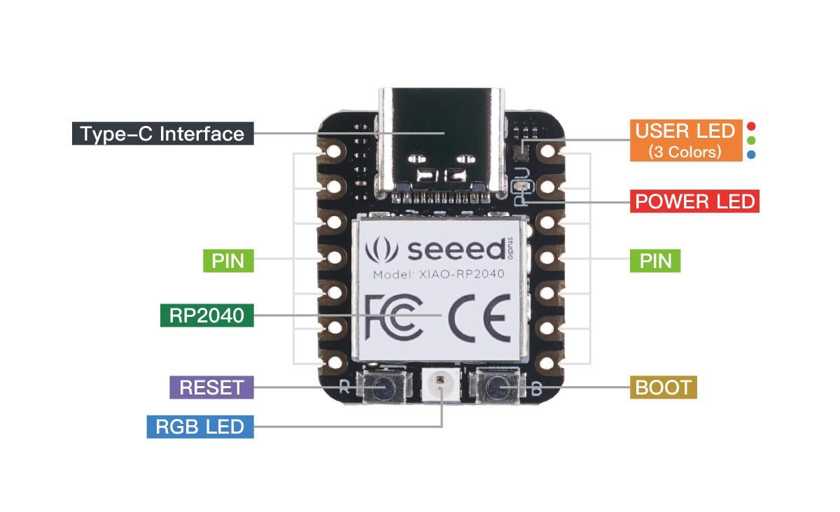

The Seeed Xiao RP2040 is a compact, low-power, and powerful development board based on the RP2040 microcontroller chip developed by Raspberry Pi. The RP2040 is a dual-core Arm Cortex-M0+ processor running at up to 133MHz.
Some key features of the Seeed Xiao RP2040 include:
- Small form factor: The board measures only 20mm x 17.5mm, making it one of the smallest RP2040-based boards available.
- Programmable via USB: The Xiao RP2040 can be programmed directly via USB, without the need for a separate programmer.
- Onboard sensors: The board includes an onboard temperature sensor and a 3-axis accelerometer, allowing it to be used for various sensor-based applications.
- Low power consumption: The RP2040 microcontroller is designed to be energy-efficient, making the Xiao RP2040 suitable for battery-powered projects.
- Extensive I/O: The board provides a range of I/O interfaces, including GPIO pins, PWM, ADC, and I2C/SPI/UART communication.
- Arduino compatibility: The Xiao RP2040 can be programmed using the Arduino IDE, making it accessible to a wide range of users familiar with the Arduino ecosystem.
2. Arduino Introduction
Arduino is an open-source electronics platform based on easy-to-use hardware and software. It is designed to make the process of creating interactive projects more accessible to artists, designers, hobbyists, and anyone interested in creating interactive objects or environments.
The main components of the Arduino ecosystem are:
- Arduino boards: These are the physical microcontroller boards that can be programmed to sense and control various physical world objects. Some popular Arduino board models include the Arduino Uno, Arduino Nano, Arduino Mega, and Arduino Leonardo.
- Arduino IDE: This is the software used to write and upload code to the Arduino boards. The Arduino IDE is based on the Processing programming language and makes it easy for beginners to get started with programming.
- Arduino programming language: The Arduino programming language is based on C/C++ and provides a simplified syntax and easy-to-use libraries for common tasks, such as controlling motors, sensors, and displays.
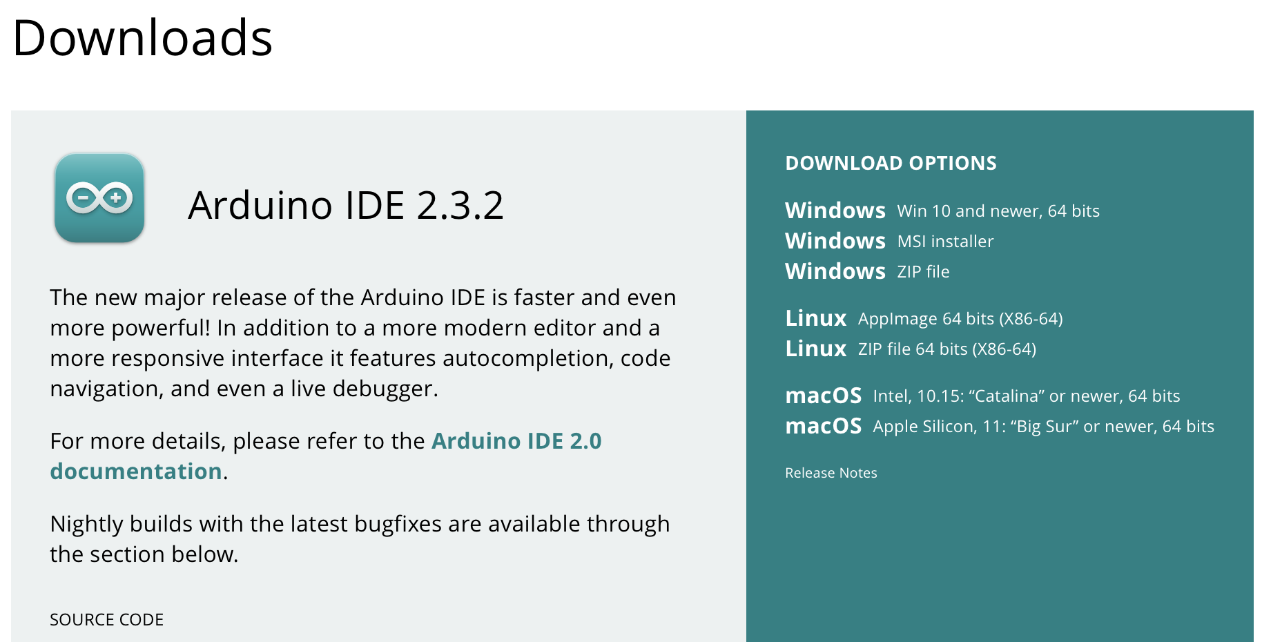
3. Install Arduino IDE
4. Install RP2040 Libary
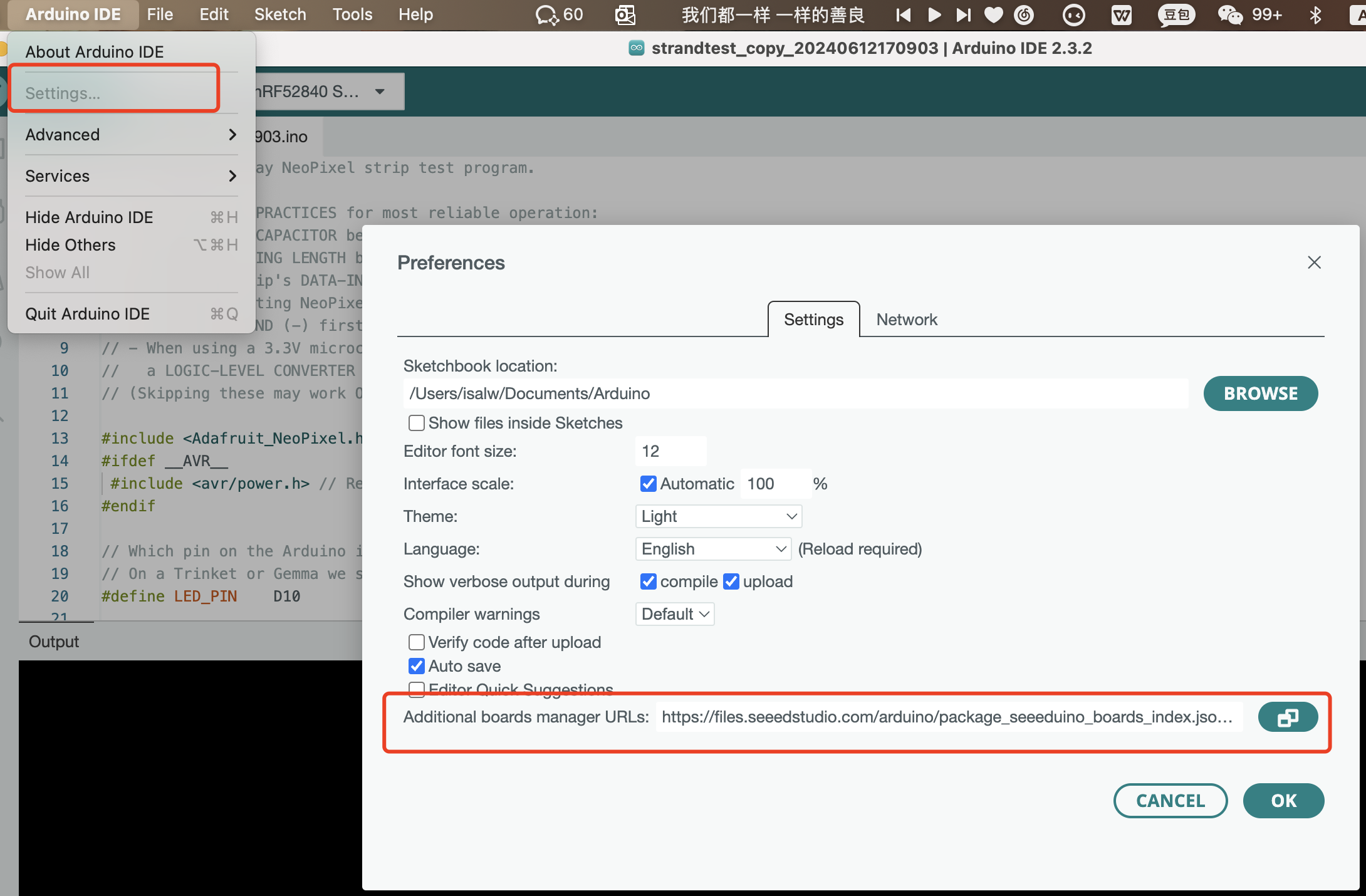
Add Seeed Studio XIAO RP2040 board package to your Arduino IDE
Navigate to Arduino->Settings (if you are using mac), and fill Additional Boards Manager URLs with the url below:
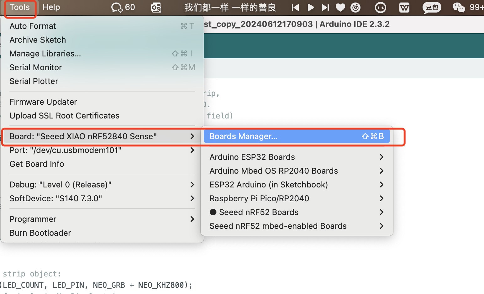
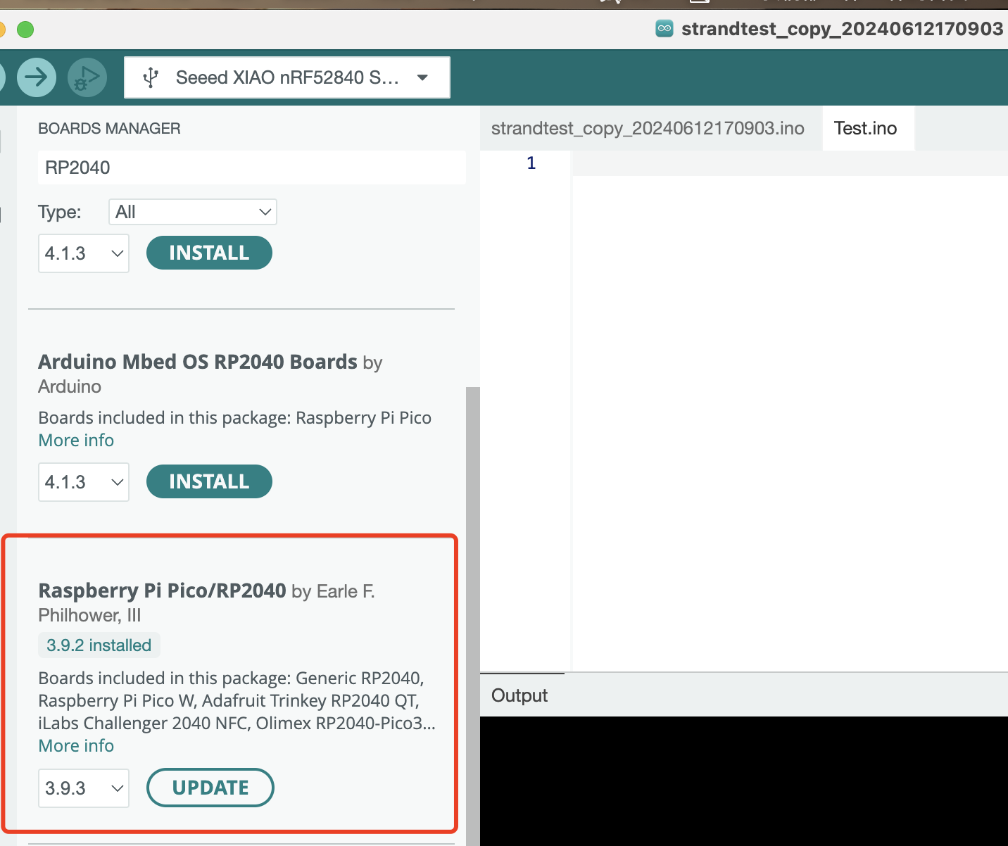
Navigate to Tools-> Board-> Boards Manager..., type the keyword "RP2040" in the searching blank. Select the lastest version of "Raspberry Pi Pico/RP2040" and install it.
Please do not select the mbed OS version, because it may not support the seeed Xiao RP2040.
4. Install RP2040 Libary
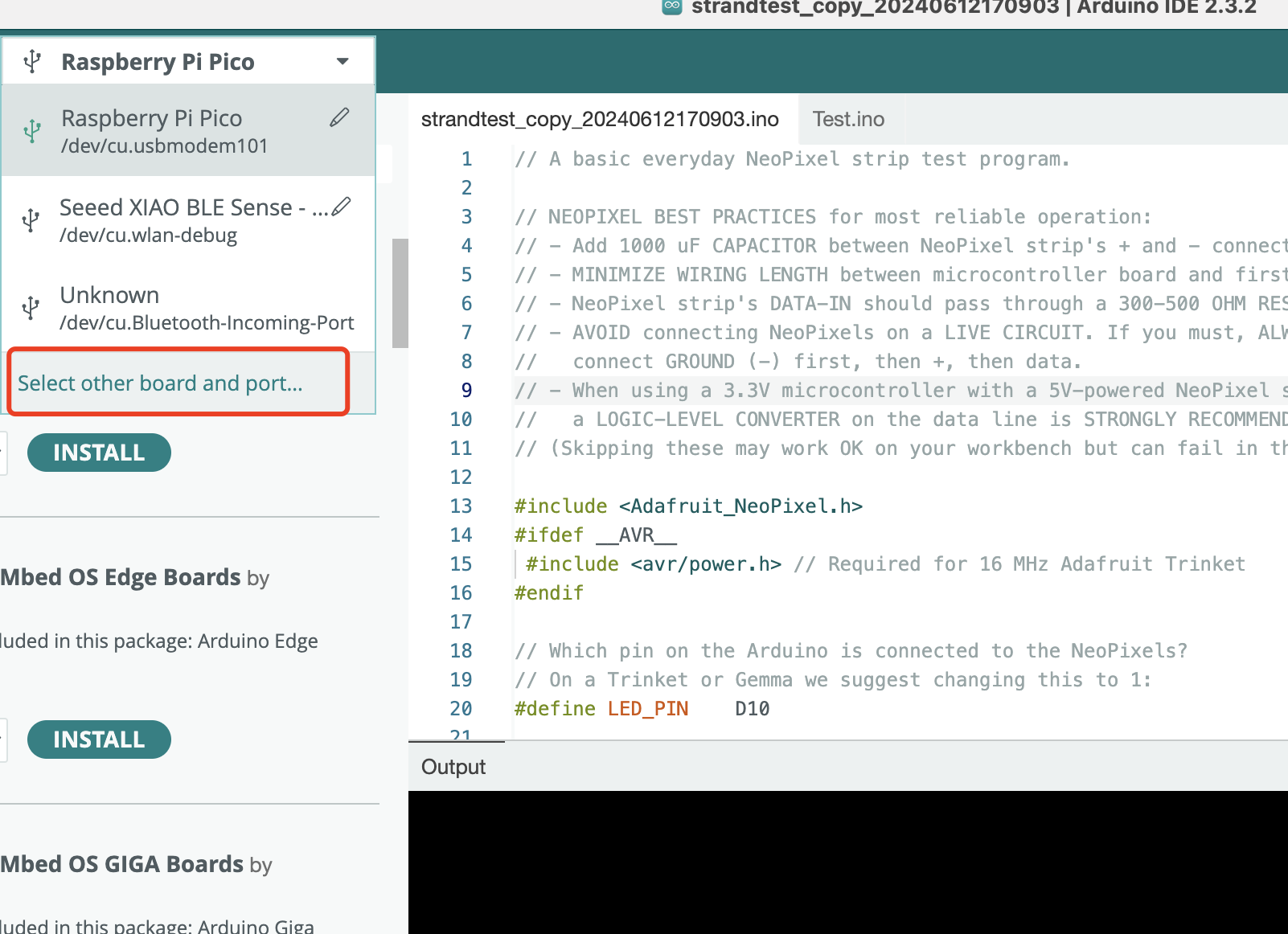
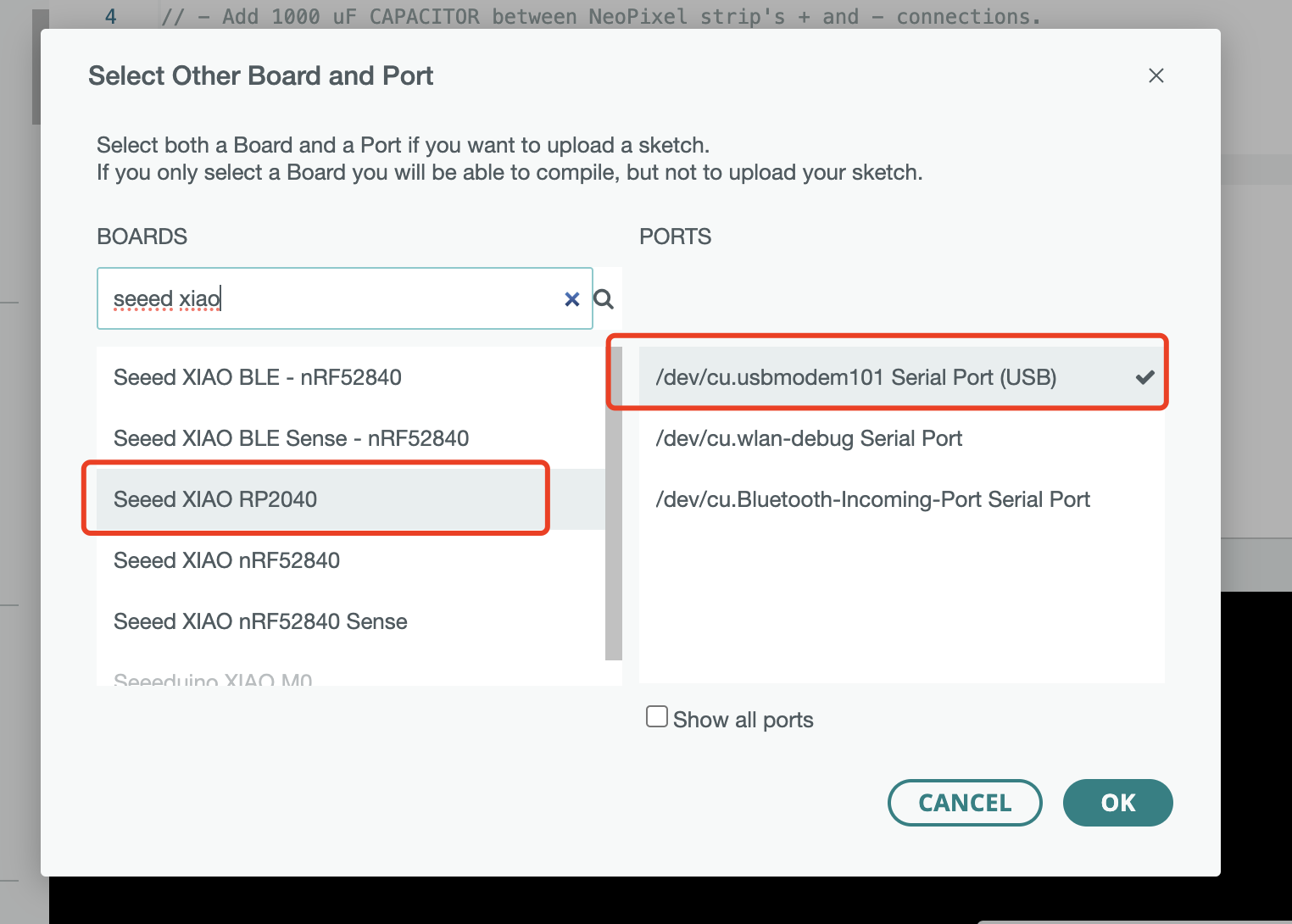
5. Select the Board and Port
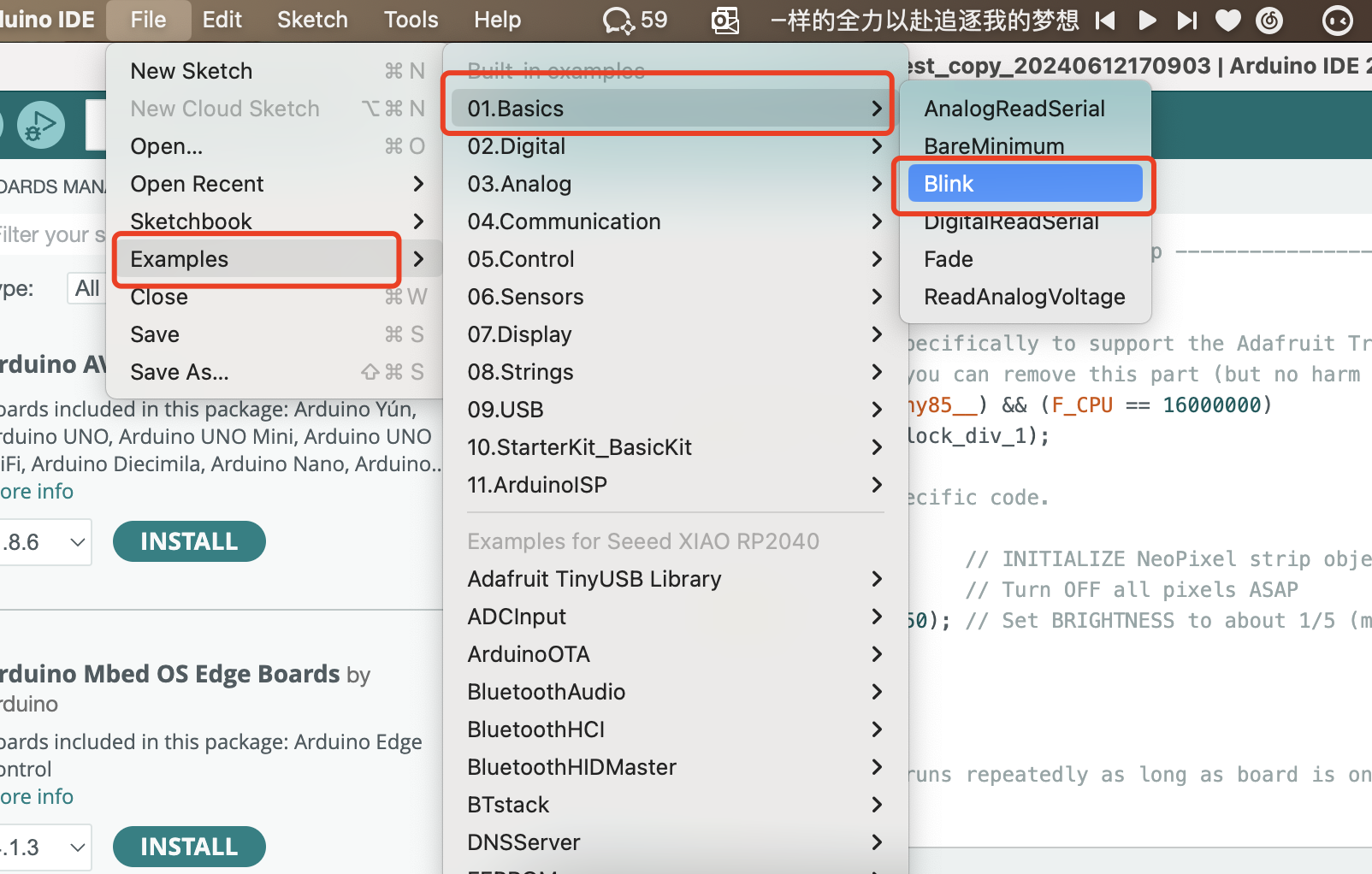
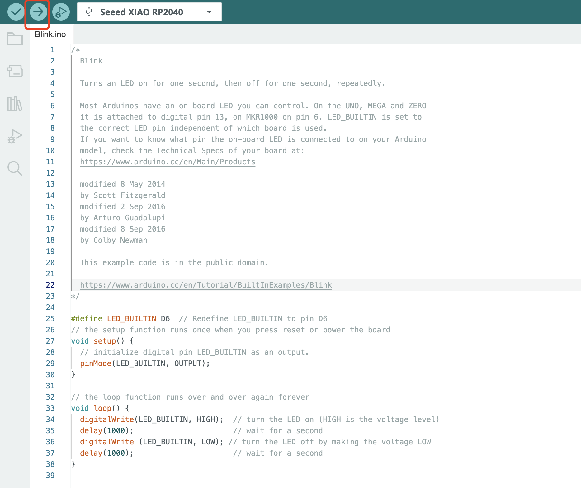
6. Open the Code to Load
Open the Blink example by navigating "File --> Examples --->01.Basics --> Blink
7. Set up the right pin to light up LED
Based on the PCB design of QT, there is a LED connect to the bottom leftmost corner.
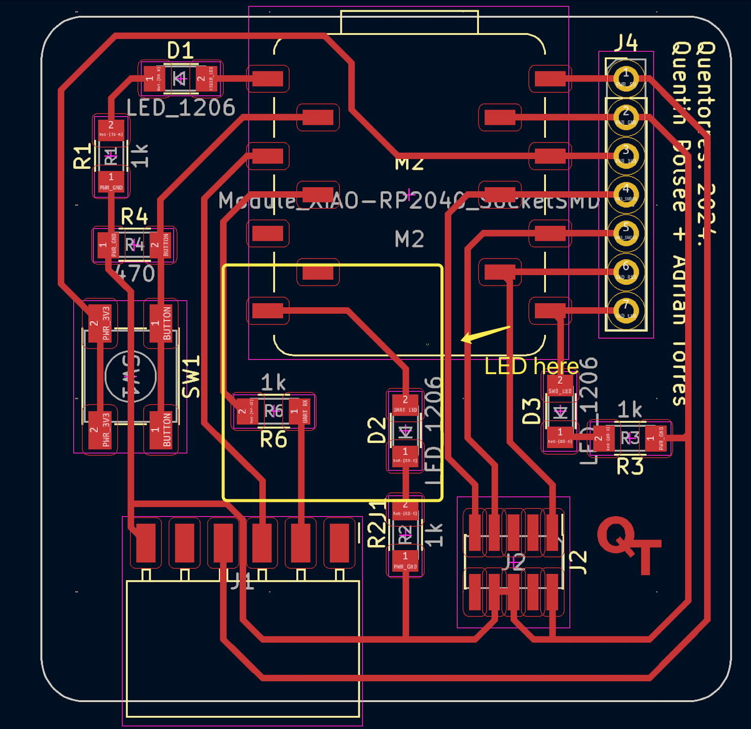
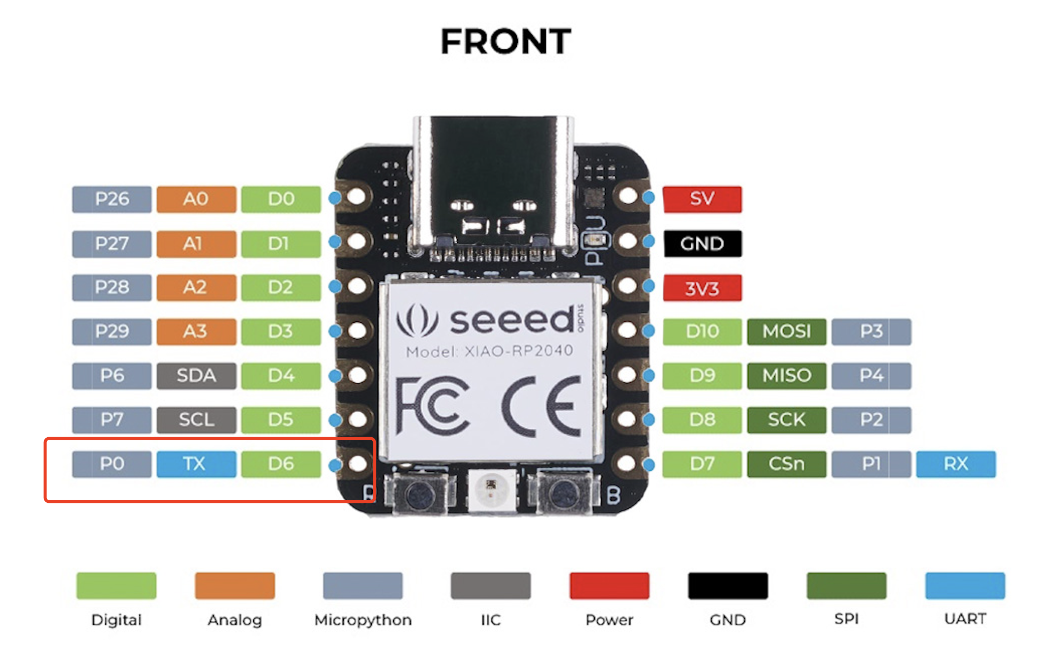
And it corresponds to the D6 on RP2040
So in the code, I added the definition ofLED_BUILTIN to D6
8. The final code
      #define LED_BUILTIN D6  // Redefine LED_BUILTIN to pin D6
     // the setup function runs once when you press reset or power the board
     void setup() {
       // initialize digital pin LED_BUILTIN as an output.
       pinMode(LED_BUILTIN, OUTPUT);
      }

      // the loop function runs over and over again forever
      void loop() {
        digitalWrite(LED_BUILTIN, HIGH);  // turn the LED on (HIGH is the voltage level)
        delay(1000);                      // wait for a second
        digitalWrite (LED_BUILTIN, LOW); // turn the LED off by making the voltage LOW
        delay(1000);                      // wait for a second
     }
9. Explaination of the code
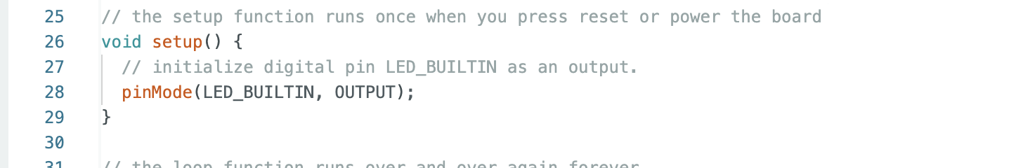
a. Setup Function
In Arduino programming, the setup() function is used for performing one-time initialization tasks that need to be done before the main loop of the program starts.
- It is a special function that is automatically called by the Arduino system when the program begins.
- The main purpose of setup() is to set up the initial conditions and configurations for the program.
- This includes initializing pins (like setting them as input or output), initializing serial communication,
setting up libraries or modules, defining initial values for variables, and performing any other necessary preparations that are required for the proper functioning of the program.
- Once the setup() function is completed, the program enters the main loop and starts executing the code within it repeatedly.
- The specific line pinMode(LED_BUILTIN, OUTPUT); within this function serves the purpose of configuring the digital pin identified as LED_BUILTIN to operate in the output mode.
- By setting it as an output, it enables the Arduino board to actively send electrical signals or voltages through this pin to interact with and control external elements or devices attached to it.
- This initialization step is essential to establish the correct functionality and communication with the connected components, allowing for precise control and manipulation based on the subsequent logic and instructions within the rest of the code.
b. Loop Function
In Arduino programming, the loop() function is a key component.
- It is a continuous block of code that gets executed repeatedly after the setup() function has completed its one-time initialization tasks.
- The main purpose of the loop() function is to contain the main logic and actions that the Arduino sketch should perform continuously throughout the program's runtime.
- This could include reading sensor values, processing data, controlling outputs based on conditions, and communicating with other devices or systems.
- The loop() function keeps running over and over again, allowing the Arduino to constantly monitor and respond to changes in the environment or based on the internal logic of the program.
- It forms the core of the program's ongoing functionality and enables real-time interaction and control.
In this Arduino code snippet, the void loop() function contains the main repetitive logic of the program.
- The line digitalWrite(LED_BUILTIN, HIGH); sets the digital pin LED_BUILTIN to a high voltage level, which turns the LED on.
- Then, delay(1000); introduces a pause of 1000 milliseconds (1 second). This delay ensures that the LED remains on for one second.
- After the delay, digitalWrite(LED_BUILTIN, LOW); sets the pin to a low voltage level, effectively turning the LED off.
- Again, delay(1000); causes a one-second pause to keep the LED off for one second.
- This sequence of turning the LED on for one second and then off for one second repeats continuously as long as the Arduino is powered and the program is running.
- The loop() function ensures that this cycle of LED toggling occurs repeatedly, creating a blinking effect.
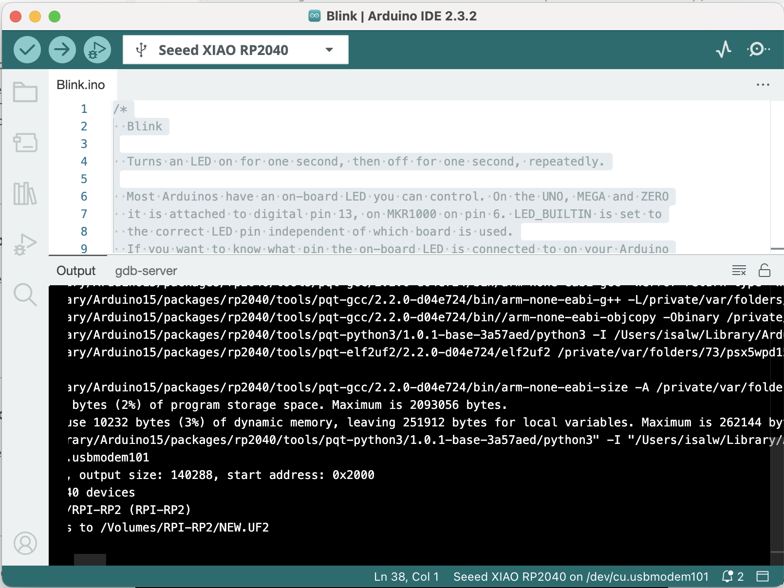
10. Upload the Code to RP2040
All Code Finished Uploading
11. Blink