Week5 Group Assignment 3D Printing
The Group Assigement for week5 is to test the design rules for the 3D printers we are using
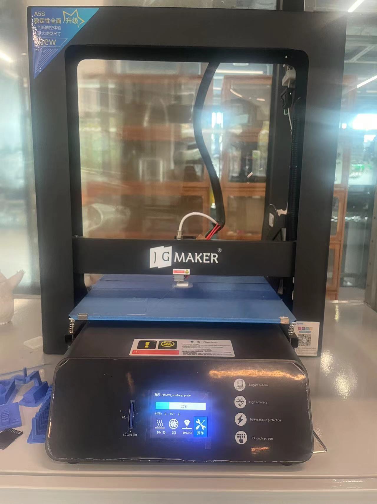
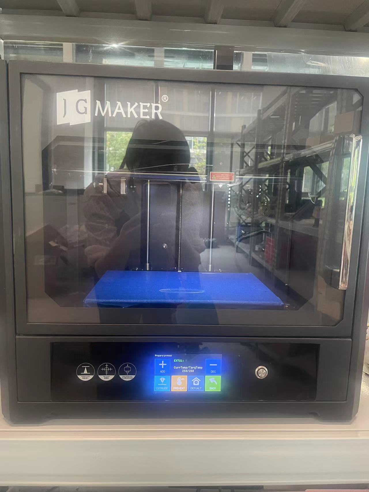
The 3D printers in ISALW are currently JGAurora-5s and JGAurora-6. The material we used for printing is PLA. To expedite the process, we utilized both machines to conduct the test.
Testing Started
All the stl files could be downloaded directly from the FAB Academy websites. Students from prior cohorts had already manufactured similar sets to examine unsupported angles, overhangs, and bridges. An extra assessment entailed a set specifically for additional bridges.
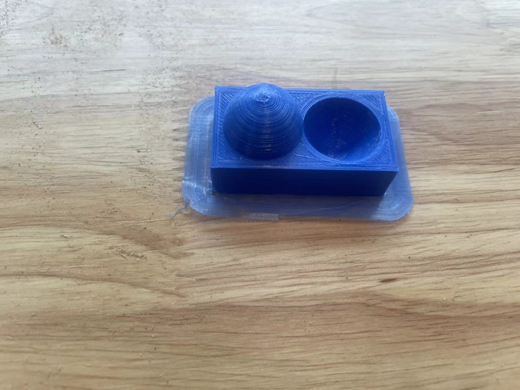
01 Supported Overhang
This overhang with support is clearly very stable and doesn't have any angle differences.
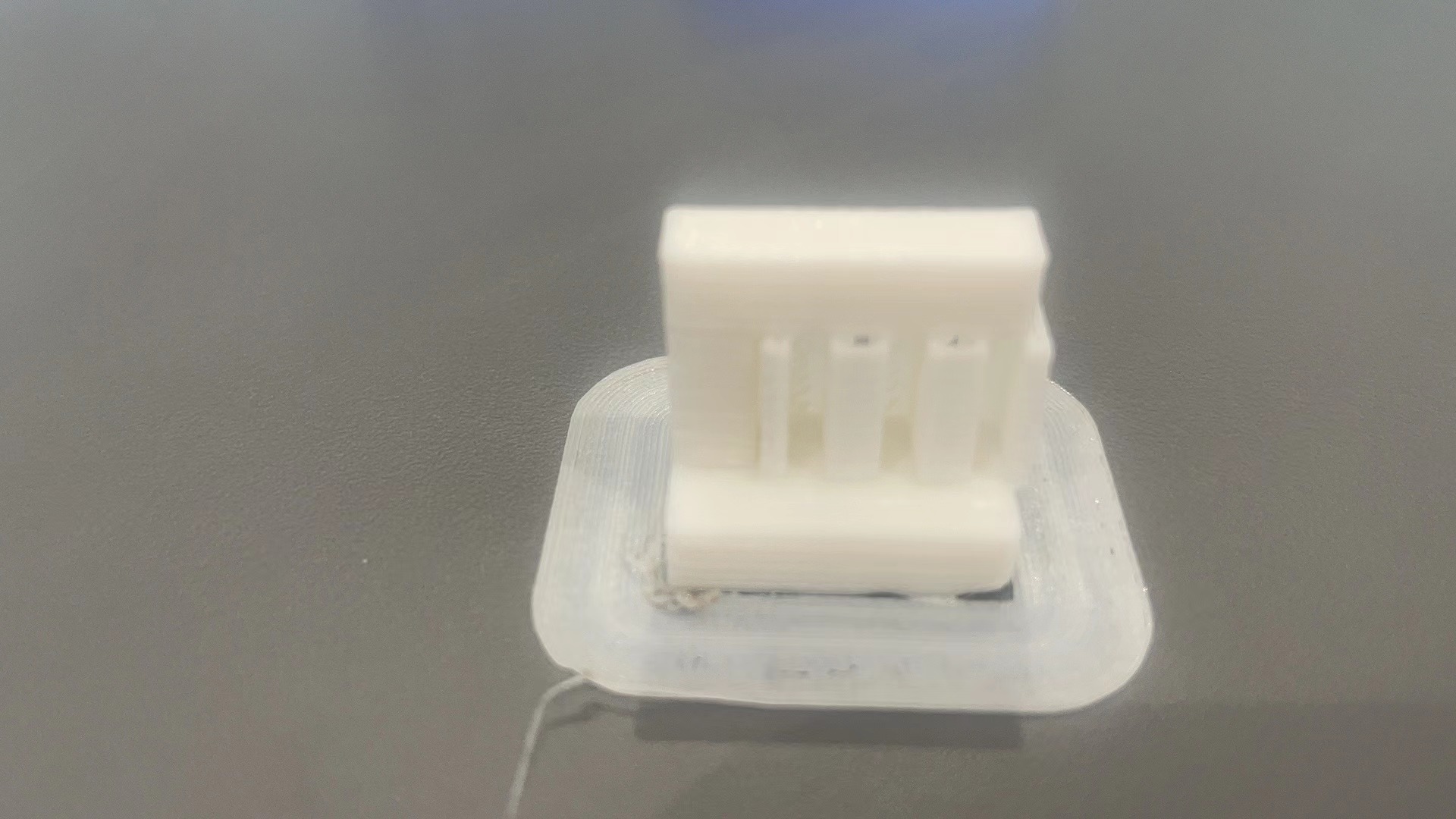
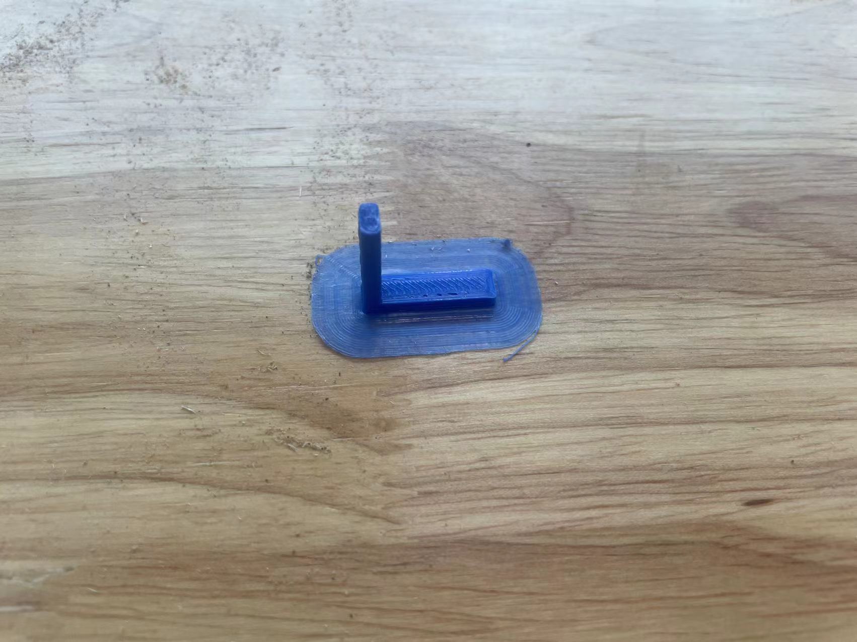
02 Supported Clearance
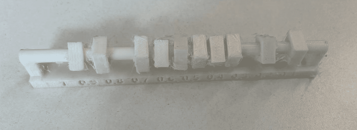
This gauge tests our 3D Printers ability to resolve small clearances between parts. It is a valuable tool for determining what you need to use in your designs to create moving parts without them fusing together.And it was a success to clear it.
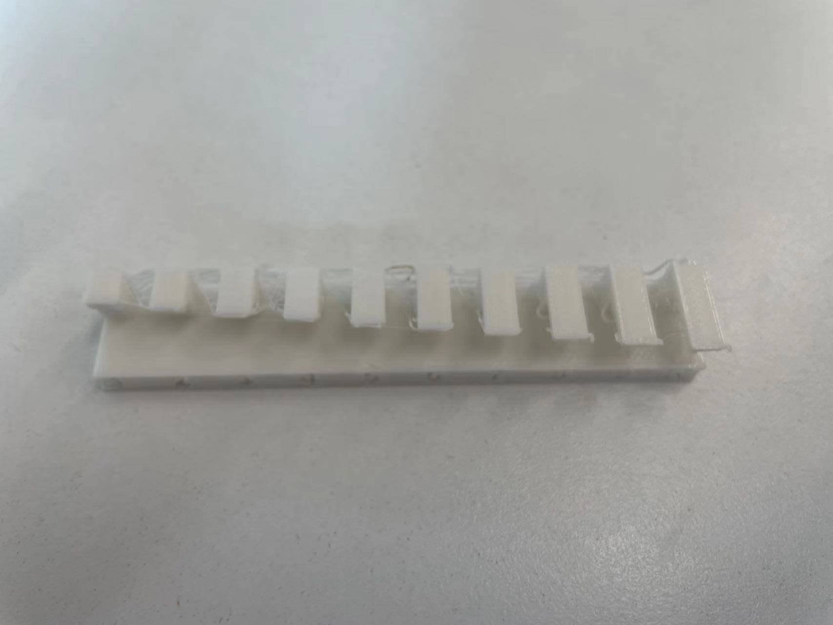
03 Unsupported Angle

At 45 degrees, every layer is in about 50% contact with the layer below it and hence prints well. Slope angles greater than 45-degrees, are generally chambered to print without supports.
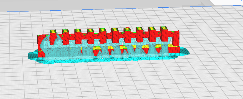
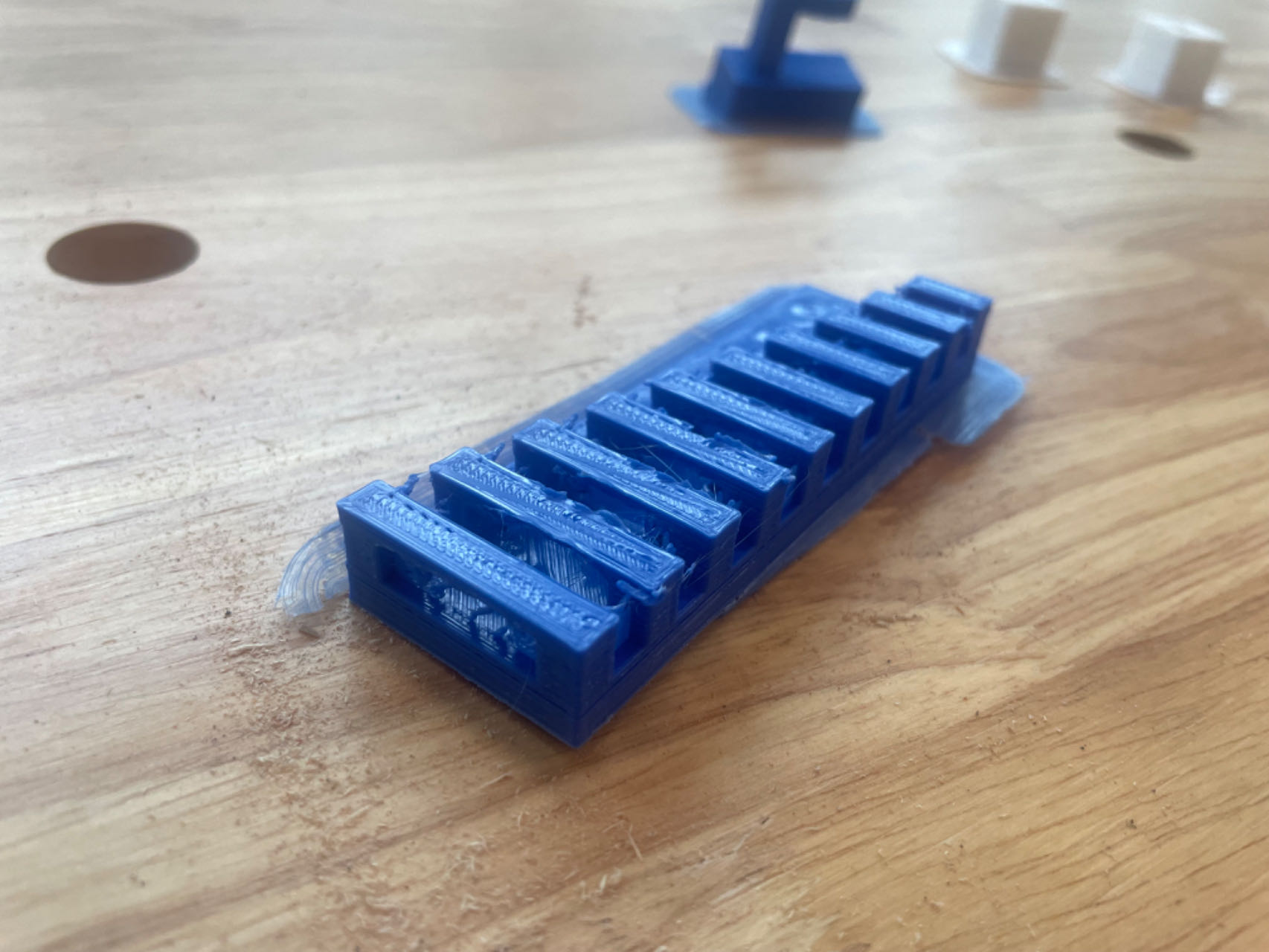
04 Unsupported Overhang
When printing unsupported overhangs we need the filament to cool down as soon as possible to prevent the filament from falling due to gravity. Increase the speed of the layer fan, in this way the filament will solidify faster and will serve as support for the rest of the layers.
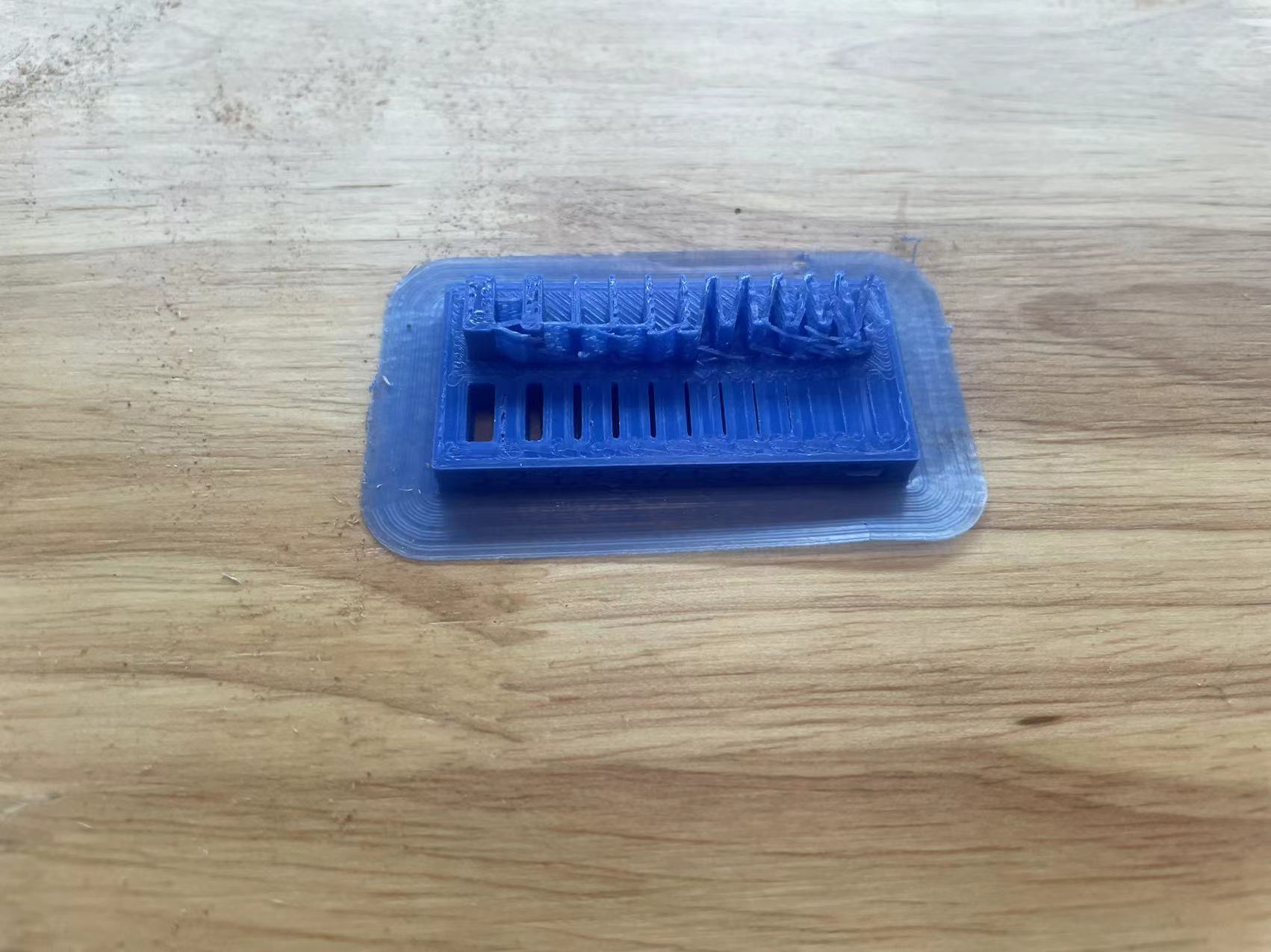
05 Unsupported Bridging
Extrusions over air without anything below it will look stringy, this is because there is nothing below it for the filament to get squished against. More support may make it less stringy but then you may have another problem of getting rid of the supports too.
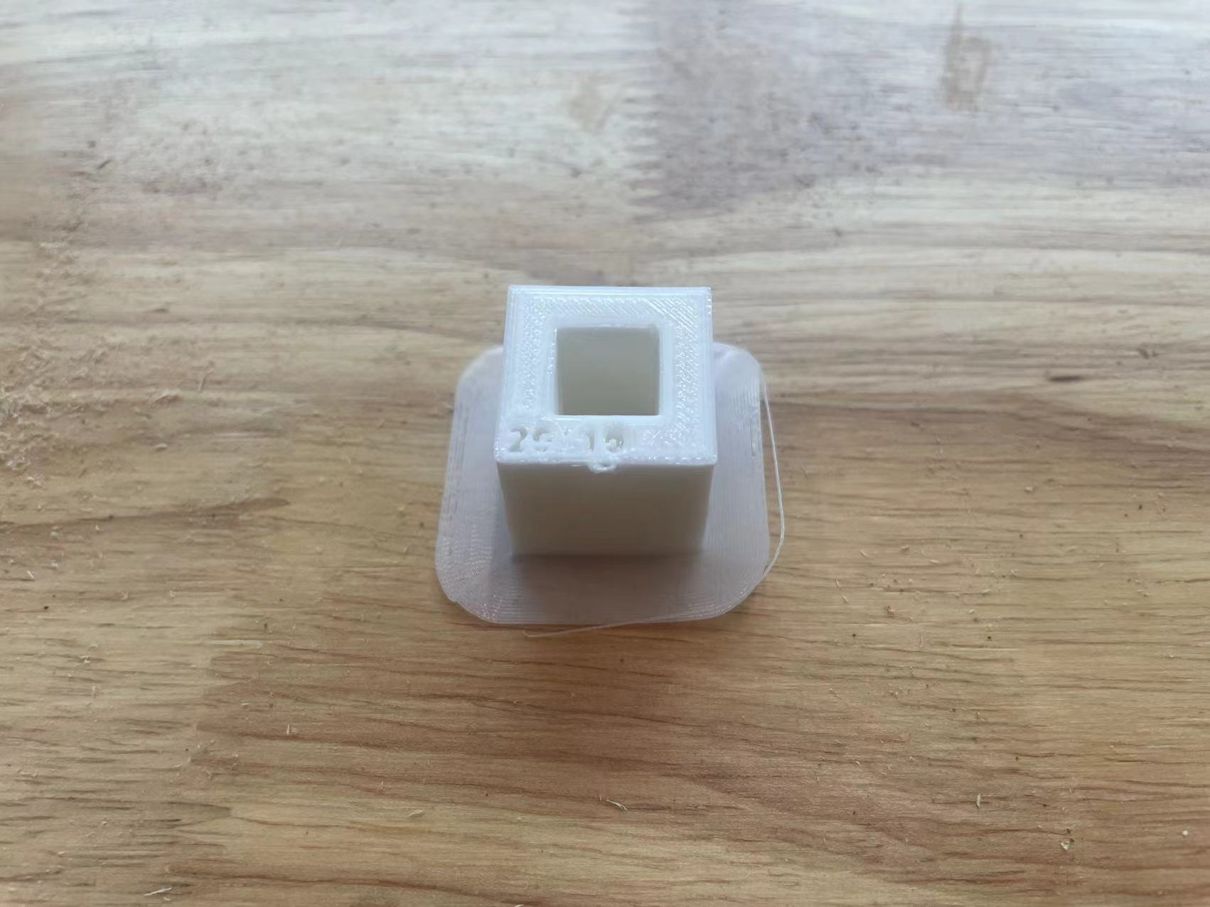
06 Wall Thicknesss
Our first product with a wall thickness was a disaster because the materials were too close together, making it difficult to distinguish the walls clearly.
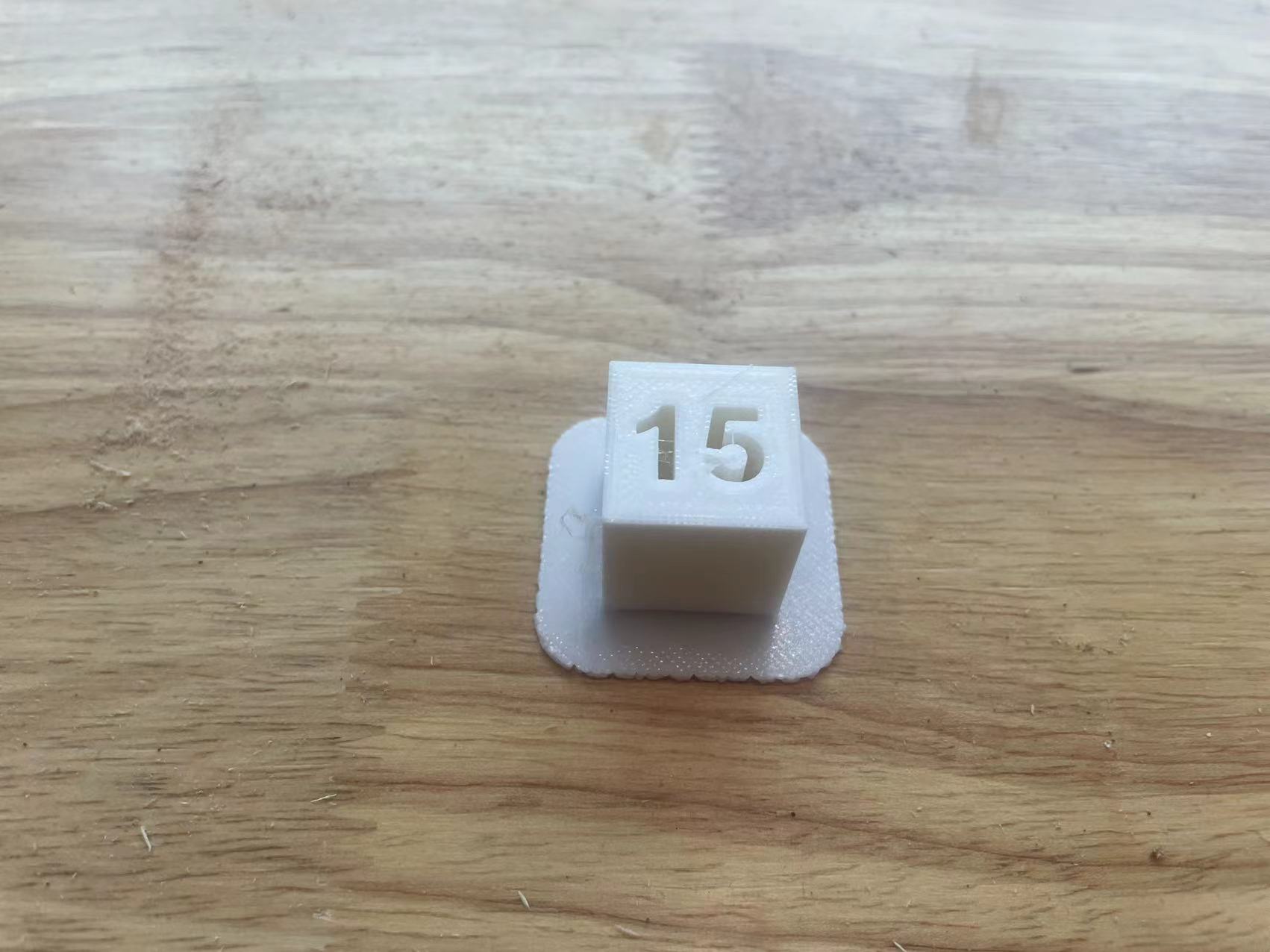
07 Dimensions
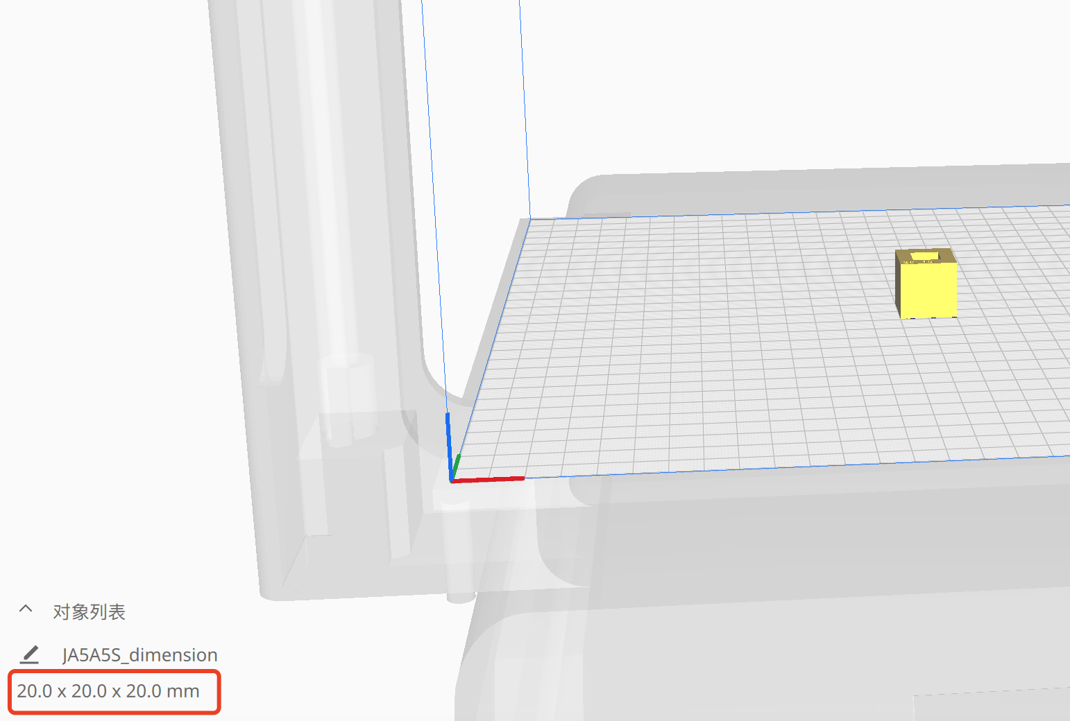
The dimensions of the 3D printed object match the slicing parameters, both of which use millimeters.
08 Anistrophy
The anisotropy of 3D printing concrete will weaken the concrete structure's integrity and mechanical bearing capacity. Therefore, many researchers have studied the mechanical anisotropy of 3D printing
09 Surface
The surface quality of 3D printed parts varies depending on the 3D printing technology used, the quality of the printer, and the material being used. The design of the part, as well as its position and orientation during printing, also impact the surface quality. While the surface of PLA objects appears acceptable, further processing is required to achieve a smoother finish.
10 Infill
“Infill” in 3D printing refers to the internal patterns found inside most 3D printed parts. Parts made by some manufacturing processes, like injection molding, must be made either completely solid or completely hollow. 3D printed parts, on the other hand, can be made with a variety of structural patterns that partially fill the space inside the outer printed walls. Almost all 3D printing technologies require infill. This is the case because printing objects in a solid material are too costly and time-consuming.