Week 11 - Group assignment
The goal of this assignment is to probe the analog / digital signals from a sensor.
I used an oscilloscope to probe the analog signals in real time of a flex sensor (used later in week 14 interfaces).
The circuit to use the flex sensor is pretty simple, you only need to make a voltage divider bridge with a 47kOhms resistor, as in the following schematic found on Sparkfun which gives more details about the use of this fun sensor.
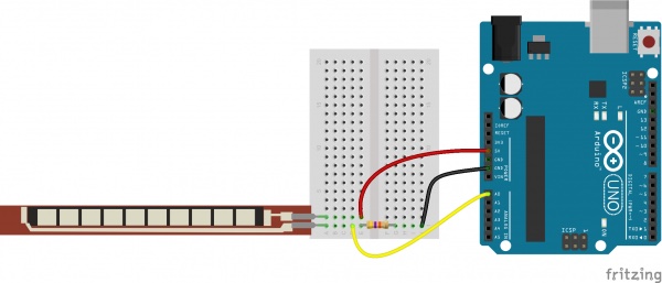
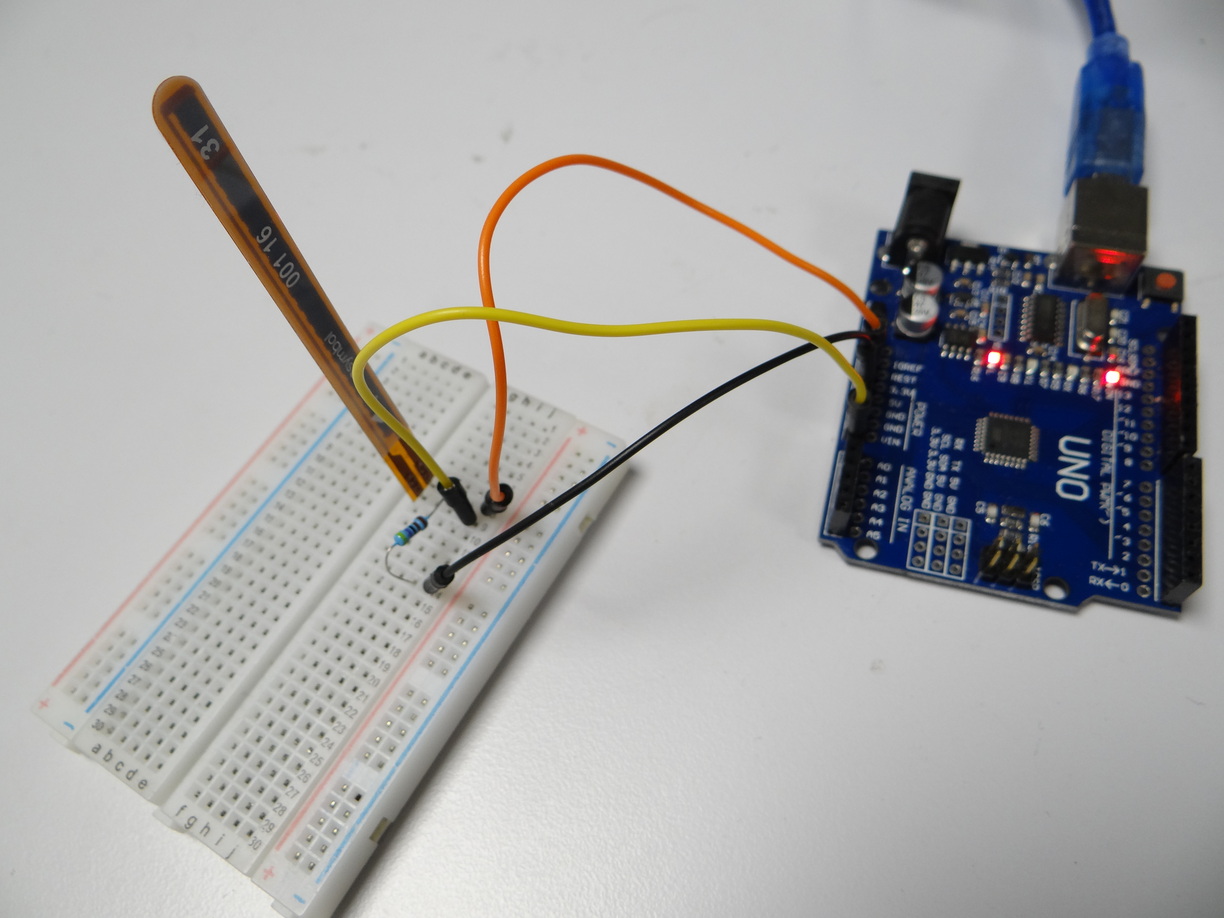
I connected the sensor to the arduino pin A0 and uploaded the following code to the board, also provided by Sparkfun:
/******************************************************************************
Flex_Sensor_Example.ino
Example sketch for SparkFun's flex sensors
  (https://www.sparkfun.com/products/10264)
Jim Lindblom @ SparkFun Electronics
April 28, 2016

Create a voltage divider circuit combining a flex sensor with a 47k resistor.
- The resistor should connect from A0 to GND.
- The flex sensor should connect from A0 to 3.3V
As the resistance of the flex sensor increases (meaning it's being bent), the
voltage at A0 should decrease.

Development environment specifics:
Arduino 1.6.7
******************************************************************************/
const int FLEX_PIN = A0; // Pin connected to voltage divider output //AO on arduino UNO, PB4 = GPIO6 = 5 on my attiny3216 devboard

// Measure the voltage at 5V and the actual resistance of your
// 47k resistor, and enter them below:
const float VCC = 4.98; // Measured voltage of Ardunio 5V line
const float R_DIV = 47500.0; // Measured resistance of 3.3k resistor

// Upload the code, then try to adjust these values to more
// accurately calculate bend degree.
const float STRAIGHT_RESISTANCE = 20747; // resistance when straight //37300 //20747
const float BEND_RESISTANCE = 36280.0; // resistance at 90 deg //36280

void setup()
{
  Serial.begin(9600);
  pinMode(FLEX_PIN, INPUT);
}

void loop()
{
  // Read the ADC, and calculate voltage and resistance from it
  int flexADC = analogRead(FLEX_PIN);
  float flexV = flexADC * VCC / 1023.0;
  float flexR = R_DIV * (VCC / flexV - 1.0);

  // Use the calculated resistance to estimate the sensor's bend angle:
  float angle = map(flexR, STRAIGHT_RESISTANCE, BEND_RESISTANCE,
                   0, 90.0);

  Serial.println(angle);
  delay(100);
}
Then I connected two jumpers to the pin A0 and to the ground and probe it on the channel 1 of the oscilloscope.
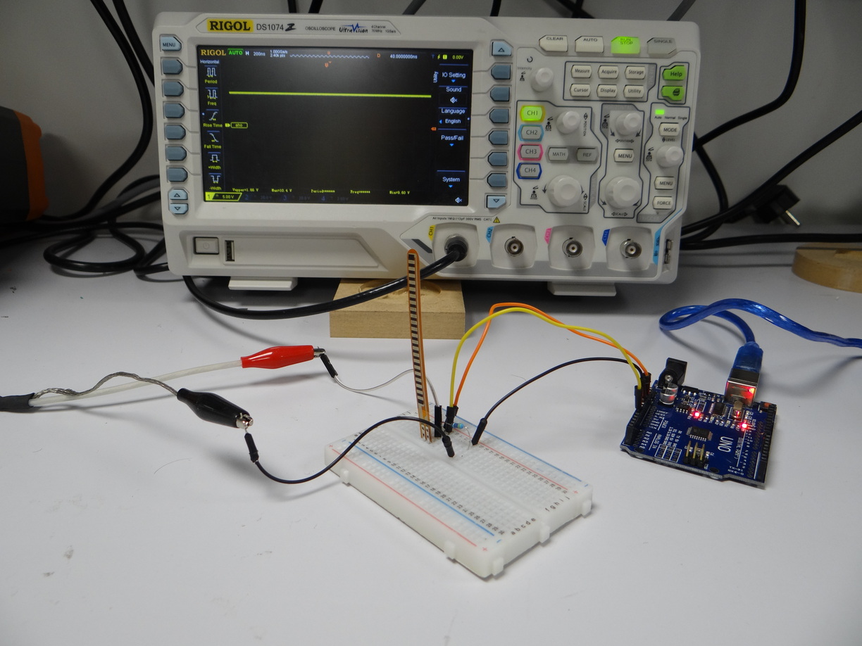
I adjusted the voltage reading level to observe the variations in the voltage as I bended the flex sensor, and the horizontal unit (duration per division) to plot them nicely in real time.
With 5V per division in vertical and 500ms per division in horizontal, we can observe the voltage variations.
The screen gives us the voltage variations, as well as extremes voltage measures:
- Max 10.2 V when the flex sensor is standing freely with no flexure apply to it
- Min 2.0 V when the flex senssor is strongly bent
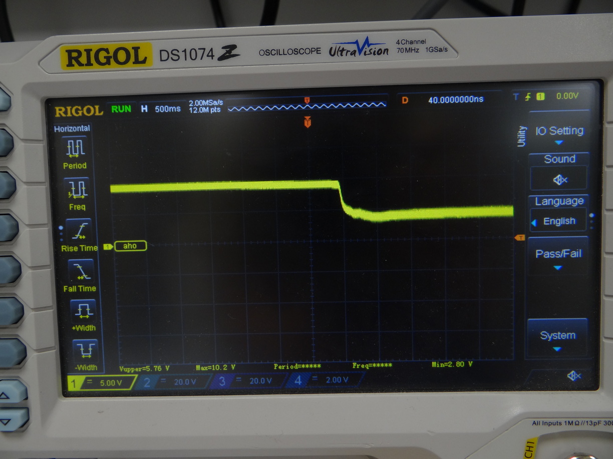
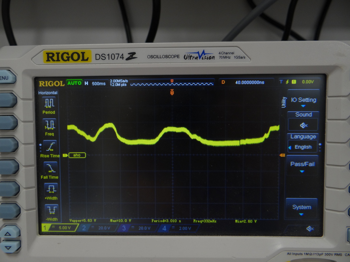
Apparently the oscilloscope tries to calculate a period and the corresponding frequency, even if it's a non periodic signal