Week 11 - Input devices
Goals
- individual assignment: measure something: add a sensor to a microcontroller board that you have designed and read it
- group assignment: probe an input device's analog levels and digital signals
Week's explorations and achievments
I oriented this week's work towards accelerometers.
- I first picked the SMD tiny component ADXL 343 that we had in the lab.
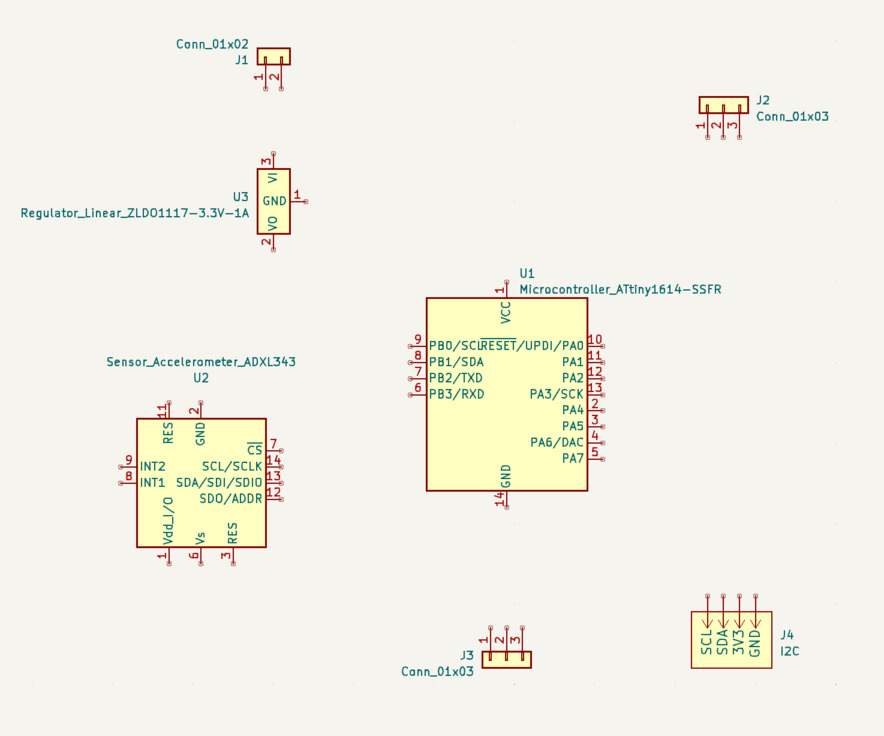
- I draw the general design of a new board with an ATtiny1614 and chose the components and features: the ADXL 343 working with I2C, an I2C grove connector and headers for a led strip
- I designed it in KiCad
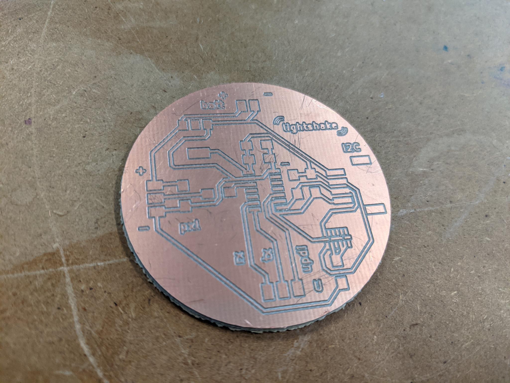
- I milled it
- I soldered the components, and discovered how to use solder paste with a paper mask
- I programmed it via UPDI
- I could achieve serial communication
- I downloaded the Adafruit libraries
- I couldn't make the ADXL 343 to work
- Browsing through some other students documentation I realised I missed something in the datasheet
- I went back to the datasheet to use ADXL 343 with I2C
- I made a small adjustment on my board (connect the ADXL 343 pins CS and VDD and elongate its pads)
- I milled it, soldered it, programmed it
- The ADXL 343 wasn't recognised by the programm
I2C-scanner:,(
- I moved forward with a simpler component to use, the Adafruit breakout board with a MMA8458.
- I connected it to my I2C grove on my second board
- I downloaded the Adafruit library
- I uploaded the demo example which worked
- I observed in the serial port the evolution of the x, y and z informations while moving the accelerometer
- I adapted the example code to better understand how to manipulate the library's parameters
- I first use the orientation predefined cases to light up the led strip with different colors
- I then tried to detect variations illustrating a shaking movement. I started with w and introduced two measures of x delayed by a few milliseconds, in order to trigger specific actions if this difference is above a certain level
- I detected the important variations on x, y and z axis which triggered the strip lighting in various colors (red for x, green for y, blue for z)
- I modified the code to control the led colors as I intend to do in my final project
- I played around with the formulas to obtain a color gradient between the two colors at each tip of the strip
- It worked 8-)
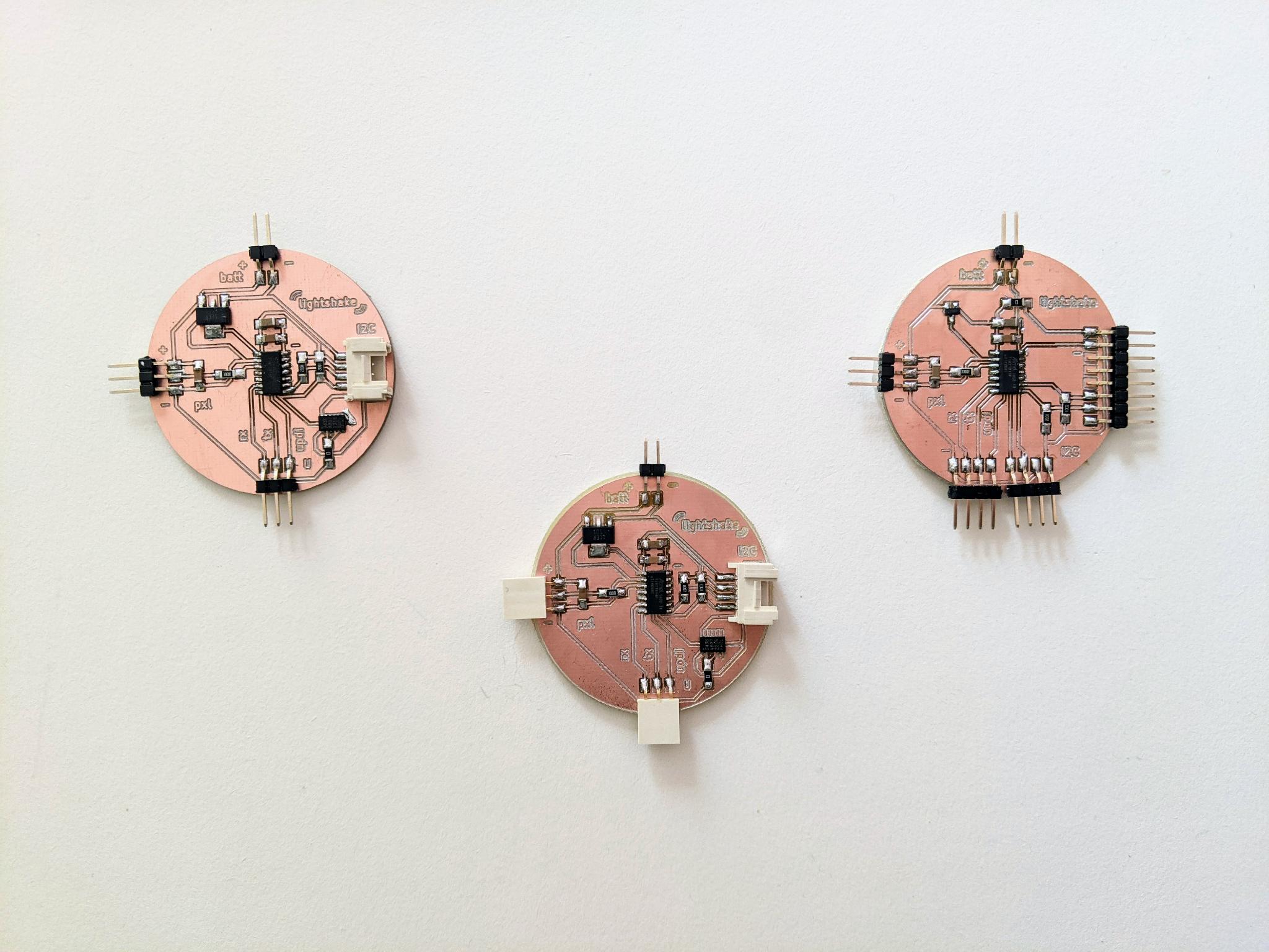
- I ultimately modified my design and produced a third board without an ADXL343
We unfortunately didn't have the time for the group assignment :(
An idea using an accelerometer for my palette palet:
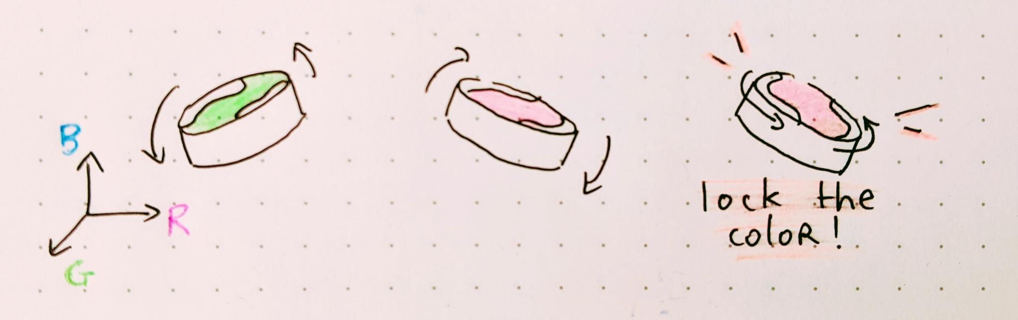
The idea I've partly demonstrated this week with an accelerometer:
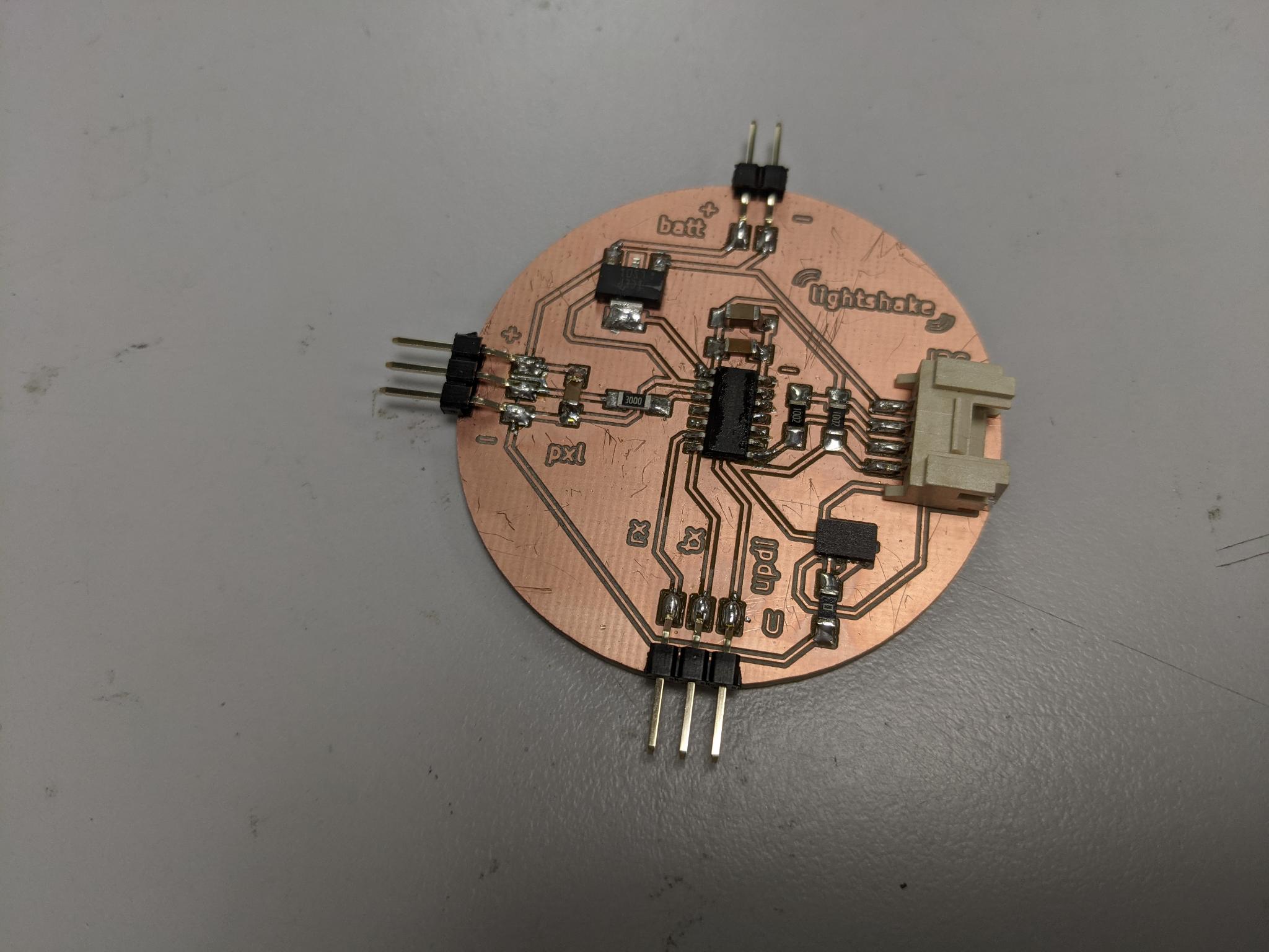
Three boards made this week:
Group assignment
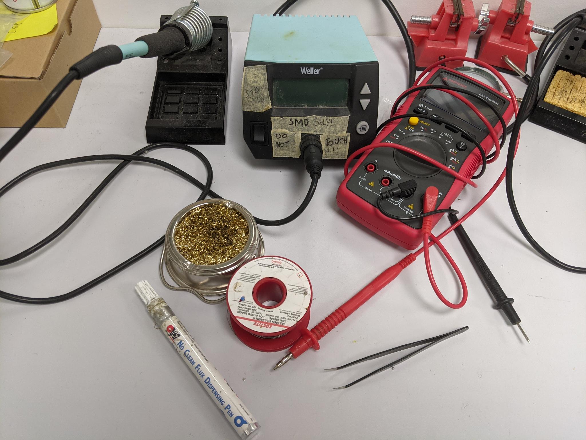
The goal of the group assignment was to probe signals from an input device. I used a flex sensor and observed the voltage evolution through an oscilloscope.
New lightshake I2C board
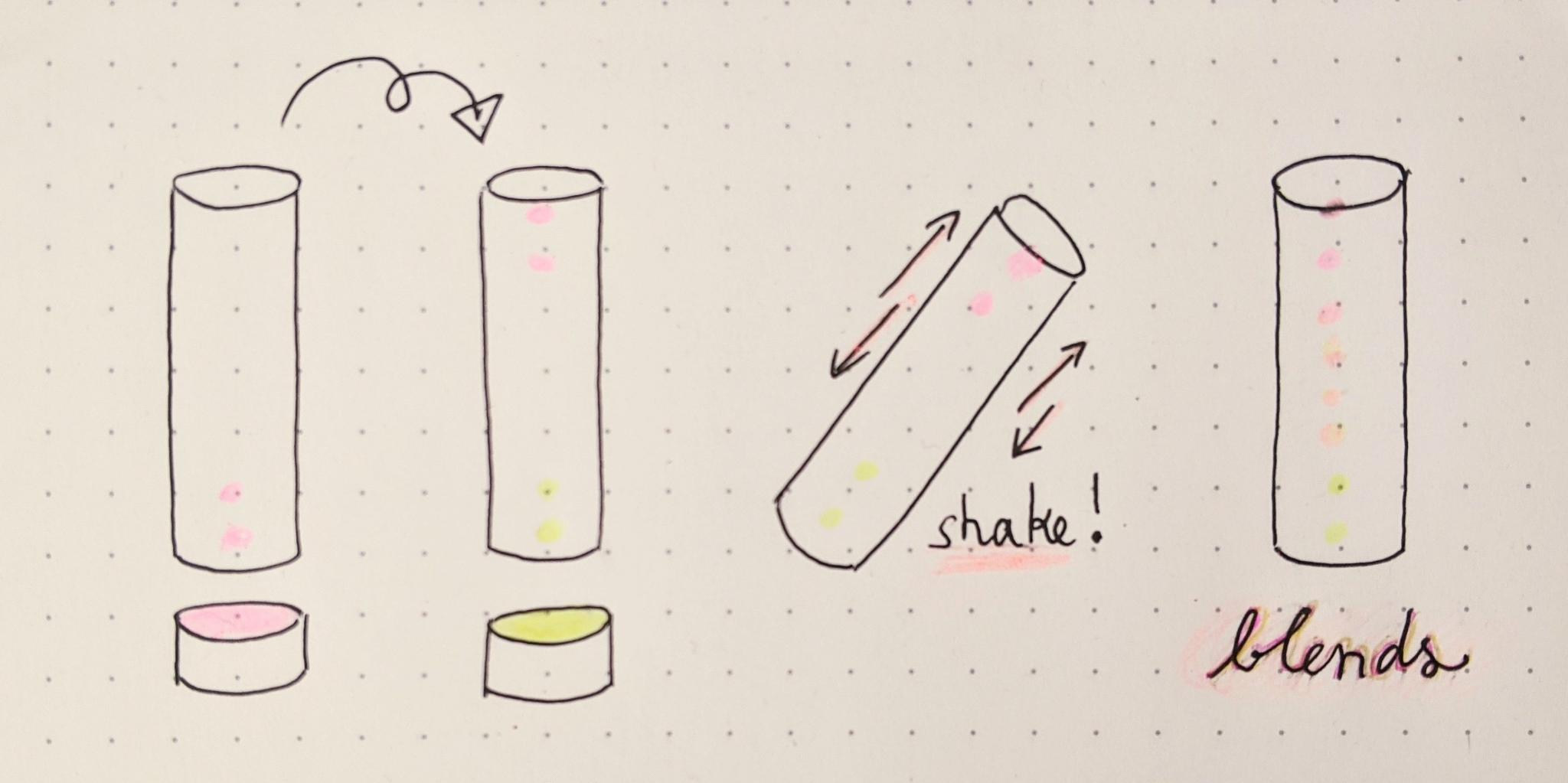
The final goal for this board is to be integrated into a light tube. The tube can be 'filled' with different colors at each tip of the led strip. When shaken, the colors must blend.
The board works thanks to an ATtiny1614. It can thus be programmed through UPDI with the help of an external UPDI board programmer. It can communicate with the serial monitor thanks to the FTDI provided by the same external programmer. It is powered either by USB if connected to the programmer, or with a 3.7V Lipo battery. It provides header pins to connect a LED strip It provides an I2C grove connector for further communication with another circuit.
Components
| Components name | Description, use | Value / Specs | Package informations | Datasheet or vendor link |
|---|---|---|---|---|
| ATtiny1614 | Microcontroller | SOIC14 | datasheet | |
| 2 capacitors | Filter the signal for the microcontroller | 1uF and 100nF | 1206 | |
| ADXL343 | 3 axis accelerometer | SOIC14 | datasheet | |
| ZLDO1117 1A 3.3V | Voltage regulator | SOT 223 3 | ||
| 2 pullup resistors | On SCL and SCL lines | 10kOhm | 1206 | |
| 1 capacitor | Filters the signal for the led strip | 470nF | 1206 | |
| 1 resistor | to protect the led strip | 300 Ohms | 1206 | |
| BH2103220019- 90 D grove | grove connector for I2C communication | 300 Ohms | 1206 | |
| 3 pins header horizontal | for the UPDI / FTDI communication | 1x03 | 2.54mm | |
| 3 pins header horizontal | fto connect the led strip | 1x03 | 2.54mm | |
| 2 pins header horizontal | to plug the LiPo battery | 1x02 | 2.54mm |
External components :
- RGB WS2812B leds strip
- 3.7V LiPo Battery
- UPDI / FTDI porogrammer board (only to programm and test)
- USB male-female cable (only to programm and test)
Design
I started with a paper sketch.
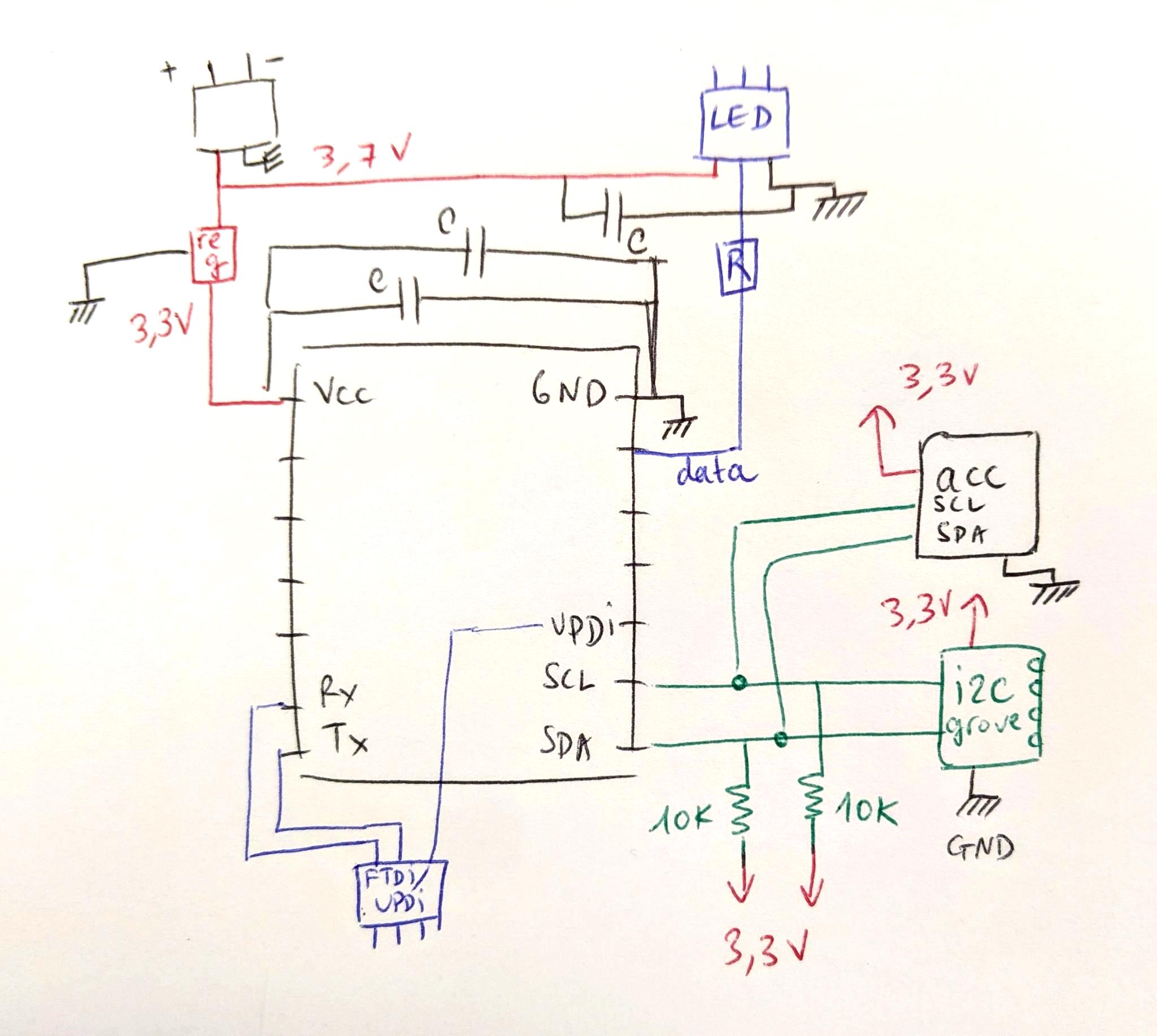
I thus transposed it in KiCad. I already had all the symbol (the ADXL343 is in the fab library) except the grove connector that my instructor send me. I put it in my repository alobng with the kicad files.
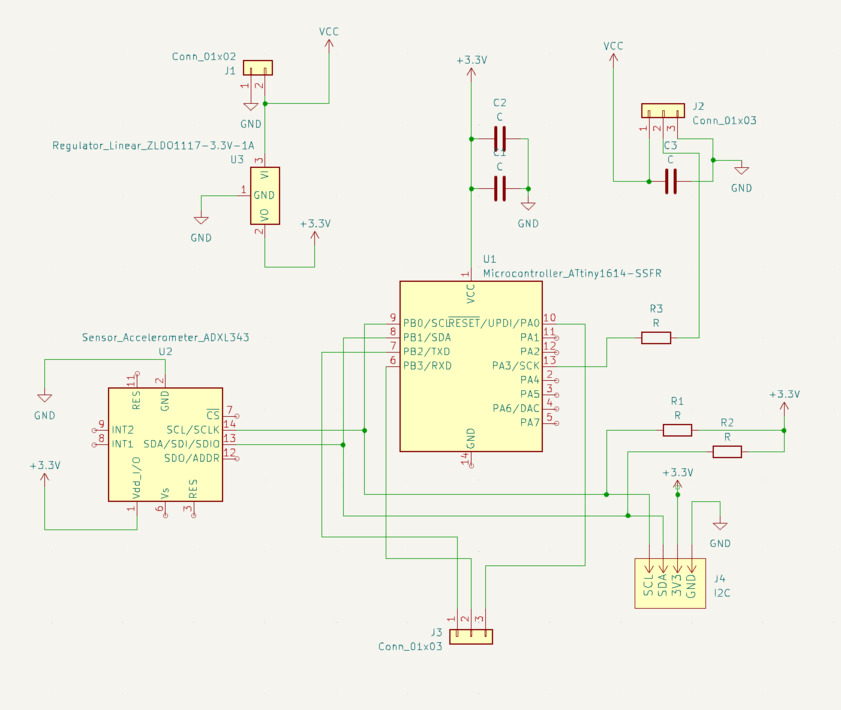
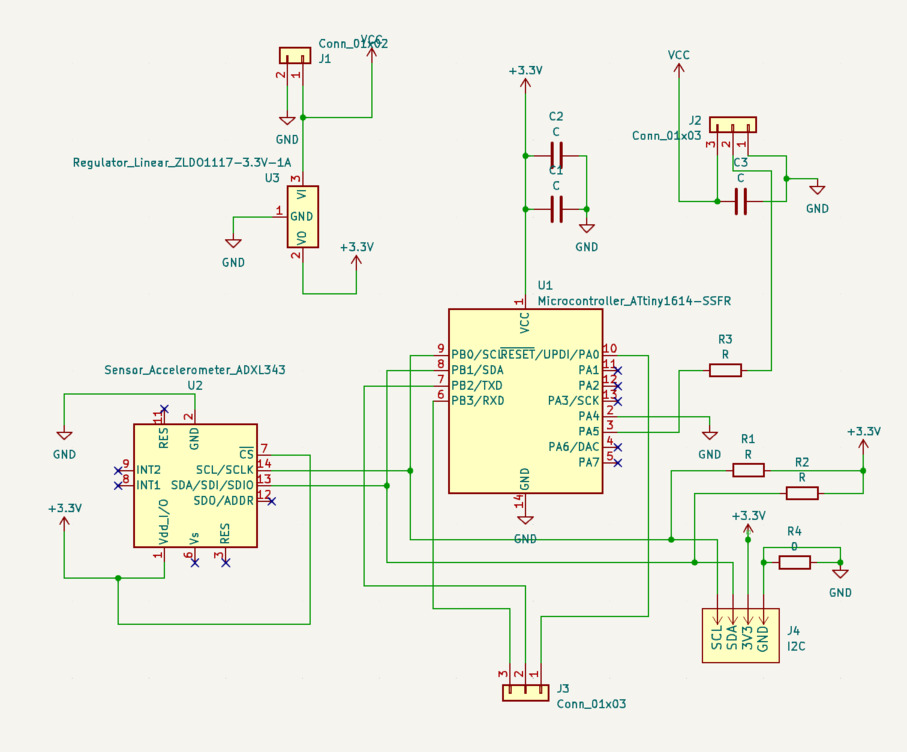
I ran the electricam rules checker which gave me two pieces of information:
- Missing connections. I thus indicated which line shouldn't be connected (see next screenshot)
- Missing power input. This is normal because my battery is external and not indicated on the schematic. But maybe there's a cleaner way to indicate it.
Routing
Routing was okay but a bit long as usual, and I had to use a zero ohm resistor.
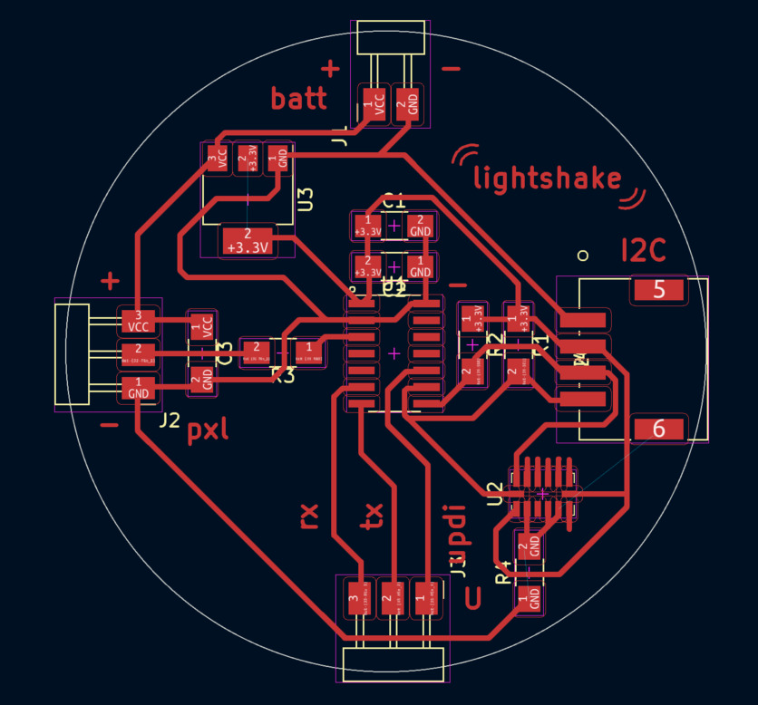
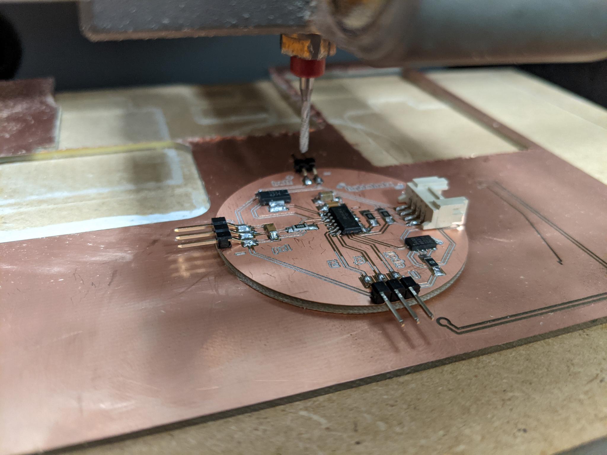
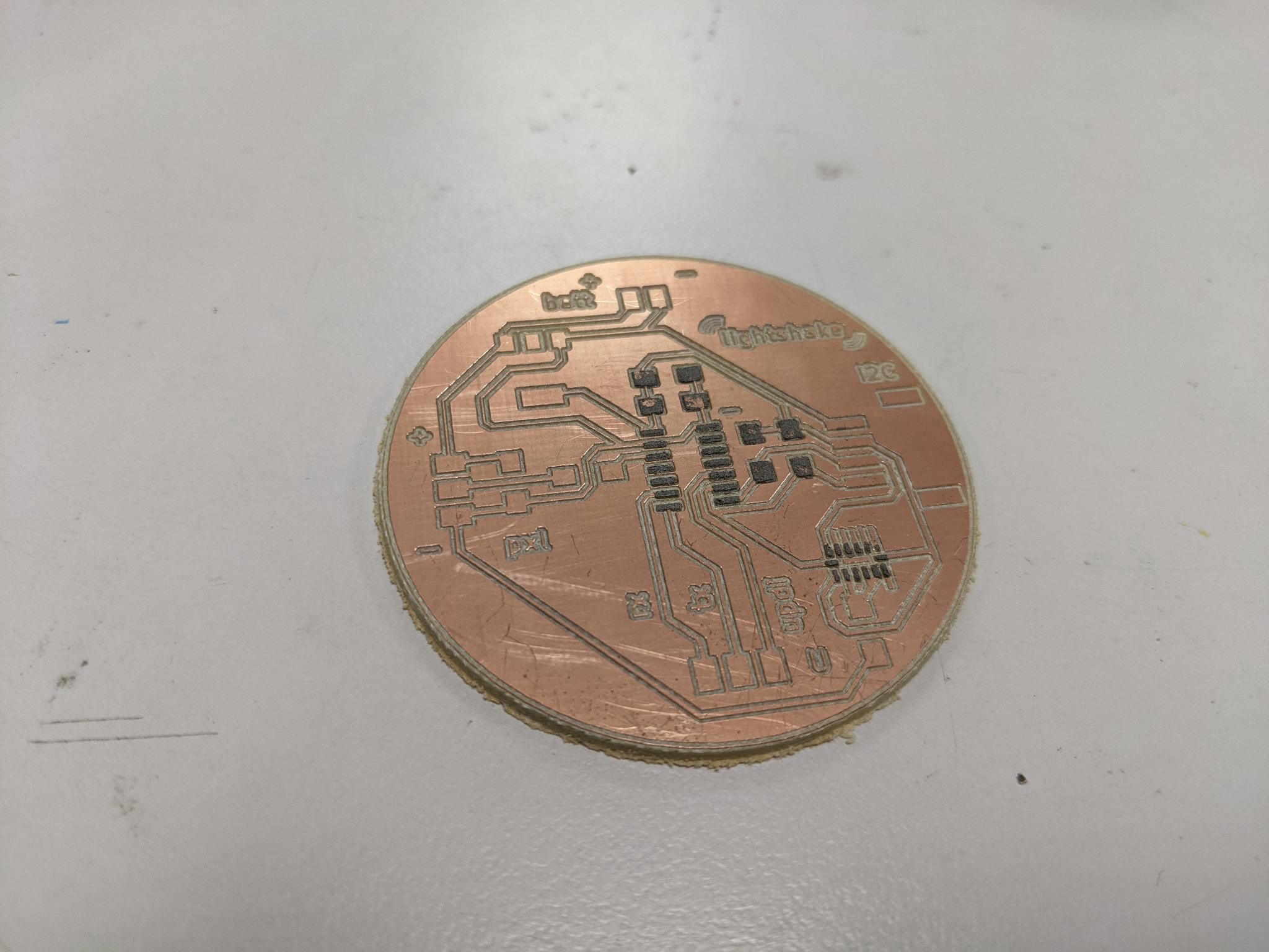
Mill
At first I tought of using a 0.4 mm mill to trace the tracks, but the pads of the AXL343 are too close for that. So I used a V-shape mill (for the first time !).
- I carefully zeroed the mill on the top copper surface, almost ten times, to really be sure to set zero on the lowest point.
- I entered 0.2 diameter mill in FlatCam with the following parameters:
- Cut Z : -0.06 mm
- Travel Z : 2
- End move Z : 15
- Feedrate X-Y : 180 mm/min
- Feedrate Z : 100 mm/min
- Spindle speed : 8000 tours/min
I was impressed by the speed of it, compared to the cylindric ones!
Everything went fine. When I had to mill a second board I was less lucky with the z-level of the copper plate and the traces were more irregular but they still worked though.
- I did the edge cutting with a 2mm cylindric mill, same parameter as in Electronics production.
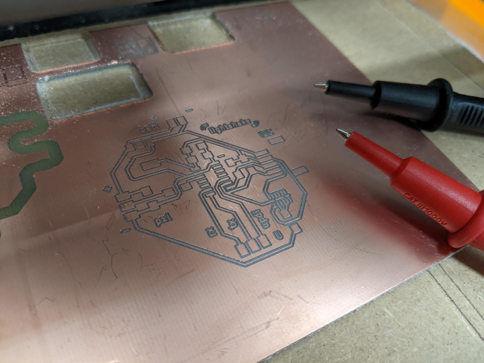
Solder paste and paper mask
As the ADXL343 package is really small AND has its pads underneath the component, I had to use solder paste. To be sure to put solder paste only on the pads, I used a paper mask etched with the laser cutting machine
To create the paper mask:
- In Kicad, plot the layer F.Paste in
.svg. Be sure to also tick to add Edge cuts on the file.
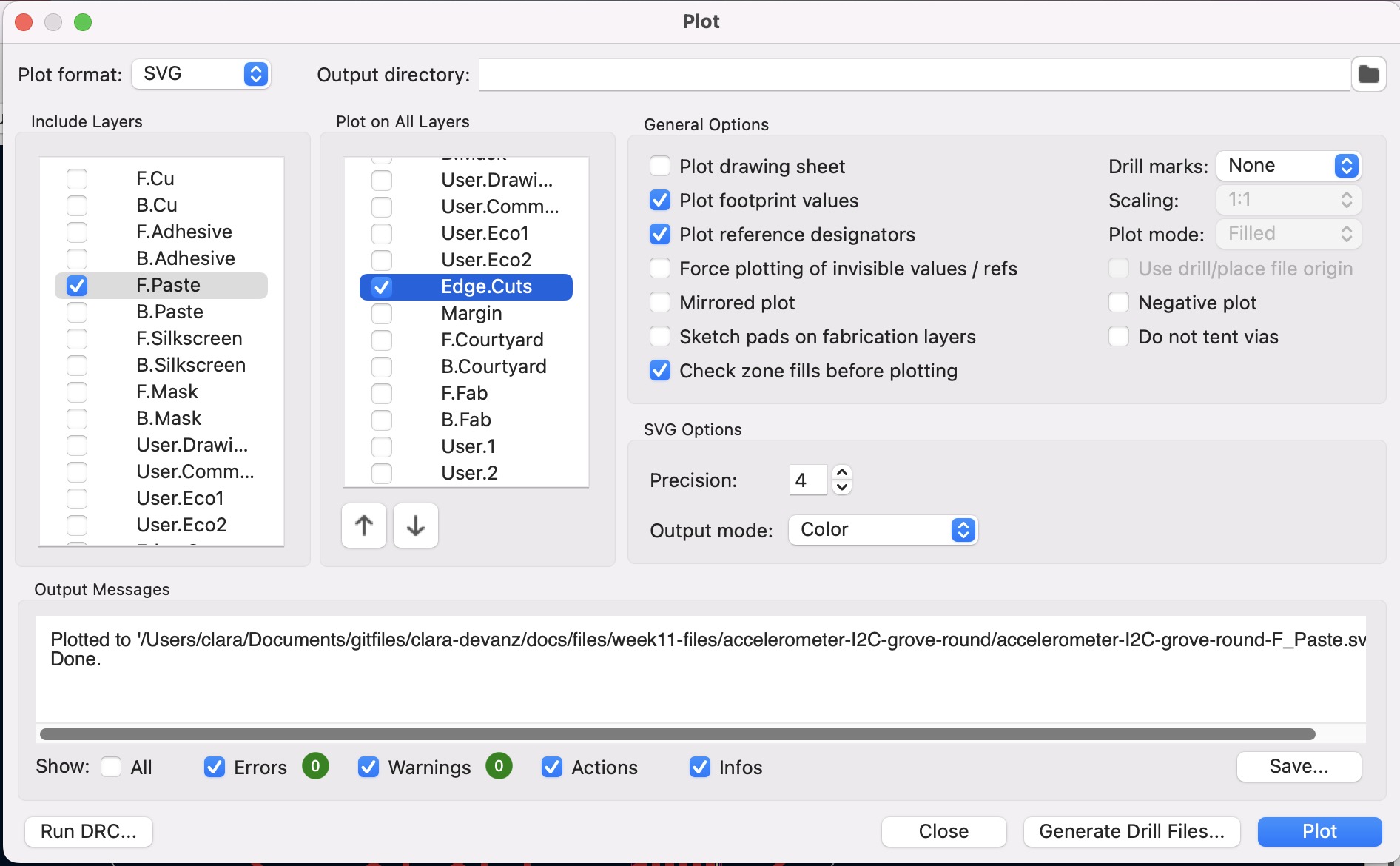
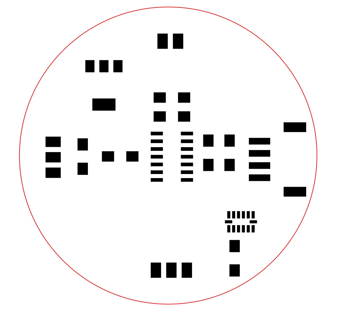
- In Inkscape, change the fill and outline properties for laser cutting process: engrave the pads and cut the edges. In our case engraving is black filling and cutting red outline. We engrave the pads and not cut their outlines because it allows us to have a better fidelity to the pads dimensions.
- Tape the paper to a mdf sacrificial board. I used a white paper with a thickness of 120g/m2.
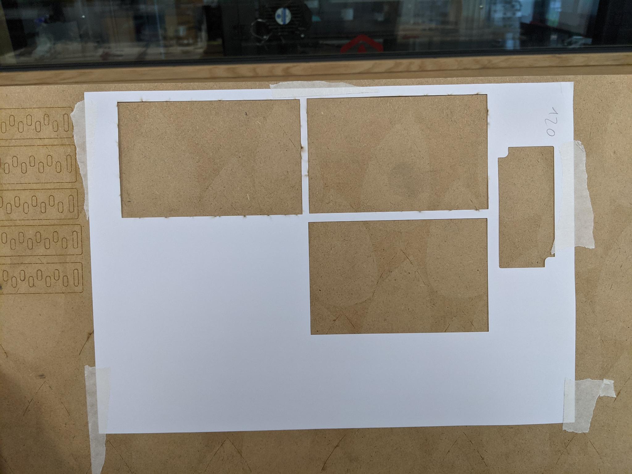
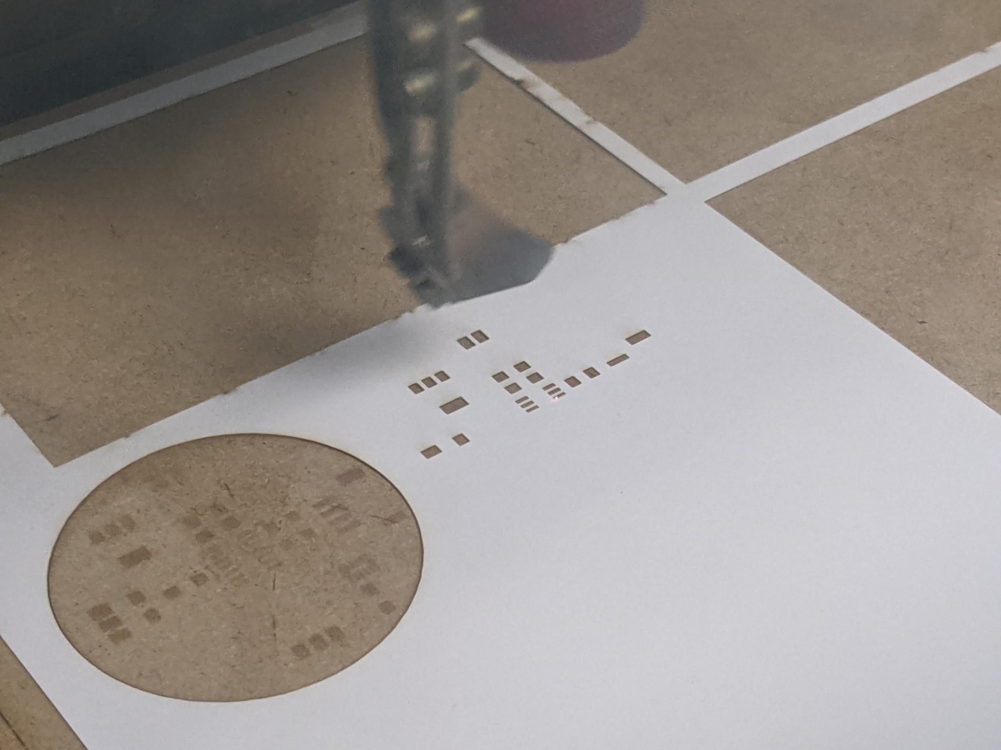
-
Launche the job on the laser cutting machine. I used the trotec Speedy 100 because it's the machine my colleague had done its settings for. The parameters are the following:
- Cutting: 32% Power, 5% Speed, 2 passes
- Engraving: 20% Power, 10% Speed, 1 pass
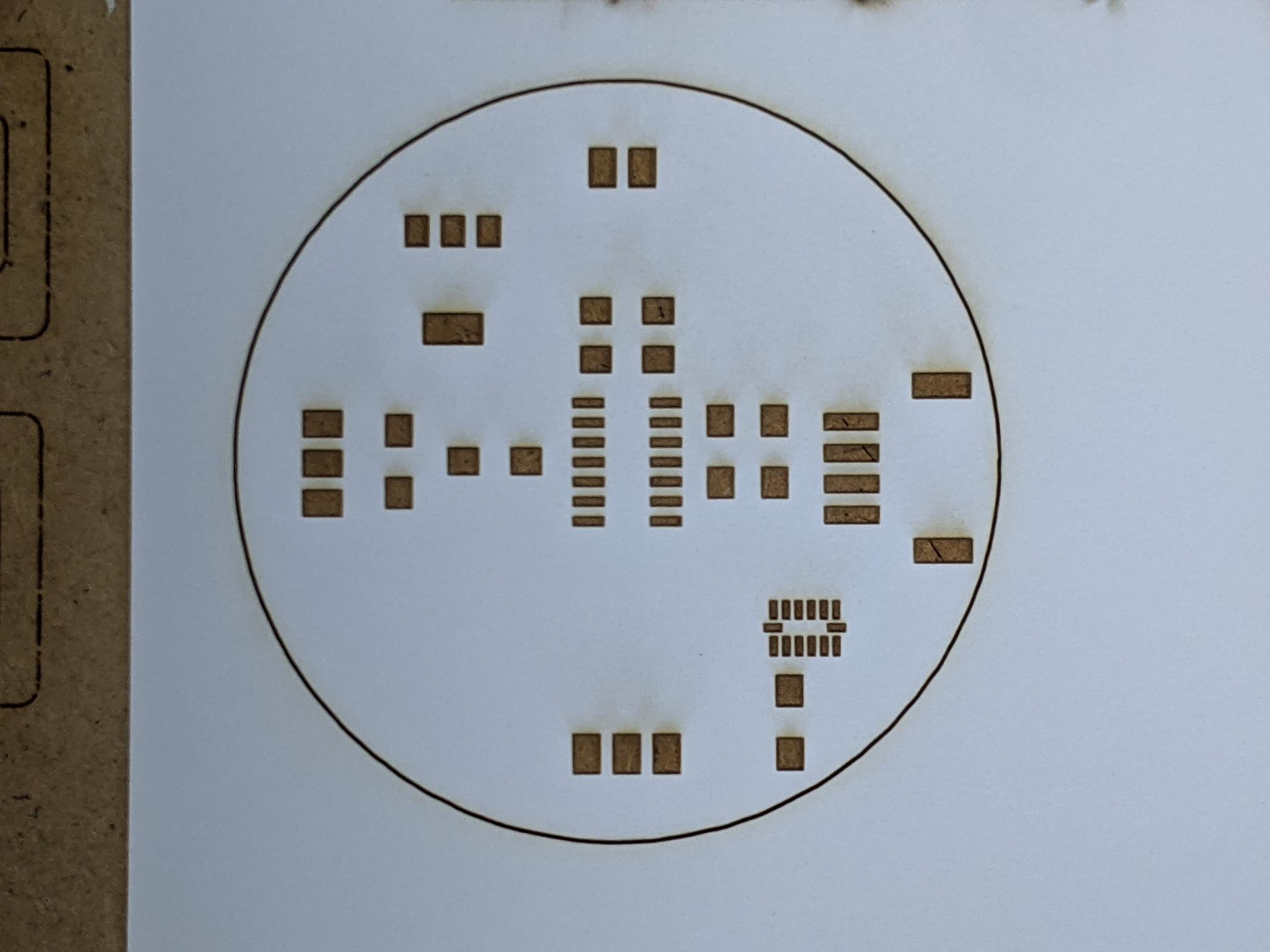
Once you have your paper mask, gather all the material:
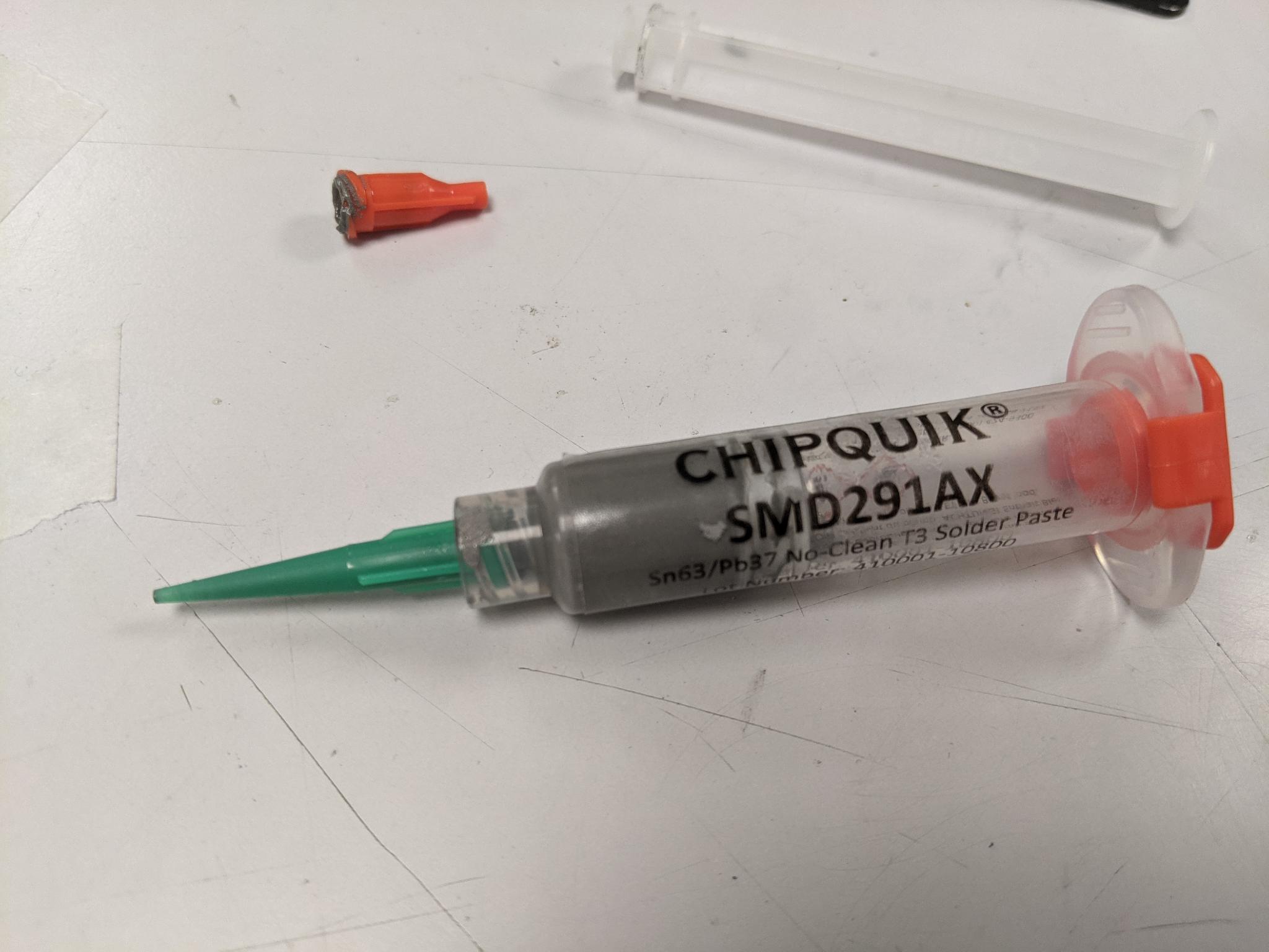
- Solder paste (you have to store it in the fridge) with all its accessories: plastic push syringe, fine tips...
- A piece of flexible plastic (such as thin PP) to spread the paste
- Tape to attach the mask and PCB to the table
- A heat gun
- The component(s) you'll solder (in my case the ADXL343)
- Small pliers
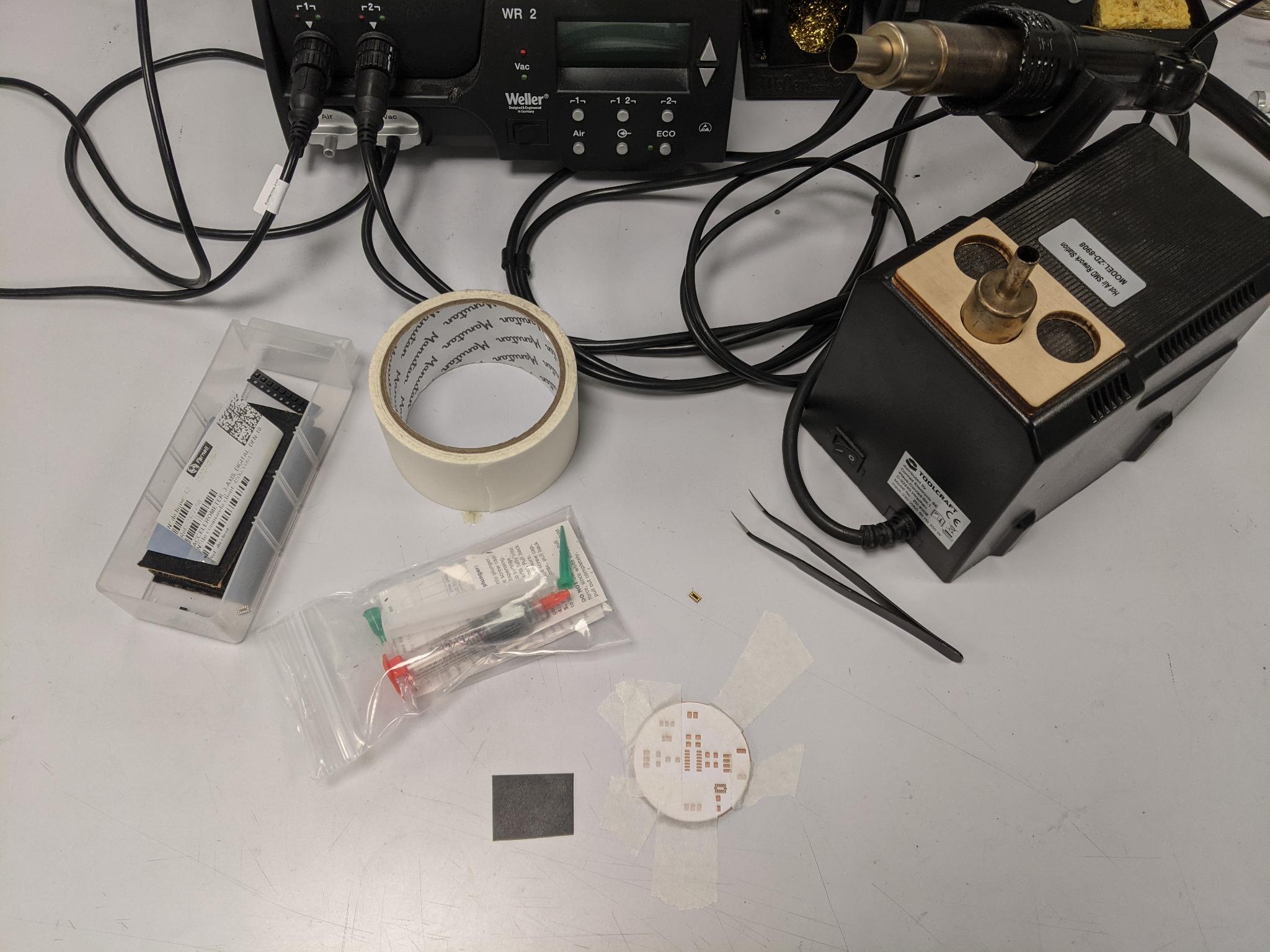
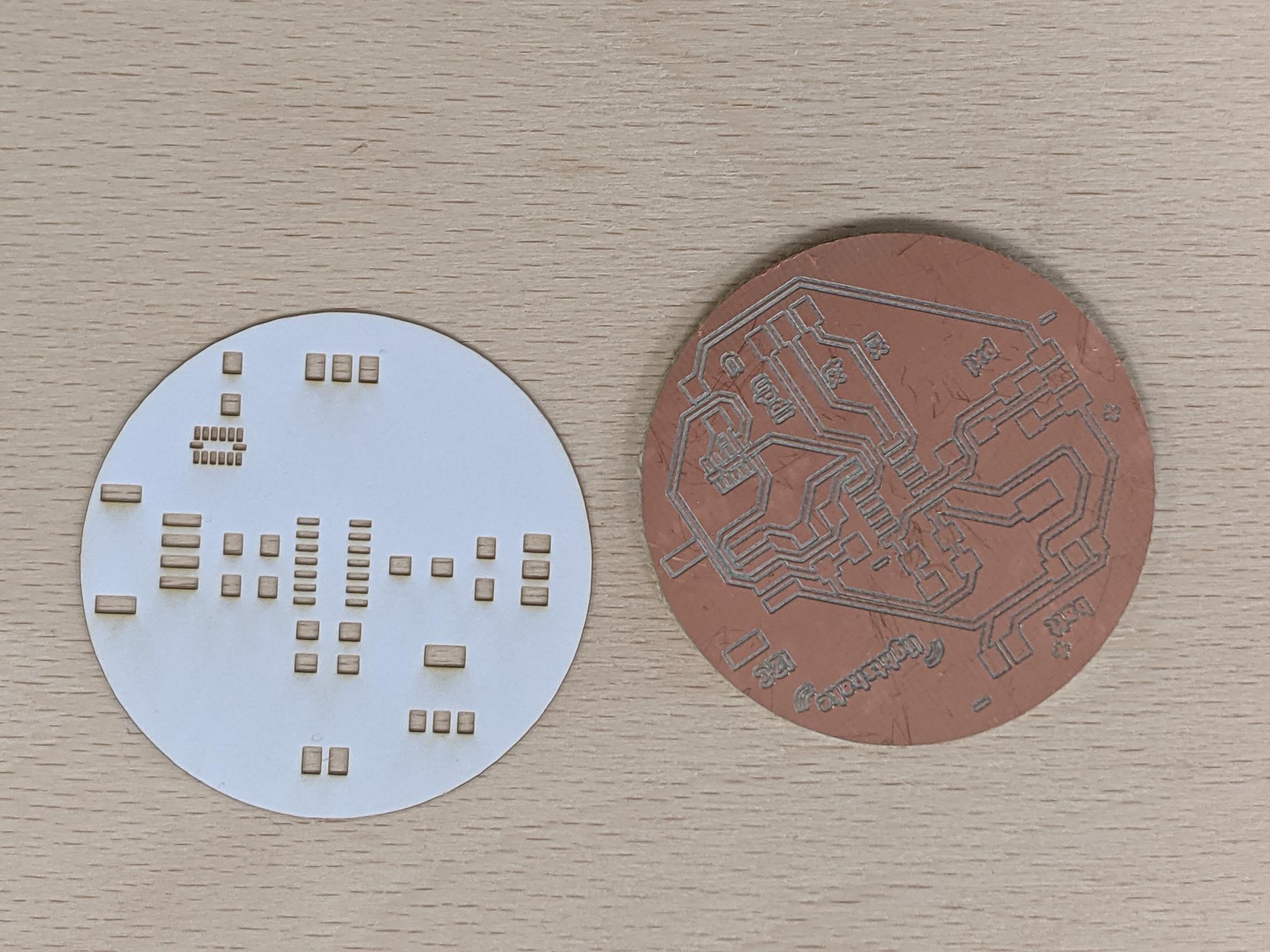
Place the mask precisely on top the PCB and tape it to the table (my PCB stuck to the table because there was still double-sided tape from the milling process). Open the solder paste tube and screw the tip.
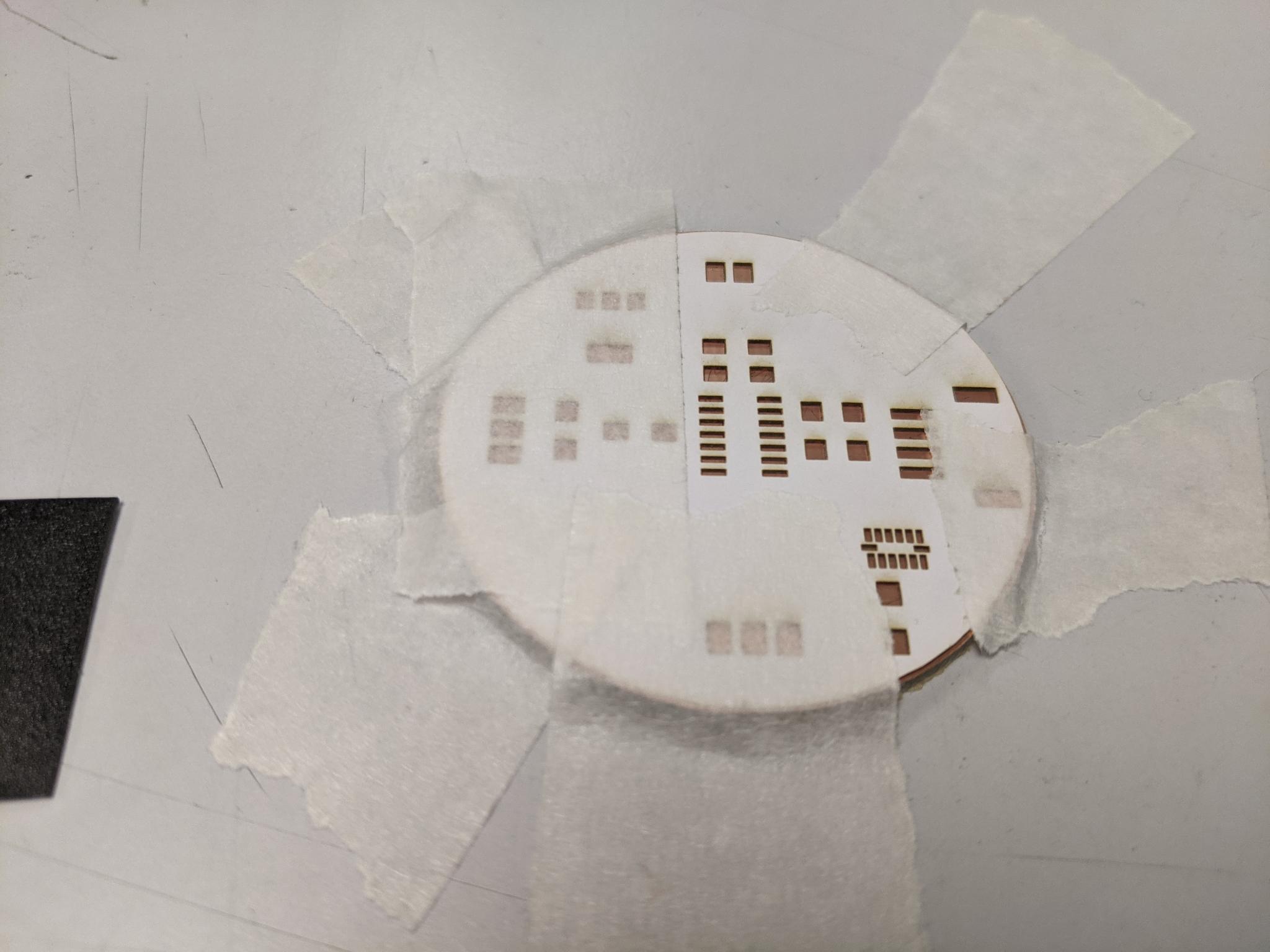
Spread the solder paste through the mask with the flexible piece of plastic. Take off the mask carefully.
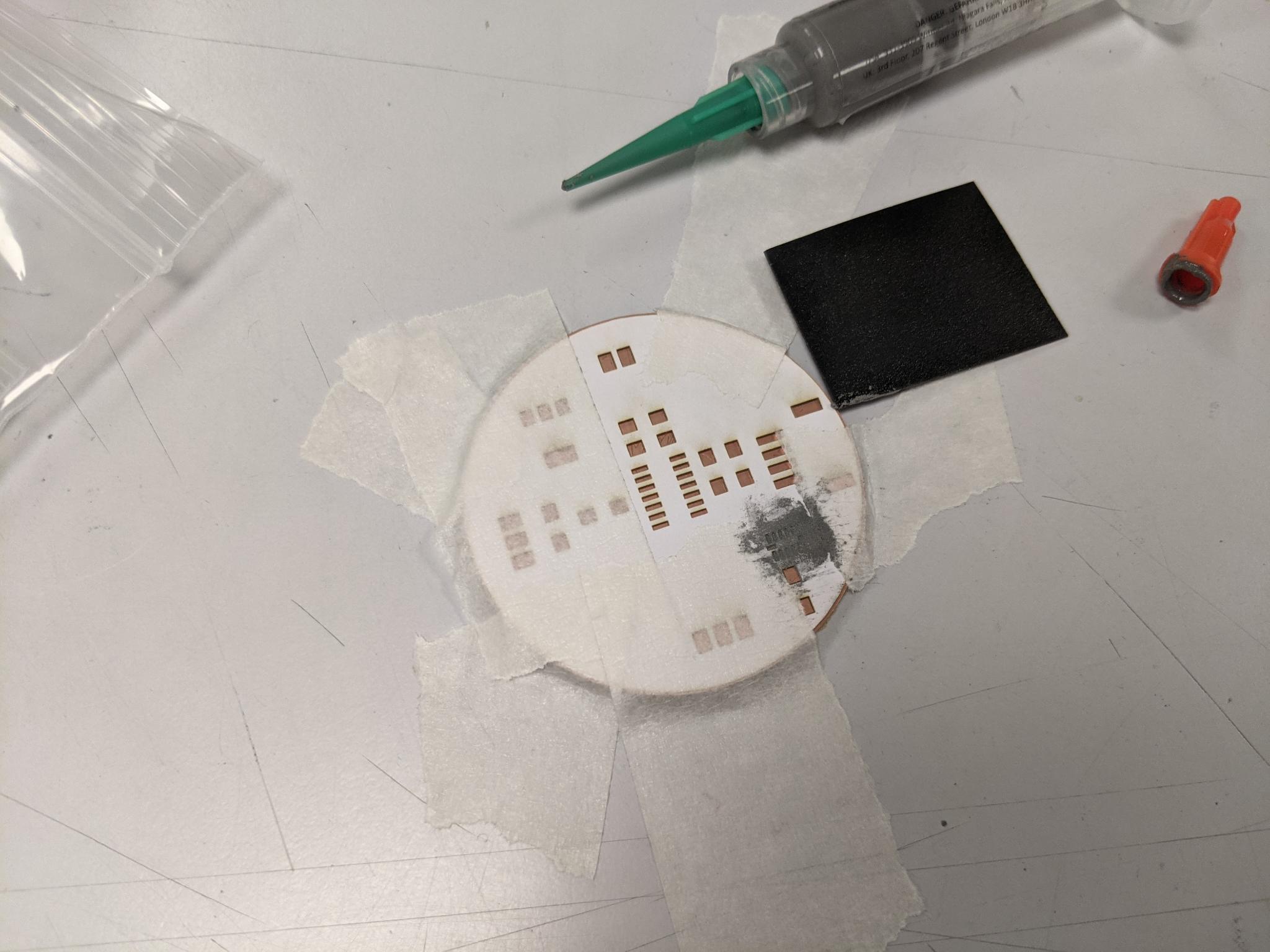
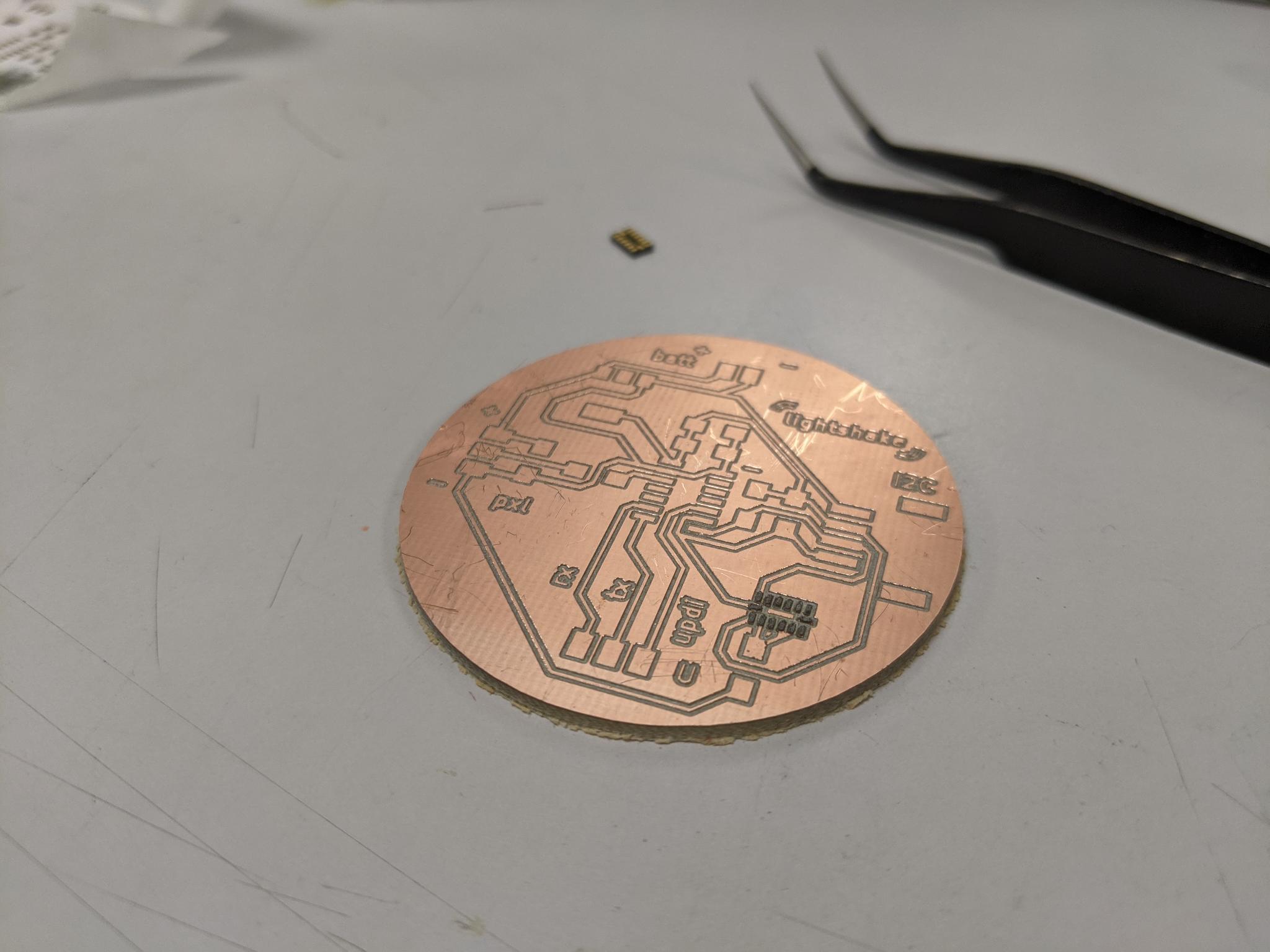
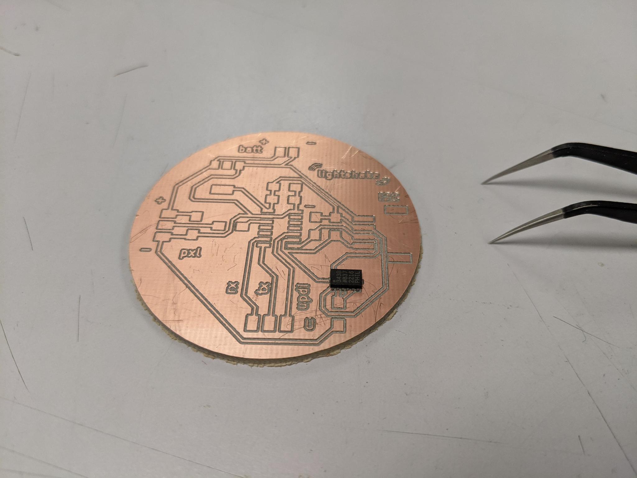
Place delicately the component on the solder paste.
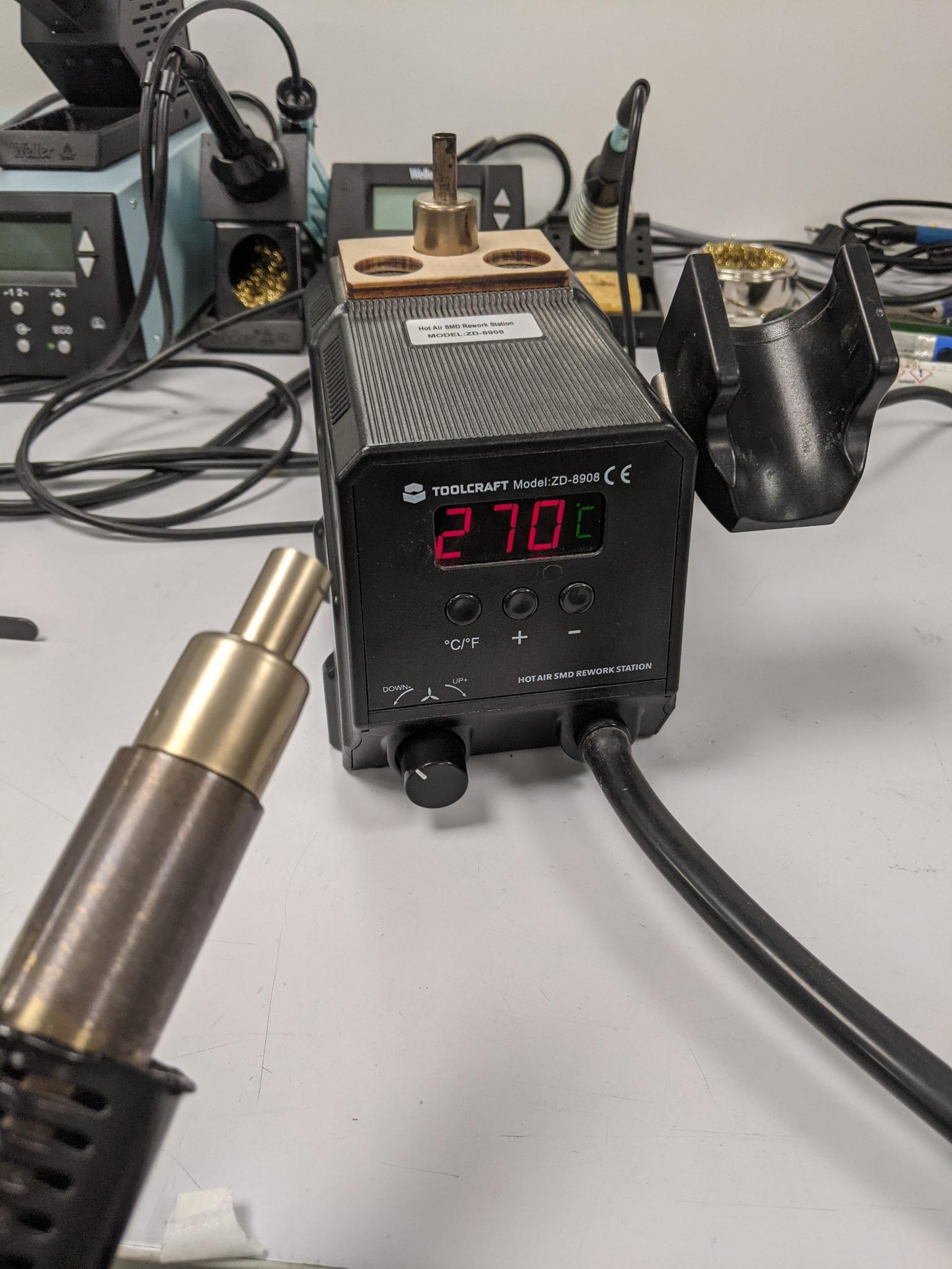
Change the heat gun tip for a large one, then heat the heat gun to a high temperature near 270°C. Approch it slowly from above to your component. Keep the heat gun above the component until you see the paste starting to melt and shine.
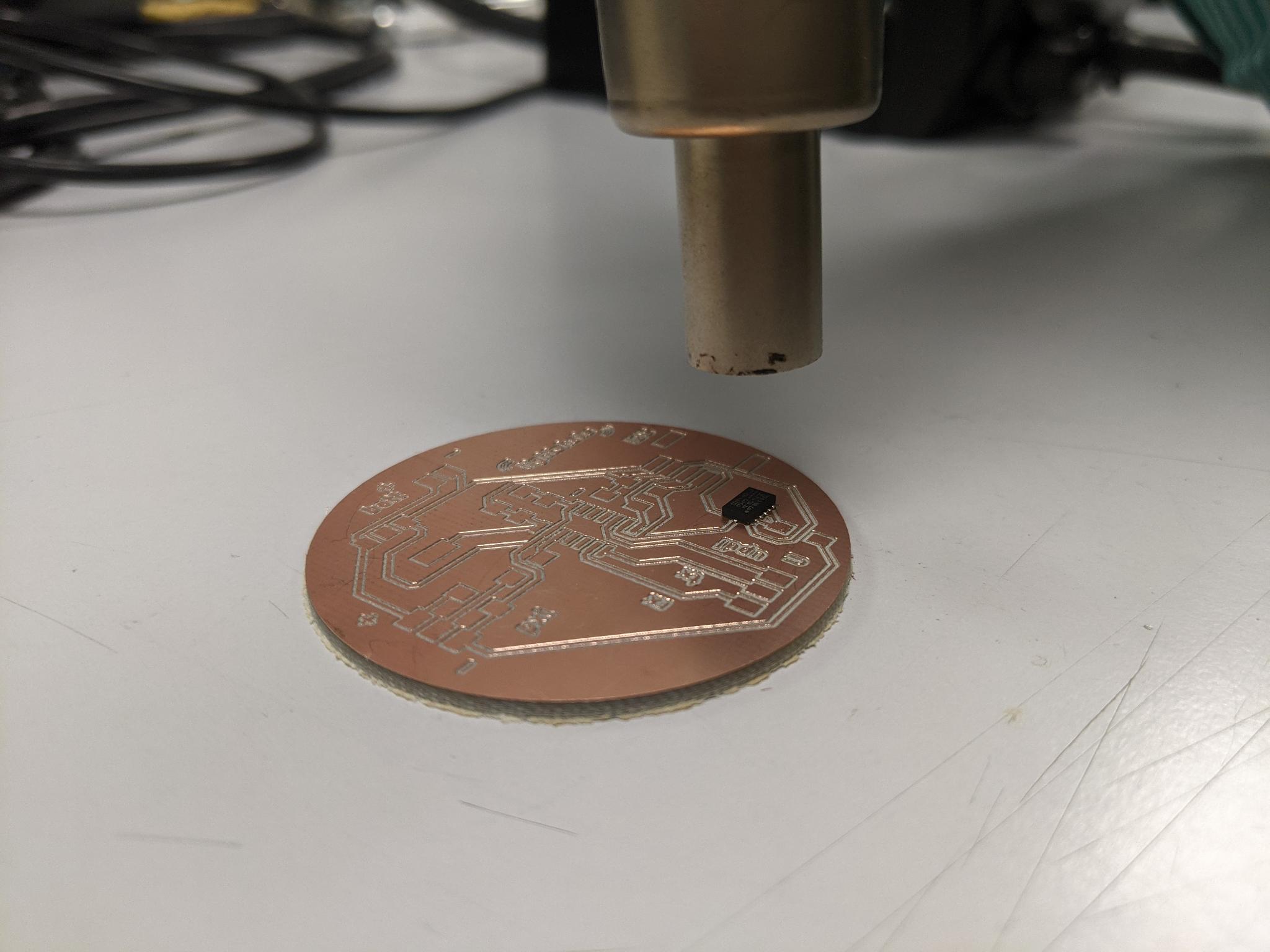
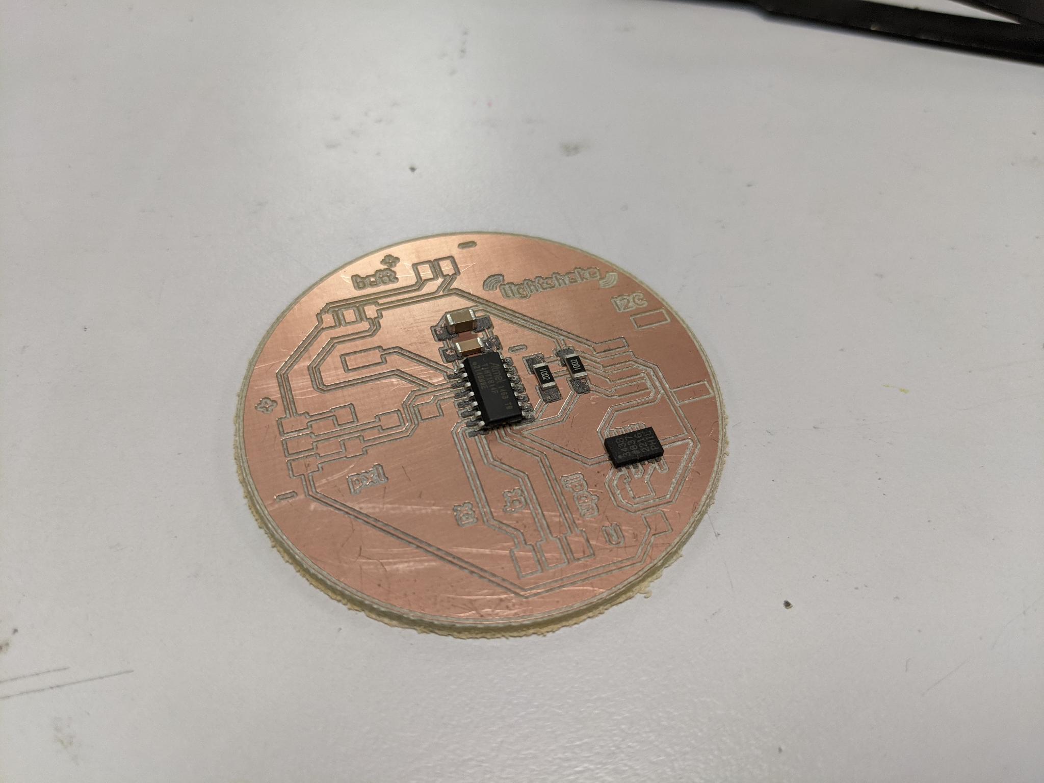
Done ! Check for short circuits. I soldered the other (way bigger) components by hand.
Software side
I first checked that I could program my board with UPDI. Don't forget to also connect the ground reference!! And the Vcc if you want anything to happen.
I could light up a led strip, so success for that step!
I also tested the serial communication by connecting Rx and Tx. I had some challenges here, inverted Rx and Tx and eventually managed to have some information in the serial monitor.
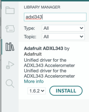
Then in order to use the ADXL I downloaded the Adafruit_ADXL343.h library, along with the depedencies Adafruit Unified Sensor and Adafruit BusIO. I already had installed Wire.h that you need for I2C communication.
But then I was really lost.
ADXL issues
Confident that the hardware was working fine, I tried programming the accelerator ADXL343 but was quite lost in the examples. I tried reading the code provided by Neil but it was way too low level from what I was used to code (also he used another ATtiny than me). I got quite upset about the lack of guidance about that component even if it was on the fabacademy list of material.
I browsed the documentation of other students to realise I had missed an important point of the documentation, that is that the ADXL pin CS must be connected to VDD in order to use it with I2C. My bad, I was too quick on my wiring!
Instructor's advice: When you have such a component with the pads hidden underneath, trace some tracks going a bit further out for each pin, if you have to hand wire anything afterwards.
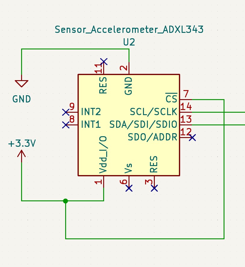
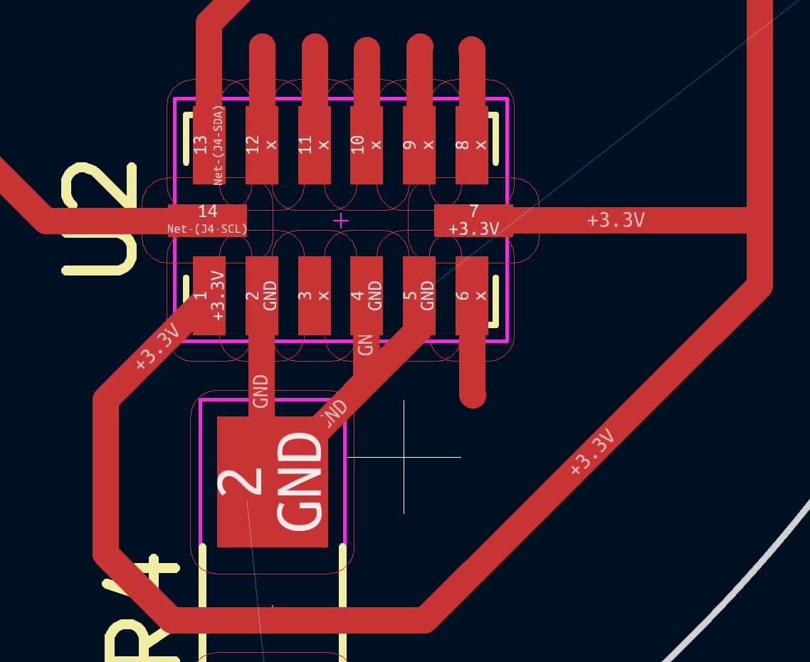
I2C pinout
As mentionned in the datasheet, in order to allow the I2C protocol on the ADXL343, CS needs to be connected to VDD. I thus modified my design.
I then milled it. The horizontality was worse than for the first board but I somehow managed to mill the tracks correctly. Let's go back to paper mask, solder paste, hand soldering...
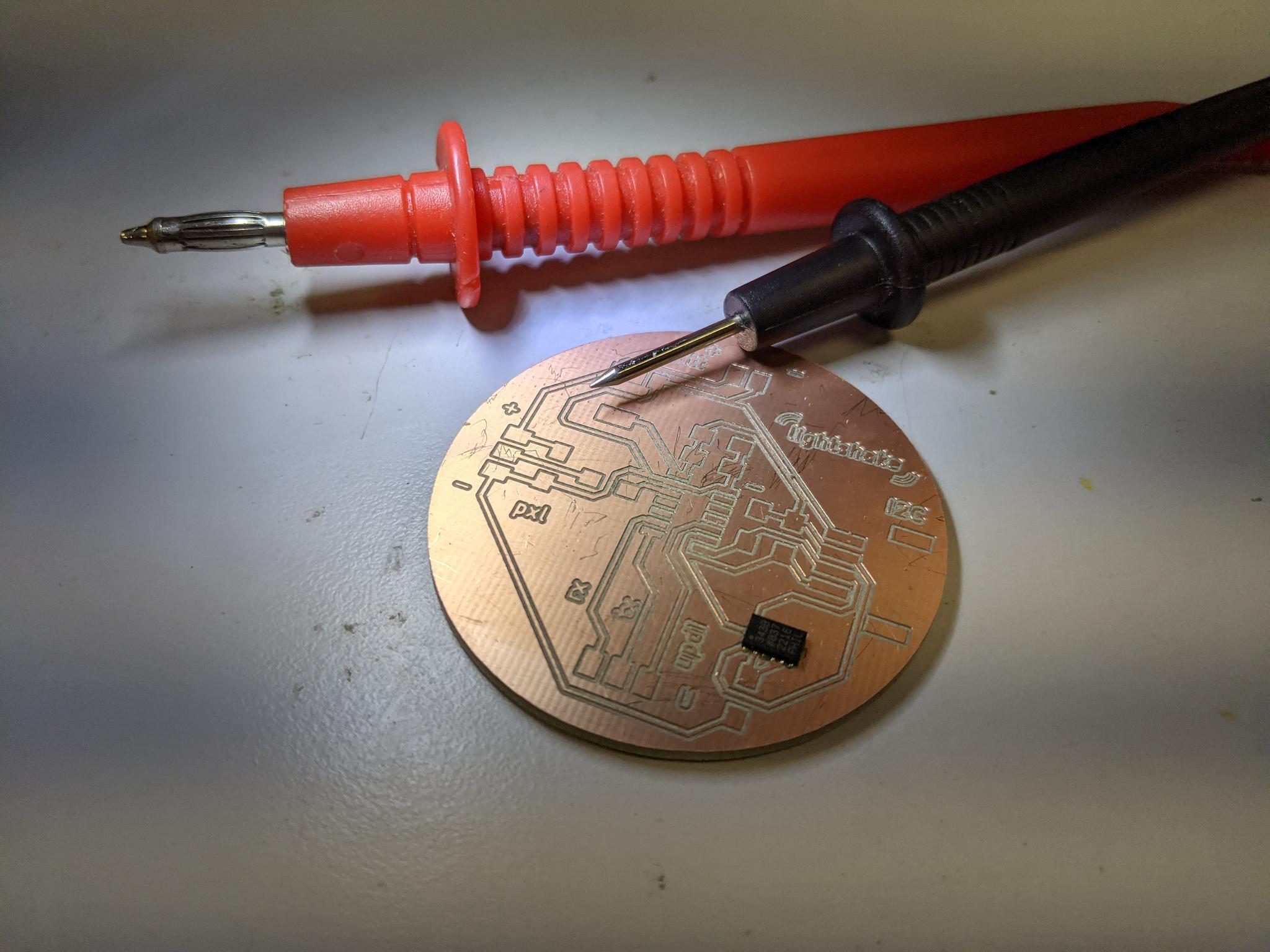
Short circuits?
Unfortunately I couldn't obtain any result with this new board. As suggested my instructor I ran an I2C-scanner script to check if anything is plugged in I2C. My AXL343 is supposed to be on the I2C bus so it should appear. But obviously it's not the case, so there's probably an hardware issue such as a short circuit.

Well I'll move on for this week to an easier component (hardware and software speaking).
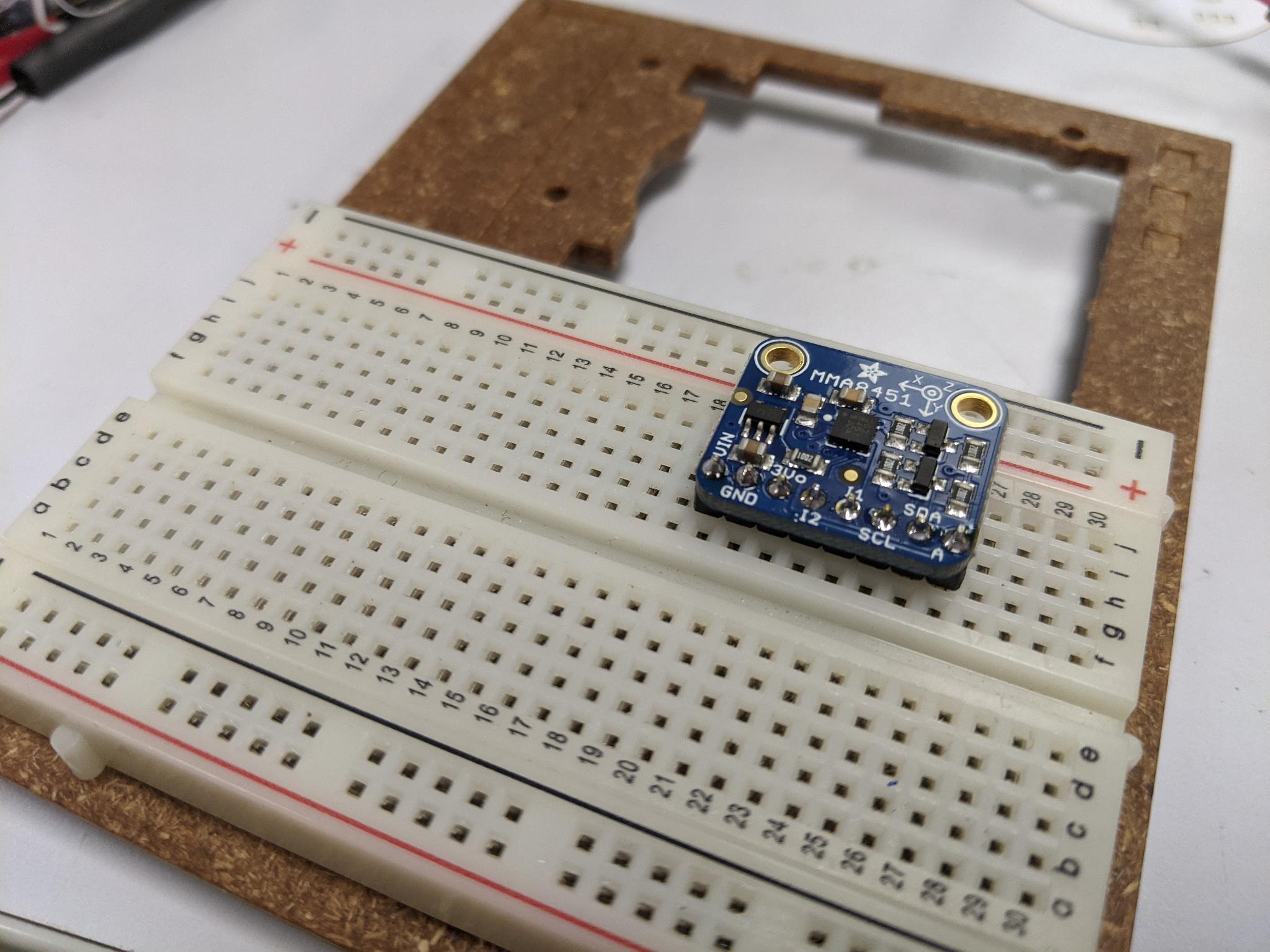
MMA8458 breakout board
Getting started
I then decided to use the MMA8458 Adafruit's breakout board, which also features a 3-axis accelerometer and I2C communication. For the hardware it was pretty straight forward as I had provided an I2C grove connector on my board. I just had to solder the pins to the breakout board. To do this you use a breadboard to hold the pins vertically, then classic hand soldering.
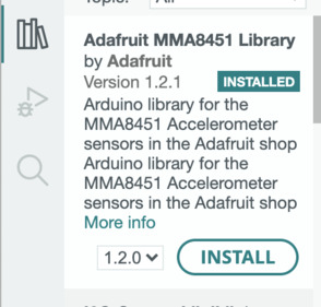
I started by downloading the Adafruit_MMA8451.h library.
If you haven't done it before you should check that you also have Wire.h library installed for I2C communication and Adafruit_Sensor.h for unified sensor functions and tinyNeoPixel.h library if you plan to use neopixel strips like me.
I uploaded successefully the MMA8451demo example provided with the library. It sends information about the axis orientation in the serial monitor, according to the orientation of the breakout board.
Serial communication remarks: Don't forget to switch port from UPDI to FTDI to read the information in the serial port. Also you might need to invert Rx and Tx wire if it doesn't work the first time
Here's an example of what's printed in the serial monitor:
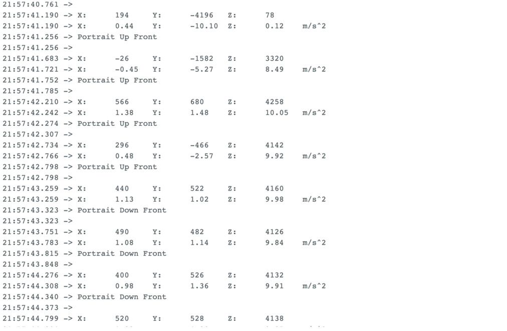
You can read more about the parameters retrieved and how they're processed in the library file Adafruit_MMA8451.h
For example the library defines different orientation presets:
#define MMA8451_PL_PUF 0
#define MMA8451_PL_PUB 1
#define MMA8451_PL_PDF 2
#define MMA8451_PL_PDB 3
#define MMA8451_PL_LRF 4
#define MMA8451_PL_LRB 5
#define MMA8451_PL_LLF 6
#define MMA8451_PL_LLB 7
In the example code they're named this way:
  switch (o) {
    case MMA8451_PL_PUF:
      Serial.println("Portrait Up Front");
      break;
    case MMA8451_PL_PUB:
      Serial.println("Portrait Up Back");
      break;
    case MMA8451_PL_PDF:
      Serial.println("Portrait Down Front");
      break;
    case MMA8451_PL_PDB:
      Serial.println("Portrait Down Back");
      break;
    case MMA8451_PL_LRF:
      Serial.println("Landscape Right Front");
      break;
    case MMA8451_PL_LRB:
      Serial.println("Landscape Right Back");
      break;
    case MMA8451_PL_LLF:
      Serial.println("Landscape Left Front");
      break;
    case MMA8451_PL_LLB:
      Serial.println("Landscape Left Back");
      break;
    }
I slightly adapted this example code to trigger the fact that a neopixel strip connected to port PA5 will light up if in two particular orientations ("Landscape Left Front" and "Landscape Right Front").
    case MMA8451_PL_LRF:
      Serial.println("Landscape Right Front");
      for (int i = 0; i < NUMPIXELS; i++) {
        // pixels.Color takes RGB values, from 0,0,0 up to 255,255,255
        strip.setPixelColor(i, strip.Color(r, g, b)); // Moderately bright green color.
        strip.show(); // This sends the updated pixel color to the hardware.
        delay(delayval); // Delay for a period of time (in milliseconds).
      }
Here's a short video demonstrating this example:
Getting familiar with the axis informations
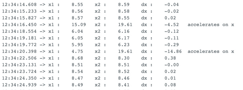
I wanted to detect significative movement, such as when one shakes the accelerometer. I started by detecting siginficative variations along the x-axis by introducing x1 and x2 which are two measures of x delayed by a few milliseconds. I thus calculate the difference dx. The value of dx will trigger specific actions if above a certain value:
  float x1;
  float x2;
  float dx;
  mma.read();
  sensors_event_t event;
  mma.getEvent(&event);
  x1 = event.acceleration.x;
  delay (50);
  mma.read();
  mma.getEvent(&event);
  x2 = event.acceleration.x;
  delay (50);
  dx = x1-x2;
Here's what we have when we ask to print x1, x2 and dx and sets a minimum absolute value of 2 to print a message "accelerates on x"
Here's the full code that lights up the led strip when significant change on x-axis is detected:
#include <Wire.h>
#include <Adafruit_MMA8451.h>
#include <Adafruit_Sensor.h>
#include <tinyNeoPixel.h>

#define STRIP           1 // PA5 on lightshake
#define NUMPIXELS      10

tinyNeoPixel strip = tinyNeoPixel(NUMPIXELS, STRIP, NEO_GRBW + NEO_KHZ800);
int delayval = 50;

Adafruit_MMA8451 mma = Adafruit_MMA8451();

void setup(void) {

  strip.begin(); // This initializes the NeoPixel library.
  strip.clear();
  delay(delayval); // Delay for a period of time (in milliseconds).

  Serial.begin(9600);
  Serial.println("Adafruit MMA8451 test!");

  if (! mma.begin()) {
    Serial.println("Couldnt start");
    while (1);
  }
  Serial.println("MMA8451 found!");

  mma.setRange(MMA8451_RANGE_2_G);

  Serial.print("Range = "); Serial.print(2 << mma.getRange());
  Serial.println("G");

}

void loop() {
  mma.read();
  sensors_event_t event;
  mma.getEvent(&event);
  //uint8_t o = mma.getOrientation();
  float x1;
  float x2;
  float dx;

  x1 = event.acceleration.x;
  Serial.print("x1 : \t"); Serial.print(x1); Serial.print("\t");
  delay (50);
  mma.read();
  mma.getEvent(&event);
  x2 = event.acceleration.x;
  Serial.print("x2 : \t"); Serial.print(x2); Serial.print("\t");
  delay (50);
  dx = x1-x2;
  Serial.print("dx : \t"); Serial.print(dx); Serial.print("\t");

  if (abs(dx)>=2){
    Serial.print("accelerates on x");
    turnOnAllStrip(255,0,0);
    }

  else {
    turnOffAllStrip();
  }
  Serial.println();
  delay(500);

}

void turnOnAllStrip(int r, int g, int b){
  for (int i=0;i<NUMPIXELS;i=i+1){
  strip.setPixelColor(i, strip.Color(r, g, b));
  strip.show();
  delay(delayval);
}
delay(1000);
}

void turnOffAllStrip(){
  for (int i=0;i<NUMPIXELS;i=i+1){
  strip.setPixelColor(i, strip.Color(0, 0, 0));
  strip.show();
}
}
And here's a code to detect significant change on all three axis.
- The led strip turns red when there's a significant change on the x-axis (
abs(dx)>10) - The led strip turns green when there's a significant change on the y-axis (
abs(dy)>10) - The led strip turns blue when there's a significant change on the z-axis (
abs(dx)>10)
#include <Wire.h>
#include <Adafruit_MMA8451.h>
#include <Adafruit_Sensor.h>
#include <tinyNeoPixel.h>

#define STRIP           1 // PA5 on lightshake
#define NUMPIXELS      10

tinyNeoPixel strip = tinyNeoPixel(NUMPIXELS, STRIP, NEO_GRBW + NEO_KHZ800);
int delayval = 50;

Adafruit_MMA8451 mma = Adafruit_MMA8451();

void setup(void) {

  strip.begin(); // This initializes the NeoPixel library.
  strip.clear();
  delay(delayval); // Delay for a period of time (in milliseconds).

  Serial.begin(9600);
  Serial.println("Adafruit MMA8451 test!");

  if (! mma.begin()) {
    Serial.println("Couldnt start");
    while (1);
  }
  Serial.println("MMA8451 found!");

  mma.setRange(MMA8451_RANGE_2_G);

  Serial.print("Range = "); Serial.print(2 << mma.getRange());
  Serial.println("G");

}

void loop() {
  mma.read();
  sensors_event_t event;
  mma.getEvent(&event);
  //uint8_t o = mma.getOrientation();
  float x1;
  float x2;
  float dx;

  float y1;
  float y2;
  float dy;

  float z1;
  float z2;
  float dz;

  int dx_trig = 10;
  int dy_trig = 10;
  int dz_trig = 10;

  x1 = event.acceleration.x;
  y1 = event.acceleration.y;
  z1 = event.acceleration.z;

  Serial.print("x1 : \t"); Serial.print(x1); Serial.print("\t");
  Serial.print("y1 : \t"); Serial.print(y1); Serial.print("\t");
  Serial.print("z1 : \t"); Serial.print(z1); Serial.print("\t");

  delay (50);

  mma.read();
  mma.getEvent(&event);

  x2 = event.acceleration.x;
  y2 = event.acceleration.y;
  z2 = event.acceleration.z;

  Serial.print("x2 : \t"); Serial.print(x2); Serial.print("\t");
  Serial.print("y2 : \t"); Serial.print(y2); Serial.print("\t");
  Serial.print("z2 : \t"); Serial.print(z2); Serial.print("\t");

  delay (50);

  dx = x1-x2;
  dy = y1-y2;
  dz = z1-z2;

  Serial.print("dx : \t"); Serial.print(dx); Serial.print("\t");
  Serial.print("dy : \t"); Serial.print(dy); Serial.print("\t");
  Serial.print("dz : \t"); Serial.print(dz); Serial.print("\t");

  if (abs(dx)>=dx_trig){
    Serial.print("accelerates on x");
    turnOnAllStrip(255,0,0);
    }

  if (abs(dy)>=dy_trig){
    Serial.print("accelerates on y");
    turnOnAllStrip(0,255,0);
    }

  if (abs(dz)>=dz_trig){
    Serial.print("accelerates on z");
    turnOnAllStrip(0,0,255);
    }

  else if (abs(dx)<=dx_trig && abs(dy)<=dy_trig & abs(dz)<=dz_trig){
    turnOffAllStrip();
  }
  Serial.println();
  delay(500);

}

void turnOnAllStrip(int r, int g, int b){
  for (int i=0;i<NUMPIXELS;i=i+1){
  strip.setPixelColor(i, strip.Color(r, g, b));
  strip.show();
  delay(delayval);
}
delay(1000);
}

void turnOffAllStrip(){
  for (int i=0;i<NUMPIXELS;i=i+1){
  strip.setPixelColor(i, strip.Color(0, 0, 0));
  strip.show();
}
}
On the following videos you can see x-axis acceleration variations in red, y-axis in green and z-axis in blue (second video):
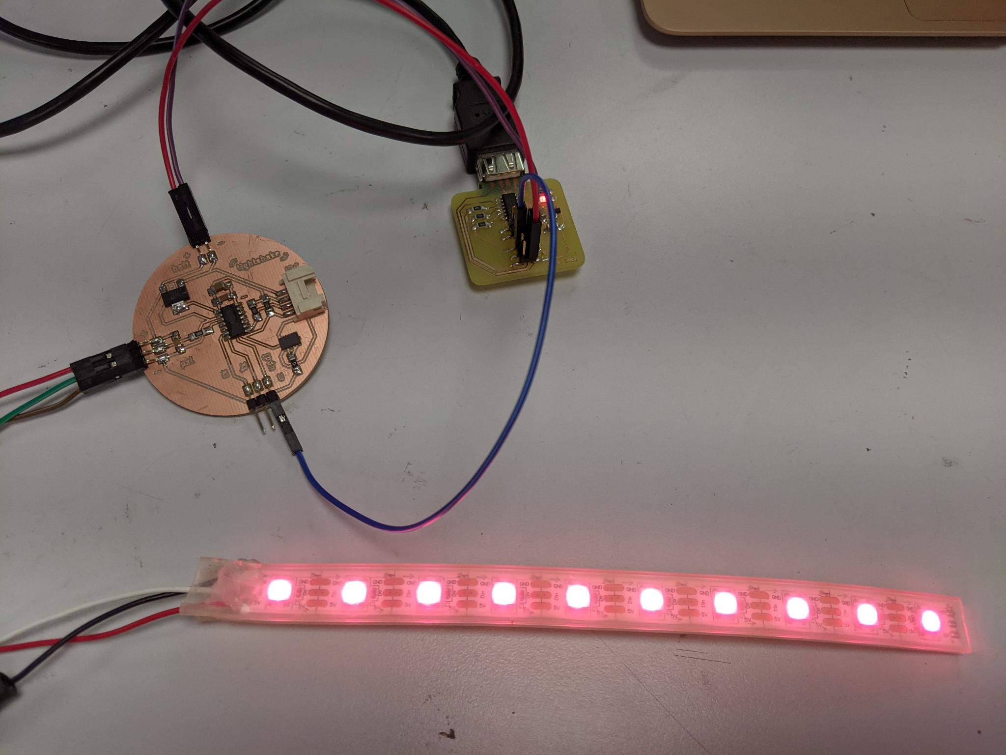
Demo circuit with led strip
For my application I don't really care about which axis presents a significant change and rather want to detect a shaking movement. I'll have two different colors at the two ends of my strip and I want to blend the two colors when I shake the led tube
Color coding
I didn't succeed from the first attempt to have a nice color gradient, as I was introducing too many parameters comparing RGB values of one tip and the other.
One of the attempt:
The formula was in fact way simpler. Let's say that the initial state of the led strip is given by:
  strip.setPixelColor(0, strip.Color(rA, gA, bA));
  strip.setPixelColor(NUMPIXELS-1, strip.Color(rB, gB, bB));
  strip.show();
Finally the way to have a nice gradient is this piece of code:
 int r; int g; int b;
    int p = 1;

    for (int i=1;i<NUMPIXELS-1;i=i+1)
      {
      r = rA + p*(rB-rA)/NUMPIXELS;
      g = gA + p*(gB-gA)/NUMPIXELS;
      b = bB + p*(bB-bA)/NUMPIXELS;

      strip.setPixelColor(i, strip.Color(r, g, b));
      strip.show();
      p=p+1;
     }
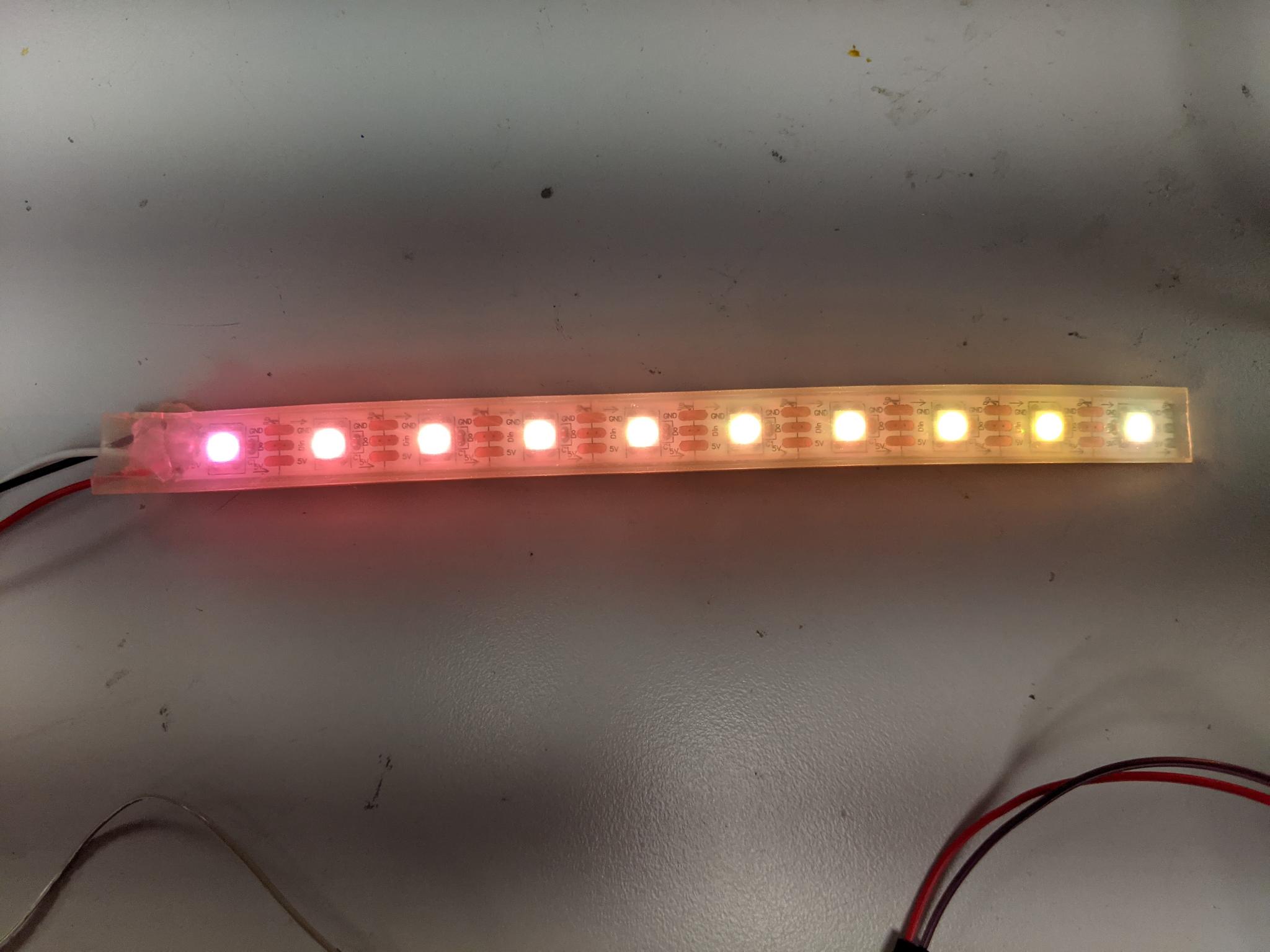
Here's a picture of a successfull gradient:
Code
The whole code with serial prints to check everything is fine is the following:
#include <Wire.h>
#include <Adafruit_MMA8451.h>
#include <Adafruit_Sensor.h>
#include <tinyNeoPixel.h>

#define STRIP           1 // PA5 on lightshake
#define NUMPIXELS      10

tinyNeoPixel strip = tinyNeoPixel(NUMPIXELS, STRIP, NEO_GRBW + NEO_KHZ800);
int delayval = 50;

int rA = 220; int gA = 30; int bA = 20;
int rB = 120; int gB = 80; int bB = 10;

Adafruit_MMA8451 mma = Adafruit_MMA8451();

void setup(void) {

  strip.begin(); // This initializes the NeoPixel library.
  strip.clear();

  Serial.begin(9600);
  Serial.println("Adafruit MMA8451 test!");

  if (! mma.begin()) {
    Serial.println("Couldnt start");
    while (1);
  }
  Serial.println("MMA8451 found!");

  mma.setRange(MMA8451_RANGE_2_G);

  Serial.print("Range = "); Serial.print(2 << mma.getRange());
  Serial.println("G");

  for (int i=1;i<NUMPIXELS-1;i=i+1){
  strip.setPixelColor(i, strip.Color(0, 0, 0));
  strip.show();
  }
  strip.setPixelColor(0, strip.Color(rA, gA, bA));
  strip.setPixelColor(NUMPIXELS-1, strip.Color(rB, gB, bB));
  strip.show();

}

void loop() {

  mma.read();
  sensors_event_t event;
  mma.getEvent(&event);
  //uint8_t o = mma.getOrientation();
  float x1;
  float x2;
  float dx;

  float y1;
  float y2;
  float dy;

  float z1;
  float z2;
  float dz;

  int dx_trig = 10;
  int dy_trig = 10;
  int dz_trig = 10;

  x1 = event.acceleration.x;
  y1 = event.acceleration.y;
  z1 = event.acceleration.z;

  Serial.print("x1 : \t"); Serial.print(x1); Serial.print("\t");
  Serial.print("y1 : \t"); Serial.print(y1); Serial.print("\t");
  Serial.print("z1 : \t"); Serial.print(z1); Serial.print("\t");

  delay (50);

  mma.read();
  mma.getEvent(&event);

  x2 = event.acceleration.x;
  y2 = event.acceleration.y;
  z2 = event.acceleration.z;

  Serial.print("x2 : \t"); Serial.print(x2); Serial.print("\t");
  Serial.print("y2 : \t"); Serial.print(y2); Serial.print("\t");
  Serial.print("z2 : \t"); Serial.print(z2); Serial.print("\t");

  delay (50);

  dx = x1-x2;
  dy = y1-y2;
  dz = z1-z2;

  Serial.print("dx : \t"); Serial.print(dx); Serial.print("\t");
  Serial.print("dy : \t"); Serial.print(dy); Serial.print("\t");
  Serial.print("dz : \t"); Serial.print(dz); Serial.print("\t");


  if ((abs(dx)>=dx_trig)||(abs(dy)>=dy_trig)||(abs(dz)>=dz_trig)){
    Serial.print("accelerates !!");
    int r; int g; int b;
    int p = 1;

    for (int i=1;i<NUMPIXELS-1;i=i+1)
      {
      r = rA + p*(rB-rA)/NUMPIXELS;
      g = gA + p*(gB-gA)/NUMPIXELS;
      b = bB + p*(bB-bA)/NUMPIXELS;

      strip.setPixelColor(i, strip.Color(r, g, b));
      strip.show();

      Serial.print("r : \t"); Serial.print(r); Serial.print("\t");
      Serial.print("g : \t"); Serial.print(g); Serial.print("\t");
      Serial.print("b : \t"); Serial.print(b); Serial.print("\t");
      Serial.print("p : \t"); Serial.print(p); Serial.print("\t");
      Serial.println();

      p=p+1;
     }
  }

  Serial.println();
  delay(500);

}
Illustrations
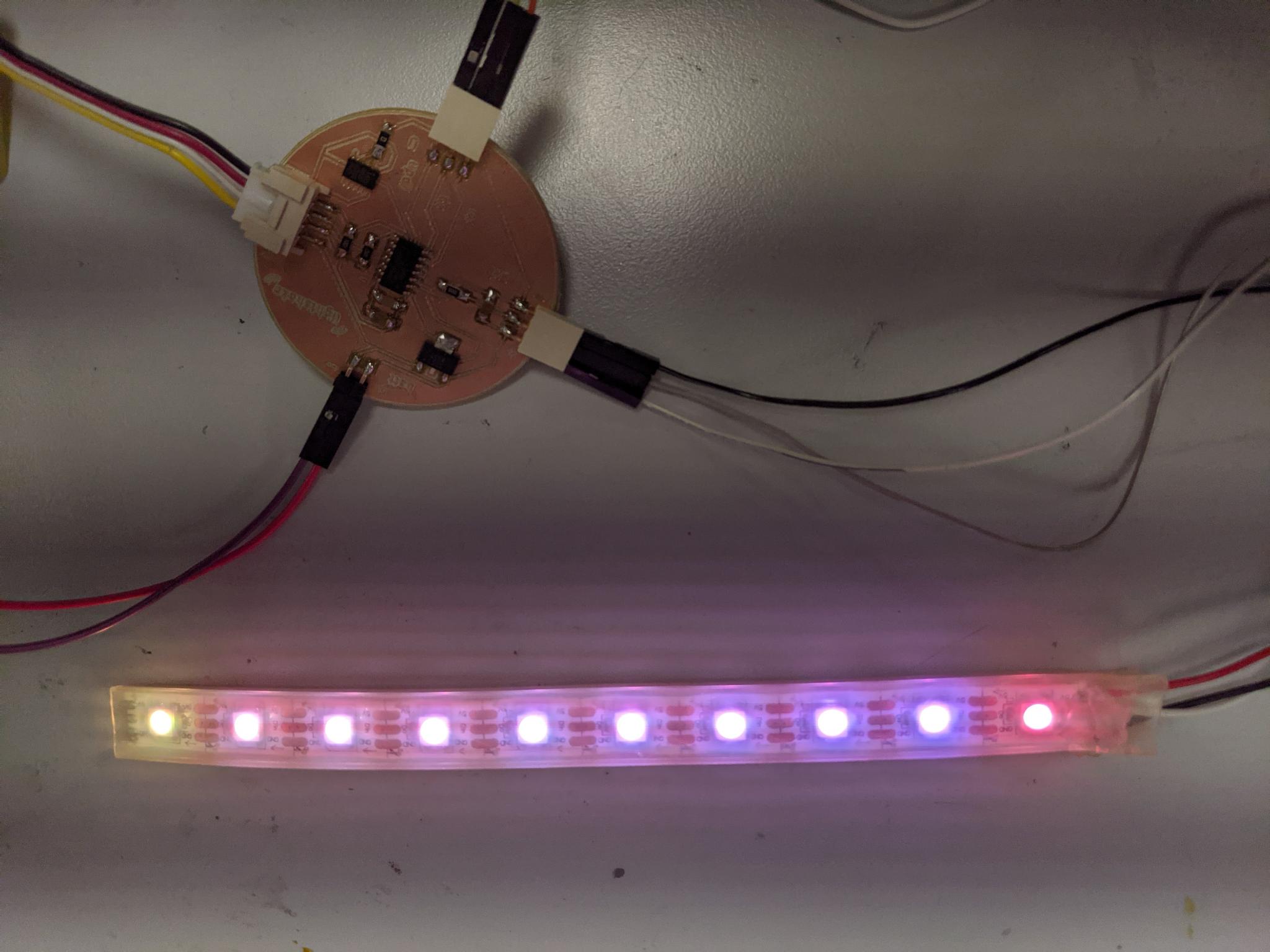
I achieved the simple action I wanted to: blend the colors of each tip of the led strip when I shake the accelerometer. Ultimately I will have all components attach together so the movement of the led tube will create that interaction.
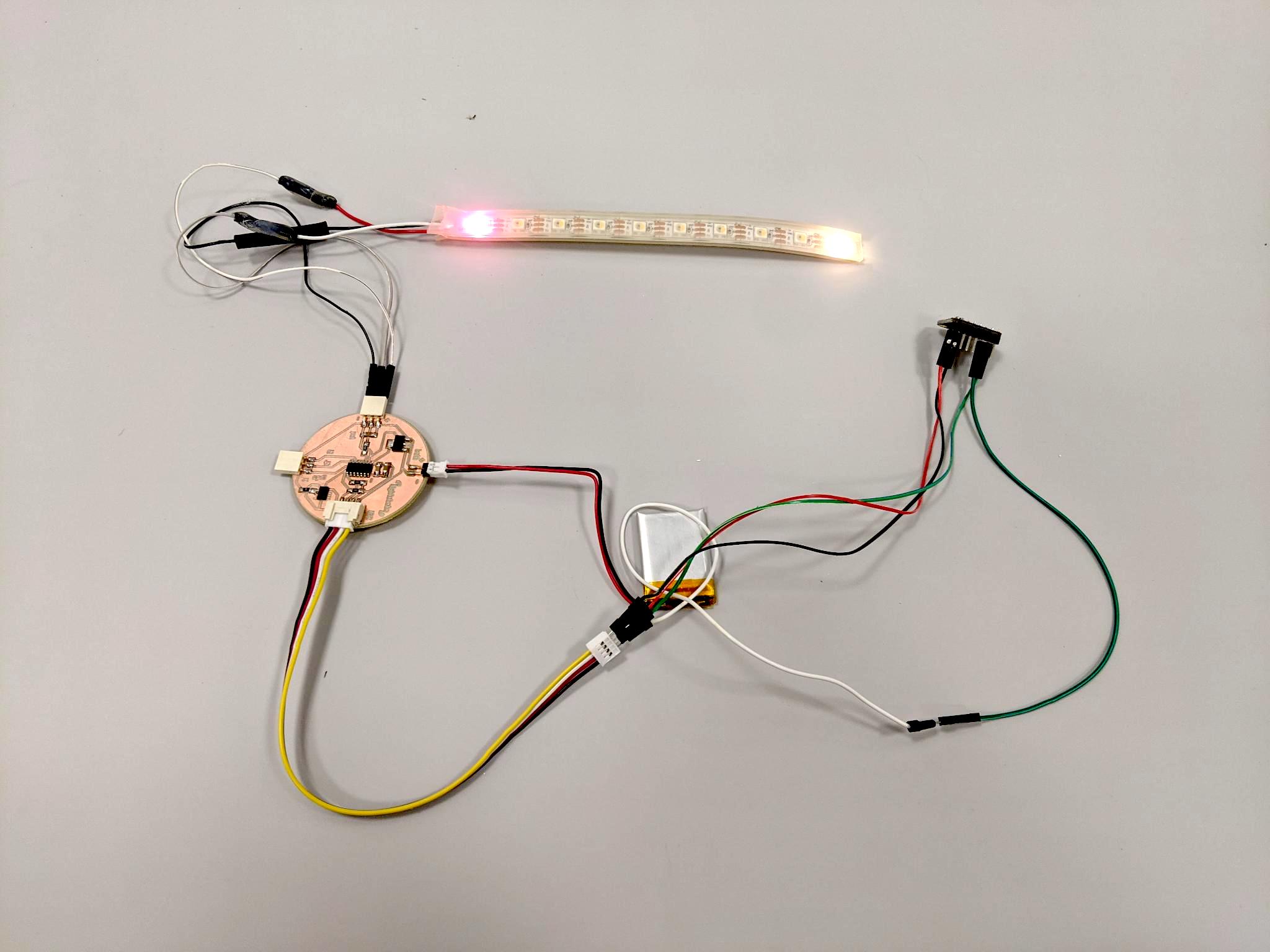
Circuit before shaking:
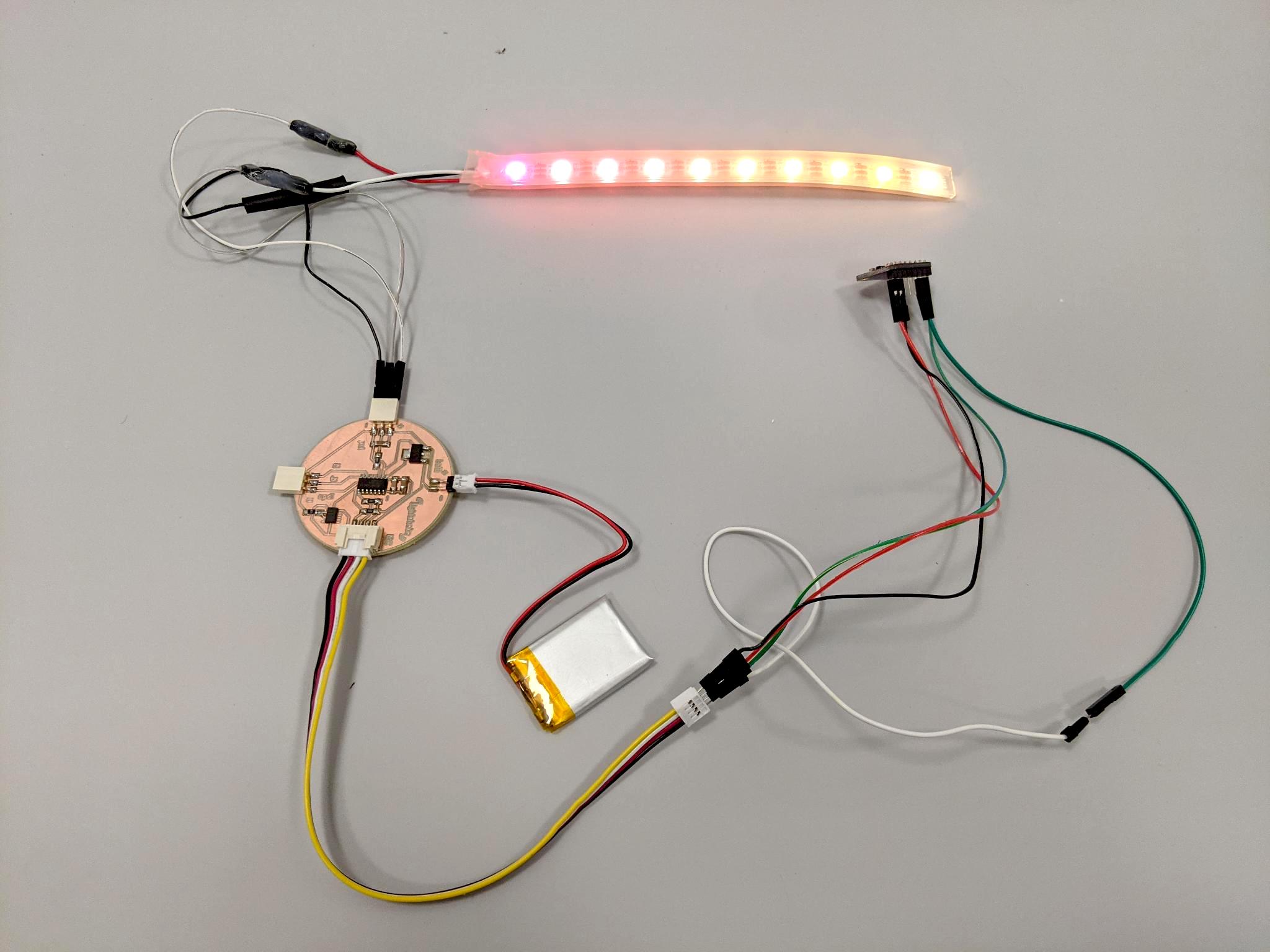
Circuit after shaking movement:
Yet another board!
In order to place the MMA8451 accelerometer directly on the circuit I redesigned my board. I also removed the ADXL343, and changed the grove for header pins. I changed the regulator for a smaller one (3.3 V 100mA and with smaller footprint).
I hand soldered it. Not working yet, stay tuned 8-)