Week 08 - Group assignment
The goal is to characterize some limits of our milling machine / mills
Prepare path in mods
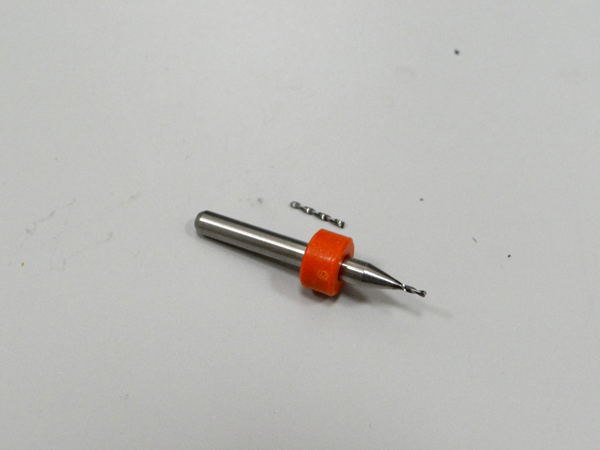
We'll use the traces test provided by the fabacademy to evaluate the limits of a cylindric 0.4mm mill.
The png files of the PCB can be found on the fabacademy website:
Here's how to mill a PCB from mods on a Roland SRM20, using png files.
- First open the web interface of mods mods.cba.mit.edu
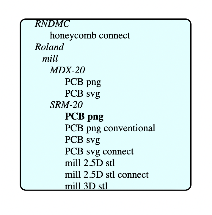
- Right-click anywhere on the white space to add a block: we'll start with
programs -> open server program -> Roland > mill > SRM-20 > PCB png. A network of boxes appears on the canvas.
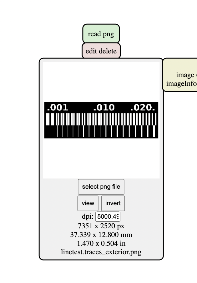
- We can now import the traces file by clicking on
select png filein the first block on the top left
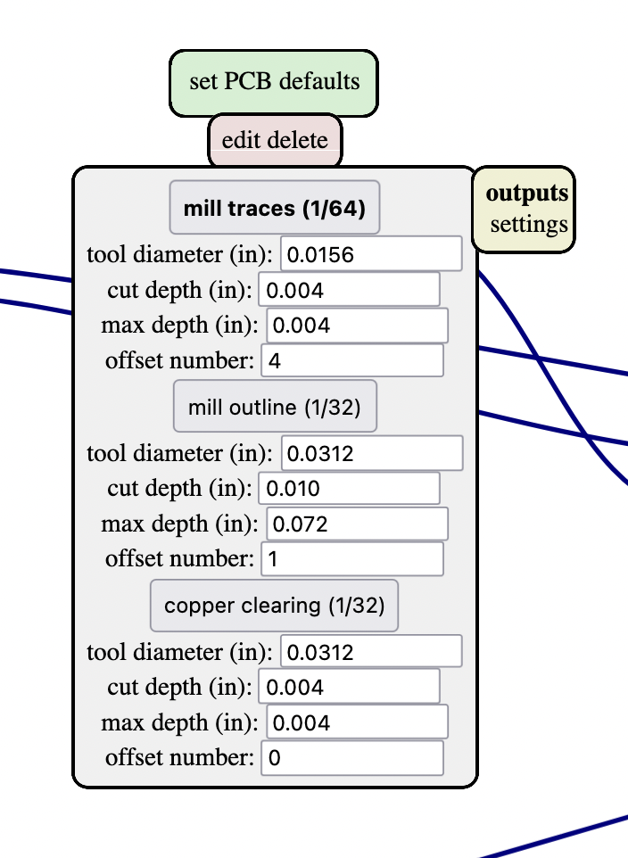
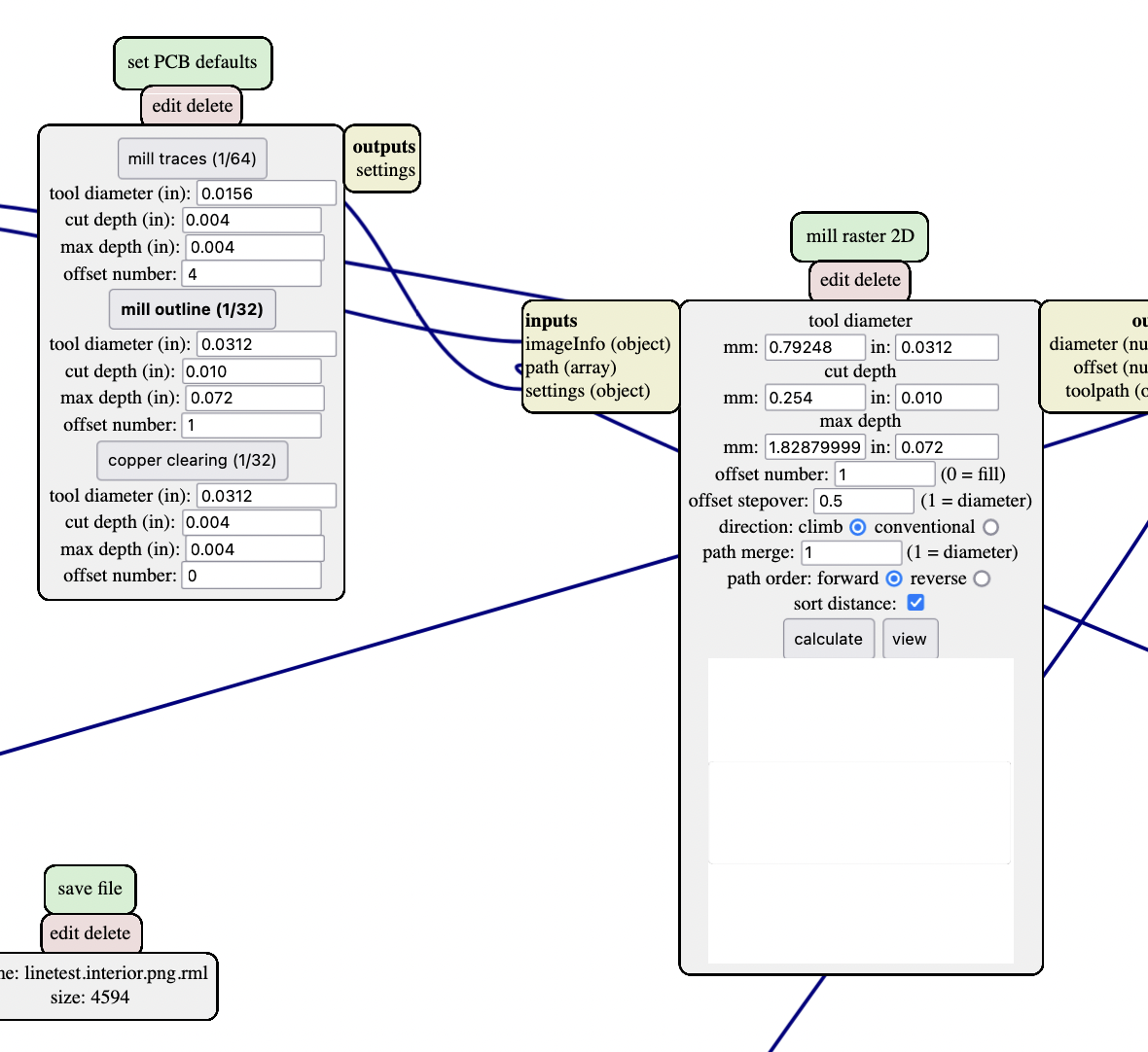
- To set the mill parameters, we can directly enter them in the
mill raster 2Dblock, or chose one of the presets in theset PCB defaultsbox. For the traces we can click on the buttonmill traces 1/64, which will change the value in themill raster 2Dblock.
- We'll need to save our files locally, then upload them on the Roland SRM-20 computer through its dedicated interface. In order to do this we can delete the
Web socketblock and replace it by asave fileblock. To do so, first click on delete in theWeb socketblock, then right click on the blank space and create a module:modules -> open server module -> file > save
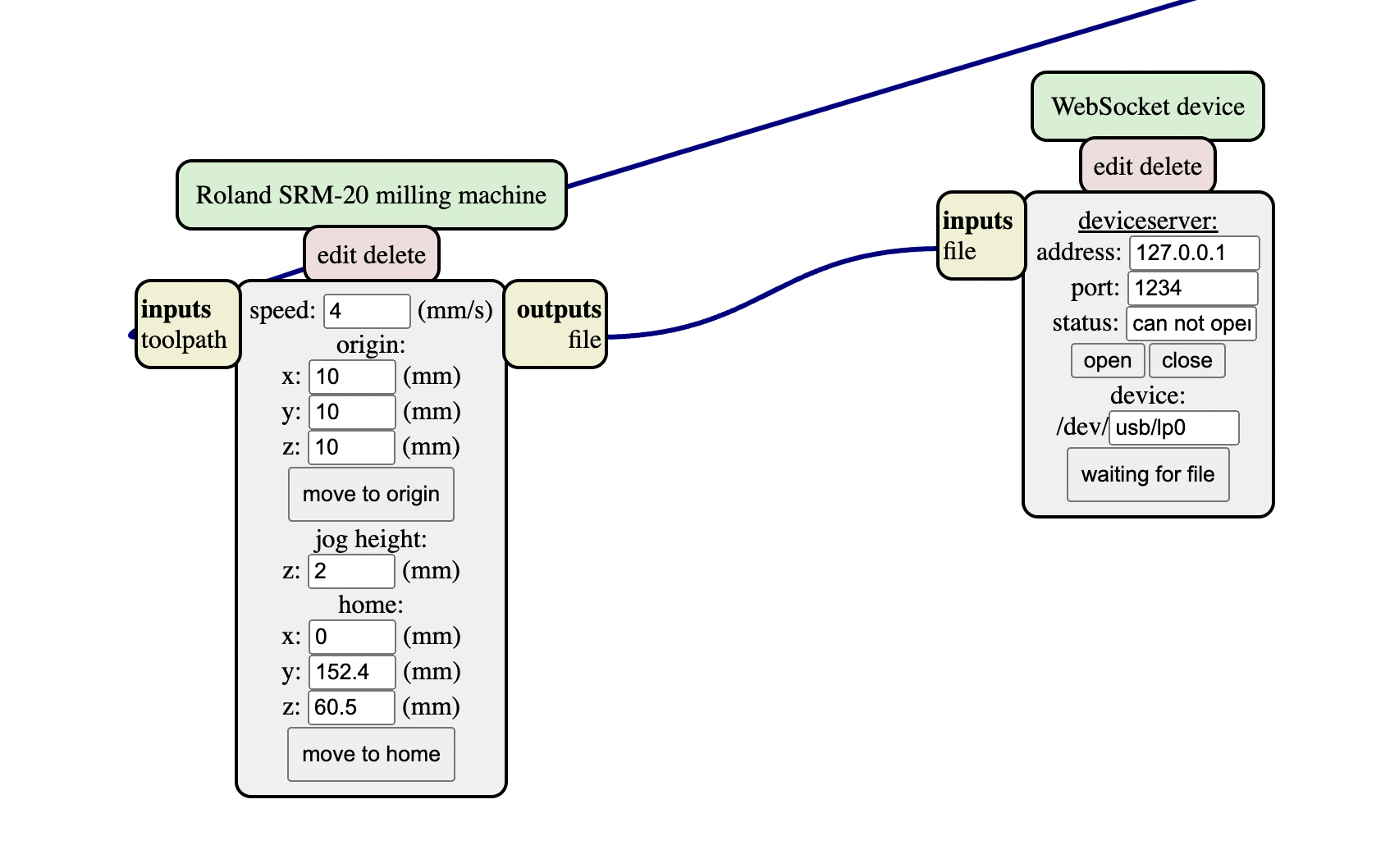
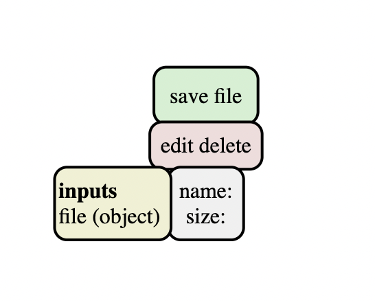
- Link the
save fileblock to theRoland SRM-20 milling machineblock: click on the yellow boxoutputs fileon the right of the Roland box, then on theinputs fileyellow box on the left of thesave fileblock
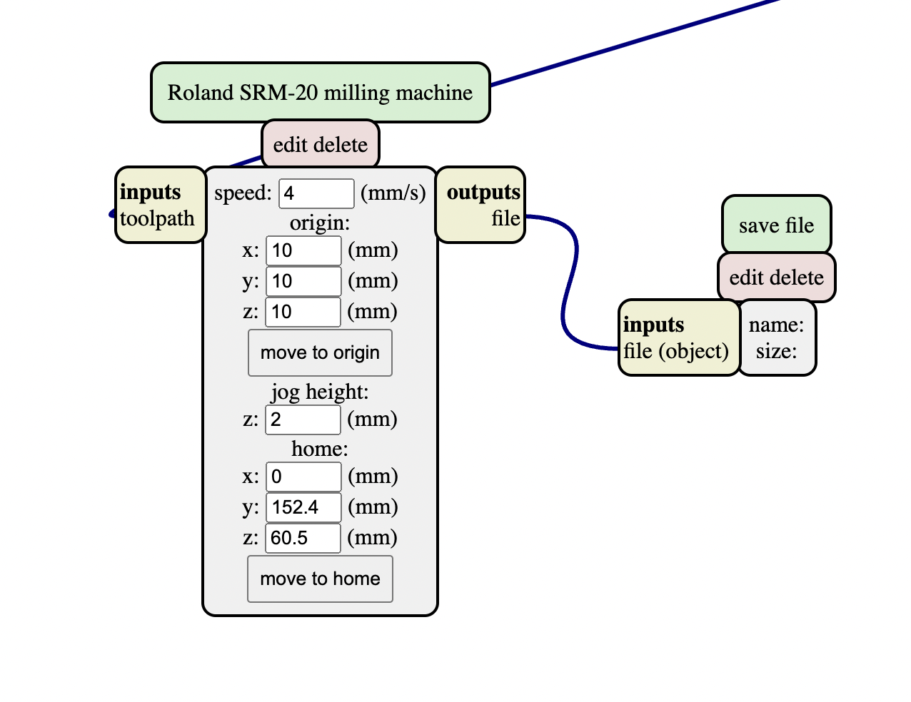
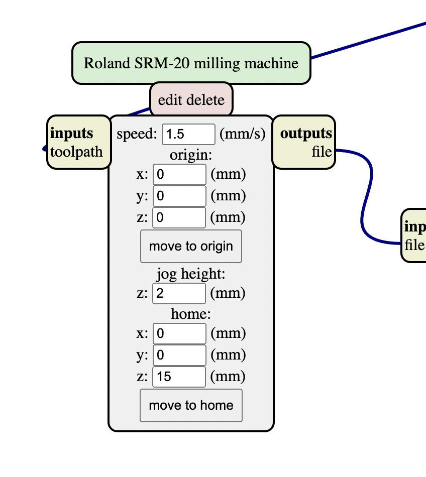
- We have some parameters to change in the
Roland SRM-20 milling machineblock: the speed, and the home and origin coordinates. It's very important to set a z home above 0, like 15mm, to avoid hitting anything and breaking the mill:
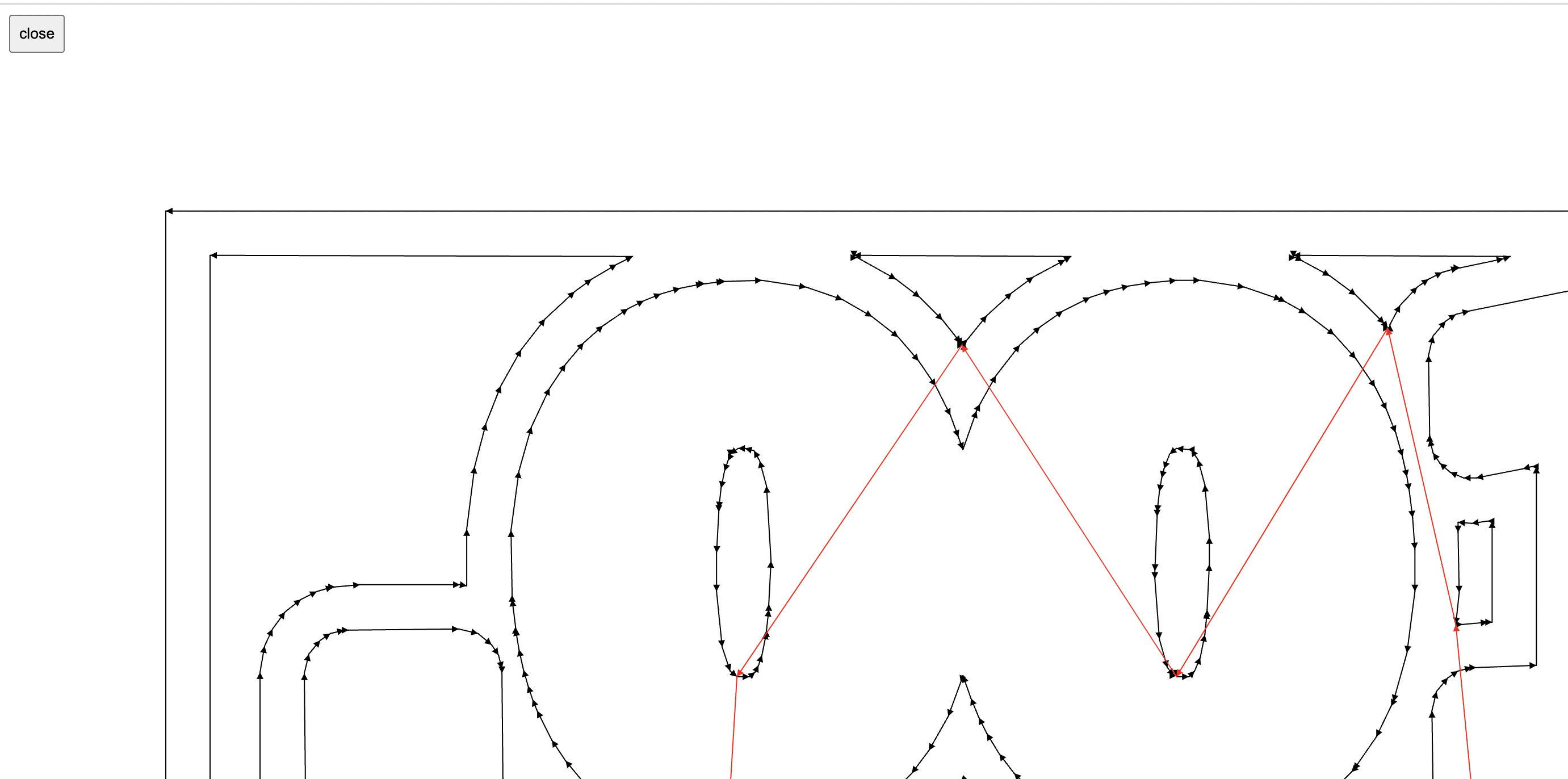
- Let's check the mill parameters, then click on calculate. A preview appears in the block.
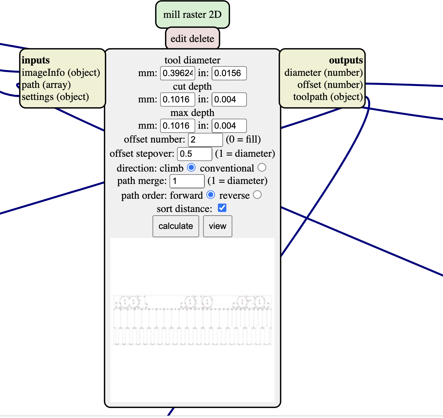
- We can open the preview in a new window by clicking on View. The generated path is automatically saved in
.rmlformat (you should find it in your Downloads folder)
-
We're now ready to mill the rml file with a 0.4mm mill. Let's generate the edge cut path before carrying on with the proper milling.
-
Import the edge cut png file (the same way you did for the traces png).
-
Change the mill parameters. I used the preset
mill outline (1/32)
I had issues when milling at that point (see below).
Milling
-
Turn on the Roland SRM-20 machine and open the interface from the computer.
-
In order to open and read correctly
.rmlfiles, you need to specify it in the interface preferences by clicking onSetup: select the radio buttonRML-1(not the buttonNC / RML-1!!). You'll see that the coordinates menu is a bit different, you have no access anymore toG54coordinates for example, instead you'll use theUser interface coordinates. -
Prepare your 0.4mm mill and zero it as usual (see individual page). Do the XY origin too.
-
Click in
Cut, delete the previous files and add the.rmlfile corresponding to your traces. -
Do the same for the 0.8mm mill, with the edge cut rml file... or not?? I broke the mill, so ended using a 2mm mill (that we use normally) with the same rml file. I'm really puzzled with how mods works (compared to FlatCAM), as the settings we use don't appear as clearly as in FlatCAM in my opinion.
Results
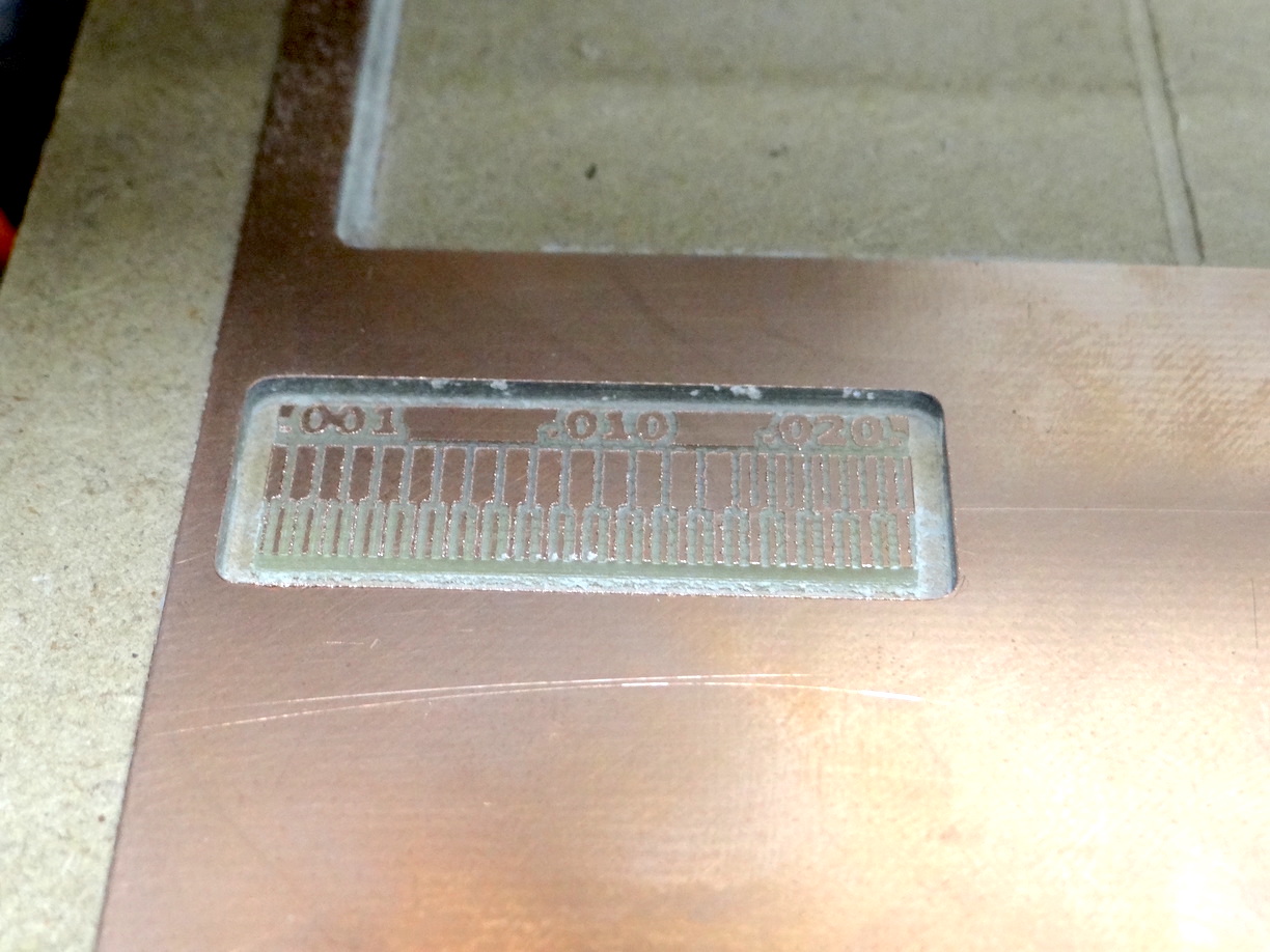
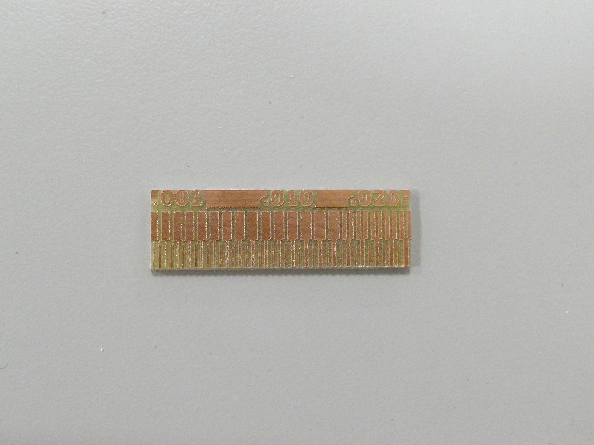
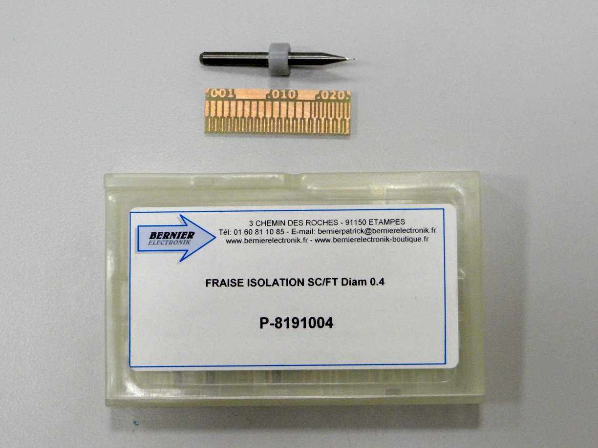
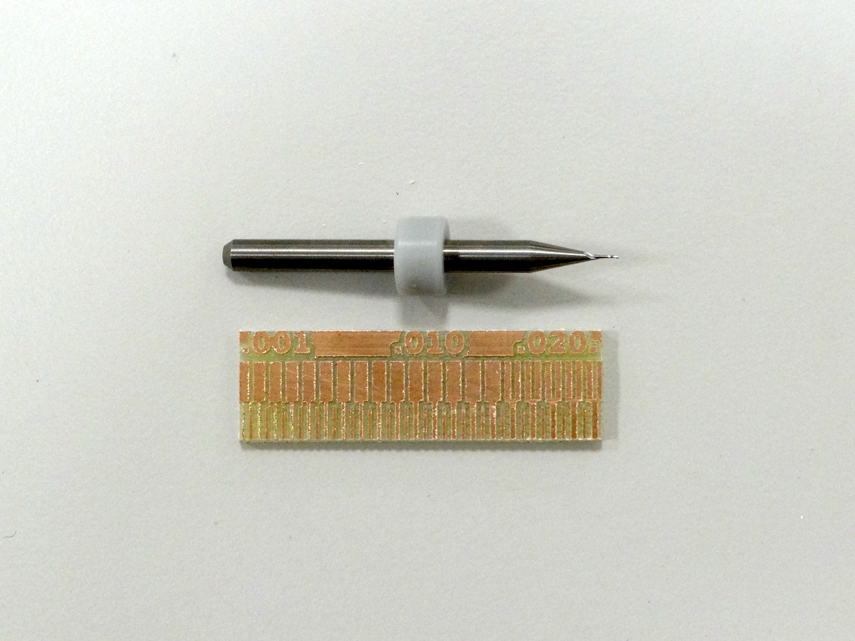
We can see that it was able to isolate all the thin traces (even the thinner ones), but not to do very thin cuts (.016mm is the smaller detail that was properly milled).