Week 03 - Group assignment
What's kerf in laser cutting jobs?
When a laser cuts through a piece of material, the laser’s own width displaces a little extra material than what's specified in the original design. The amount of material that is burned away is known as the kerf in laser cutting. It thus influences how you should design your CAD files to take that difference in account.
The notion of kerf doesn't concern only the laser cutting machine, but any type of cutting machine. For example a saw kerf would be related to the width of the tool: a cut in a piece of wood has a more or less important thickness.
Concerning the water jet cutting machine, the waterjet also creates a significative kerf effect, as the jet is rather wide. But unlike on our laser cutting machine and software, the Omax software take that kerf in account and adapt the generated path to obtain the exact dimensions specified in the original design. It thus interprates if a shape is an external or internal shape (see more on week 15 - Wilcard week).
A first kerf plywood measure
Here are the manipulation and results of my comrade Lauriane to characterize the kerf for 3mm thick birch plywood:
Materials: Laser cutting machine Caliper Plywood plate, 3mm thickness
Measures:
Rectangle: 100.50 mm 10 Squares : 97.55mm Kerf: 0.268mm
Comparing the kerf for various materials
I don't believe its sufficient to estimate the kerf for one material, because I have the feeling that the cutting settings (mainly the laser's power and speed) have a significative influence on the kerf. Indeed I talked about such implications with people much more aware of optical science than me, and it seems that you have an Airy disk optical aberration on your focus point, which diameter is linked to the focal, the wavelength and if I understood correctly to the energy of the ray.
I also found some tables online that compared kerf for various materials (see this example)
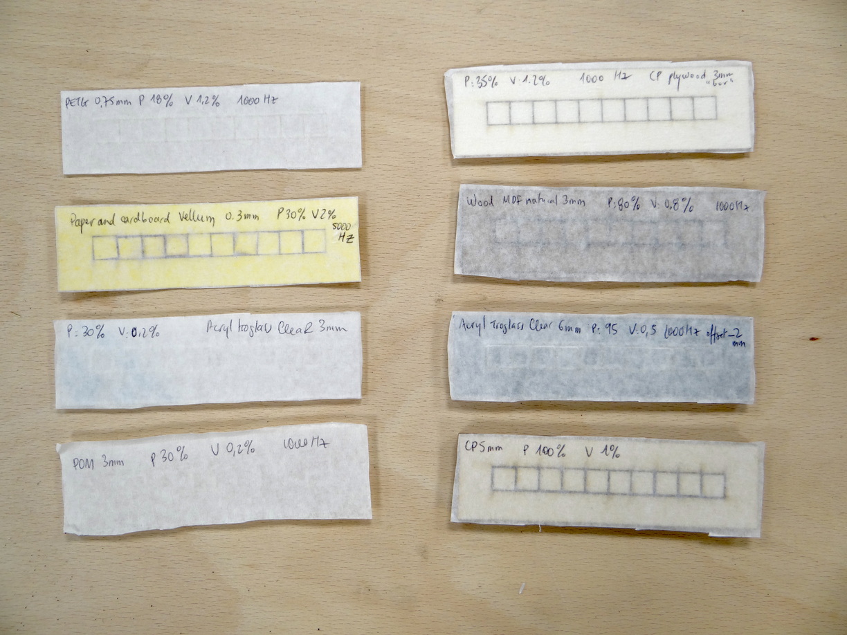
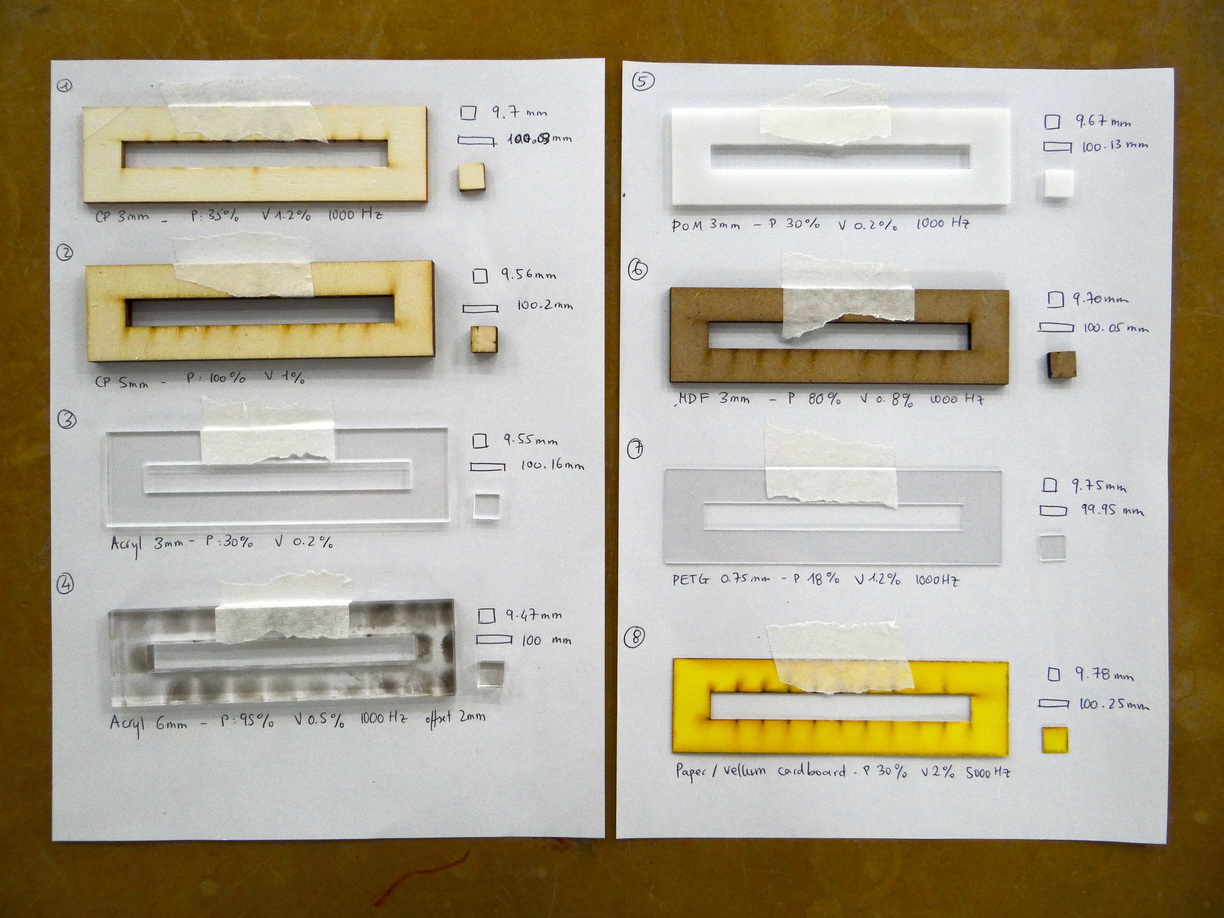
I thus decided to compare 8 various materials, also choosing various thicknesses, and thus using different cutting settings.
The lens focal distance also has an impact, but I did all my tests with a 2.5" focal lens and a long cone. Intituively I'd say that I would have smaller kerf values with a 1.5" lens but not sure at all about that.
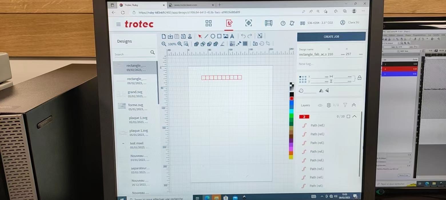
The design I cut was 10 squares of 10mm*10mm (not taking in account the outline thickness) carefully aligned. The first one is at X:0mm Y:0mm coordinates, the second one at X:10mm Y:0mm coordinates, the third one at X:20mm Y:0mm coordinates, etc.
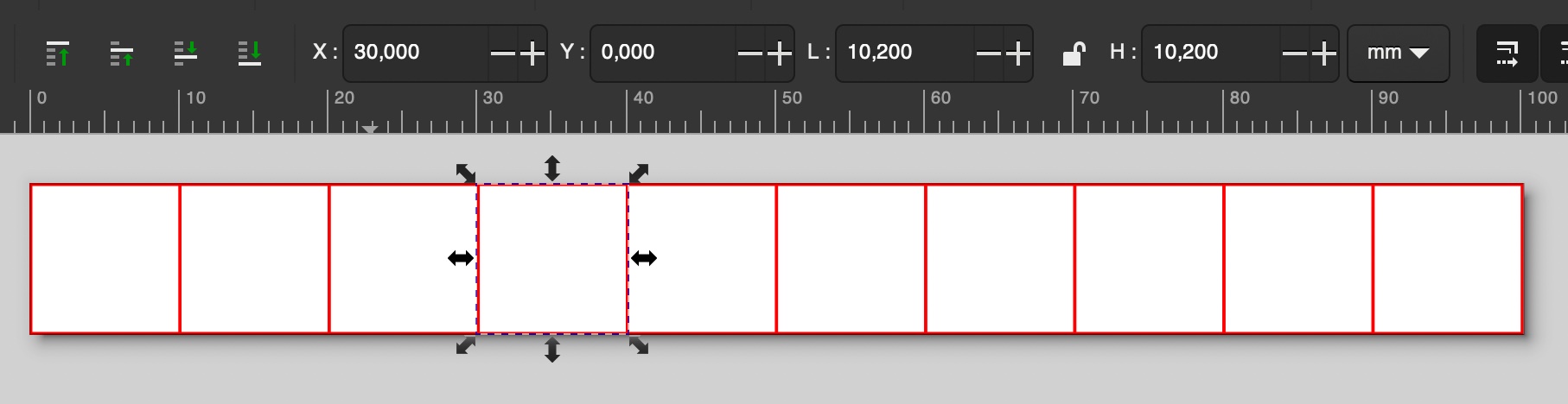
Here the indicated width and height of a square is 10.2mm because the stroke outline thickness is 0.2. To avoid being confused you can set these dimensions directly in the rectangle shape menu, where it doesn't take in account the stroke width
The svg file can be found here
Here are the materials I tested and the cutting settings I used:
| index | material description | power (%) | speed (%) | frequency (Hz) | offset (mm) |
|---|---|---|---|---|---|
| 1 | plywood 3mm | 35 | 1,2 | 1000 | 0 |
| 2 | plywood 5mm | 100 | 1 | 1000 | 0 |
| 3 | clear acrylic 3mm | 30 | 0,2 | 1000 | 0 |
| 4 | clear acrylic 6mm | 95 | 0,5 | 1000 | 2 |
| 5 | POM 3mm | 30 | 0,2 | 1000 | 0 |
| 6 | MDF 3mm | 80 | 0,8 | 1000 | 0 |
| 7 | PETG 0,75mm | 18 | 1,2 | 1000 | 0 |
| 8 | thin cardboard 0,3mm | 30 | 2 | 5000 | 0 |
Carefully writing settings down while cutting my pieces:
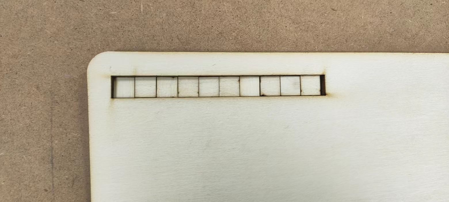
I used a caliper to measure the following lengths in the x-axis (the horizontal length) for each material:
L: length of the inner cut of the big rectangle (resulting from cutting off all squares) l: length of a side of a square (be carefull to measure along the x-axis, although in theory the sides have the same length, in practice they don't.)
Here are the measures for all the materials
| index | material description | l (mm) | L (mm) |
|---|---|---|---|
| 1 | plywood 3mm | 9,7 | 100,03 |
| 2 | plywood 5mm | 9,56 | 100,2 |
| 3 | clear acrylic 3mm | 9,55 | 100,16 |
| 4 | clear acrylic 6mm | 9,47 | 100 |
| 5 | POM 3mm | 9,67 | 100,13 |
| 6 | MDF 3mm | 9,7 | 100,05 |
| 7 | PETG 0,75mm | 9,75 | 99,95 |
| 8 | thin cardboard 0,3mm | 9,78 | 100,25 |
So how to calculate the kerf now? I made a little schematic to visualize my different measures. L0 and l0 are the theoretical values corresponding to L and l, e.g. L0=100mm and l0=10mm.
If I'm correct the kerf is the width of the extra material removed by the laser beam. I noted it 'k' in my schematic.
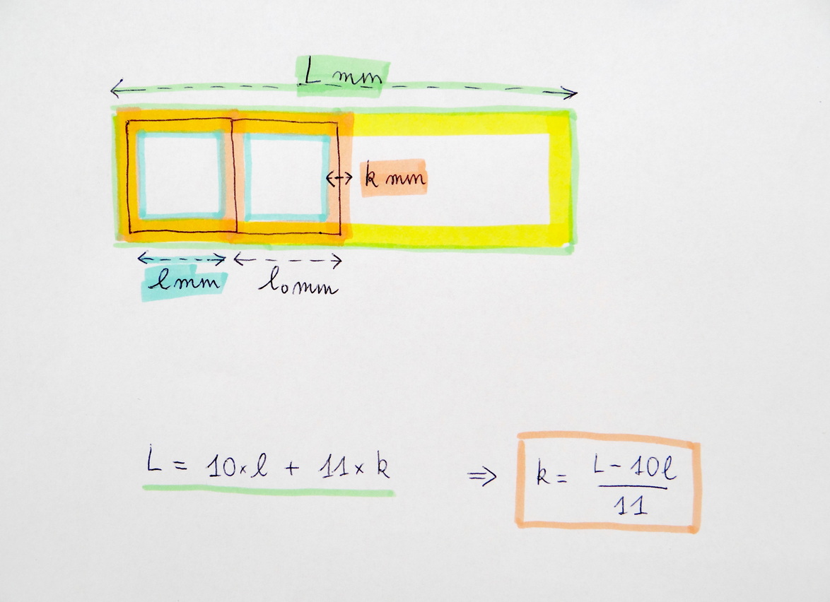
A way to calculate k using my measures L and l thus seems to be:
L = 10 * l + 11 * k => k = (L - 10 * l) / 11
Which gives us the following estimations:
| index | material description | l (mm) | L (mm) | k (mm) |
|---|---|---|---|---|
| 1 | plywood 3mm | 9,7 | 100,03 | 0,27545455 |
| 2 | plywood 5mm | 9,56 | 100,2 | 0,41818182 |
| 3 | clear acrylic 3mm | 9,55 | 100,16 | 0,42363636 |
| 4 | clear acrylic 6mm | 9,47 | 100 | 0,48181818 |
| 5 | POM 3mm | 9,67 | 100,13 | 0,31181818 |
| 6 | MDF 3mm | 9,7 | 100,05 | 0,27727273 |
| 7 | PETG 0,75mm | 9,75 | 99,95 | 0,22272727 |
| 8 | thin cardboard 0,3mm | 9,78 | 100,25 | 0,22272727 |
Another way, more straightforward, seems to simply substract l to l0, but probably less accurate. Let's note k' this second approximation. k' = l0 - l, where l0=10mm.
Here is the sum up with the values of k as calculated before, and this new approximation k':
| index | material description | k (mm) | k' (mm) |
|---|---|---|---|
| 1 | plywood 3mm | 0,27545455 | 0,3 |
| 2 | plywood 5mm | 0,41818182 | 0,44 |
| 3 | clear acrylic 3mm | 0,42363636 | 0,45 |
| 4 | clear acrylic 6mm | 0,48181818 | 0,53 |
| 5 | POM 3mm | 0,31181818 | 0,33 |
| 6 | MDF 3mm | 0,27727273 | 0,3 |
| 7 | PETG 0,75mm | 0,22272727 | 0,25 |
| 8 | thin cardboard 0,3mm | 0,22272727 | 0,22 |
I'll stick with the approximation k, because it feels natural to think that the errors are attenuated by the use of 10 squares instead of 1. So here is the summary when I include the lasercutting power and speed:
| index | material description | power (%) | speed (%) | l (mm) | L (mm) | estimated kerf (mm) |
|---|---|---|---|---|---|---|
| 1 | plywood 3mm | 35 | 1,2 | 9,7 | 100,03 | 0,27545455 |
| 2 | plywood 5mm | 100 | 1 | 9,56 | 100,2 | 0,41818182 |
| 3 | clear acrylic 3mm | 30 | 0,2 | 9,55 | 100,16 | 0,42363636 |
| 4 | clear acrylic 6mm | 95 | 0,5 | 9,47 | 100 | 0,48181818 |
| 5 | POM 3mm | 30 | 0,2 | 9,67 | 100,13 | 0,31181818 |
| 6 | MDF 3mm | 80 | 0,8 | 9,7 | 100,05 | 0,27727273 |
| 7 | PETG 0,75mm | 18 | 1,2 | 9,75 | 99,95 | 0,22272727 |
| 8 | thin cardboard 0,3mm | 30 | 2 | 9,78 | 100,25 | 0,22272727 |
We can make some rough observations:
- There seems to be a global tendency indicating that the 'stronger' the cutting settings (high power and low speed), the larger the measured kerf.
- For a same type of material, the kerf varies significatively between different thicknesses (implying different power / speed settings). Indeed, the estimated kerf is 0,275mm for 3mm thick plywood (birch) and 0,418mm for 5mm thick plywood (birch also). Similarly, the kerf is bigger for the 6mm thick acrylic than for the 3mm thick one.
- For identical power and speed settings, it seems the kerf may vary depending on the material itself, maybe the way they react to the laser beam. Thus we've calculated different kerfs for clear acrylic 3mm (kerf of 0,423mm) and for POM 3mm (kerf of 0,312mm), even if they were cut using the same settings (power 30% speed 0,2%).
- The PETG L measure is smaller than the theoretical one (99,95mm < 100mm), which could be due to some error measures, but maybe also to effects happening after the cut, such as melting and solidifying in a deformed way.
- My comrade Lauriane didn't write down the cutting settings used for her measurement of the 3mm thick birch plywood but they're probablu similar to those I used. Anyway, the estimation she obtained (0.268mm) and mine (0.275mm) are relatively close (difference of 0.007mm, corresponding to 2.5% of my estimation).