Logbook
An ultimate spiralling achievement, an exciting and sometimes overwhelming exploration
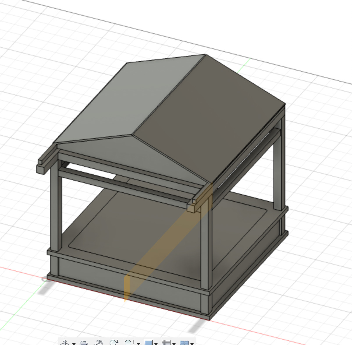
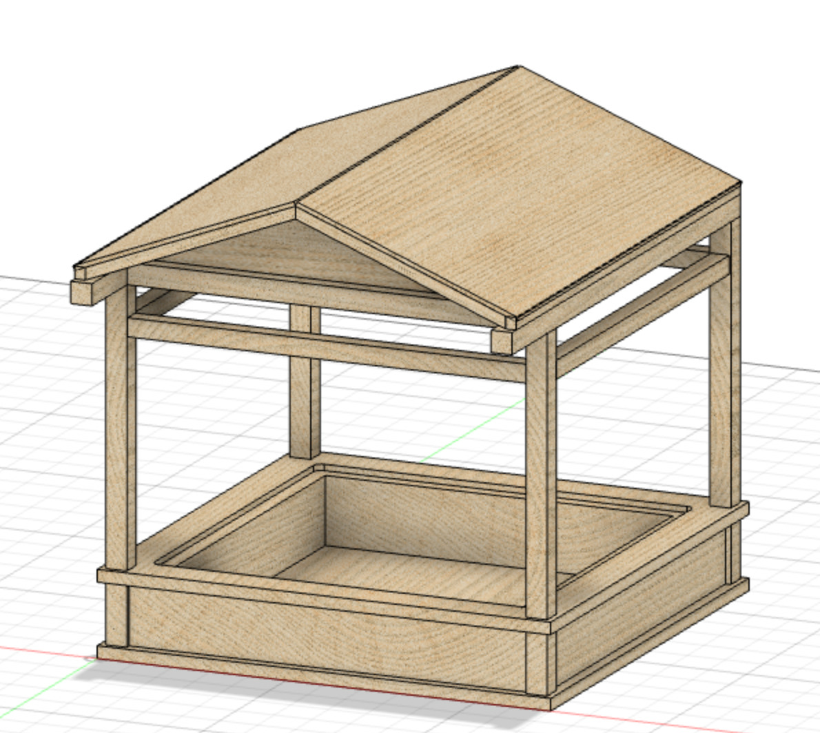
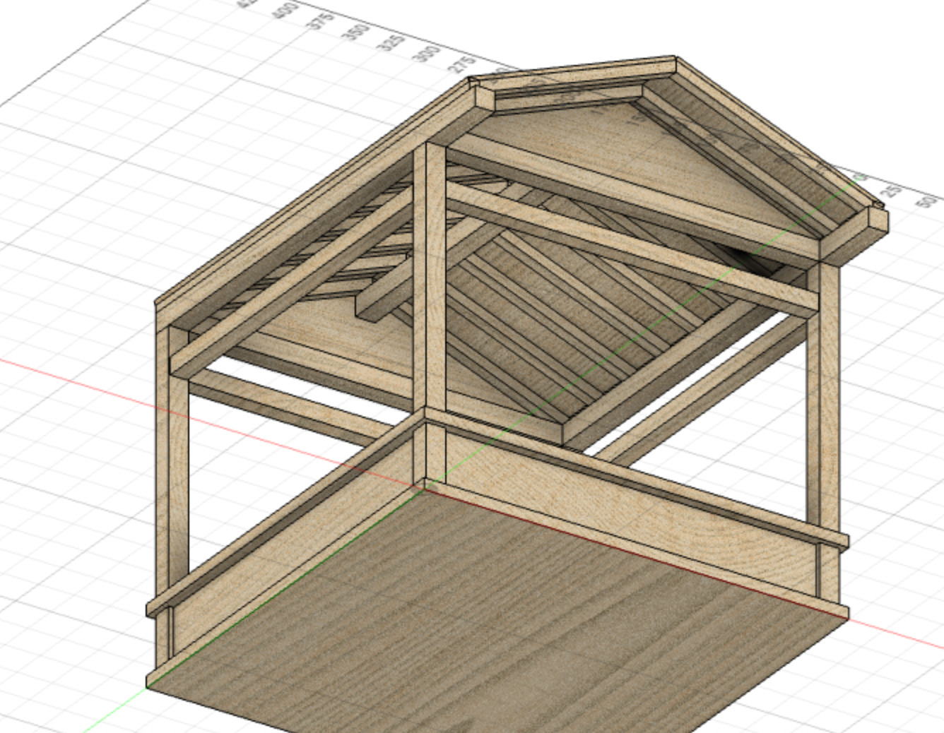
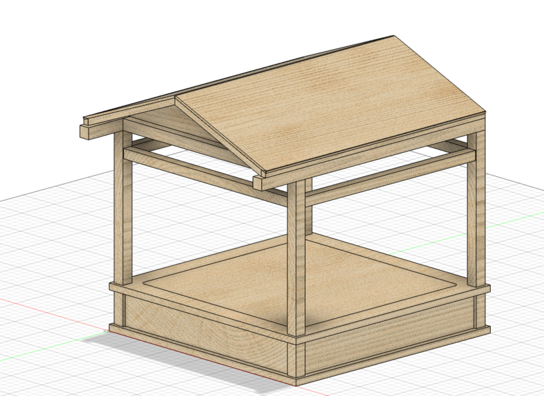
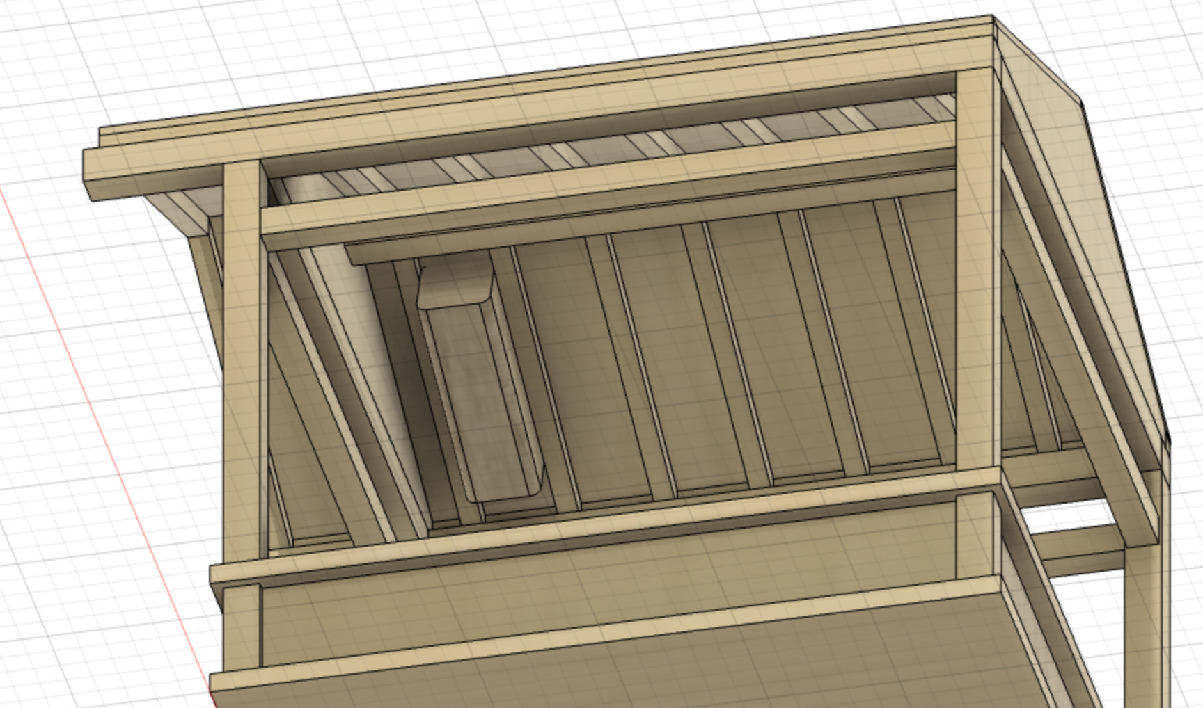
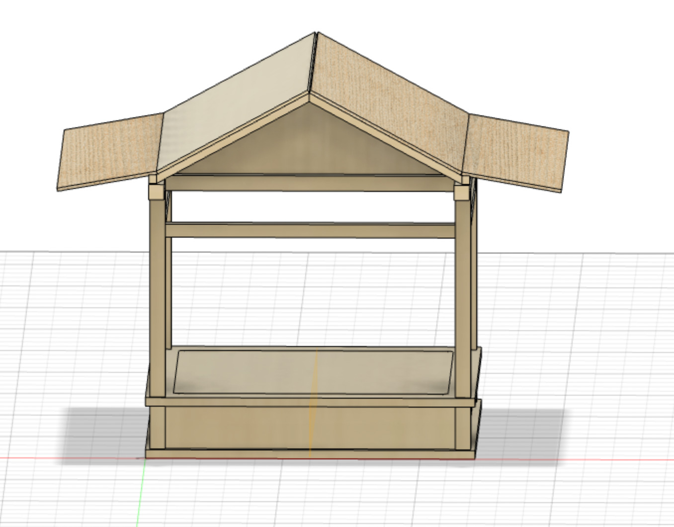
General overview illustrations
I would like to create a tool to experiment light art. My intention with this project is to provide a small set of tools to explore light in an esthetic way.
Initial thoughts sketches
Elements that could be provided, sketch from Week 1
An example of process to set the color of the led elements, sketch from Week 1
RFID tests
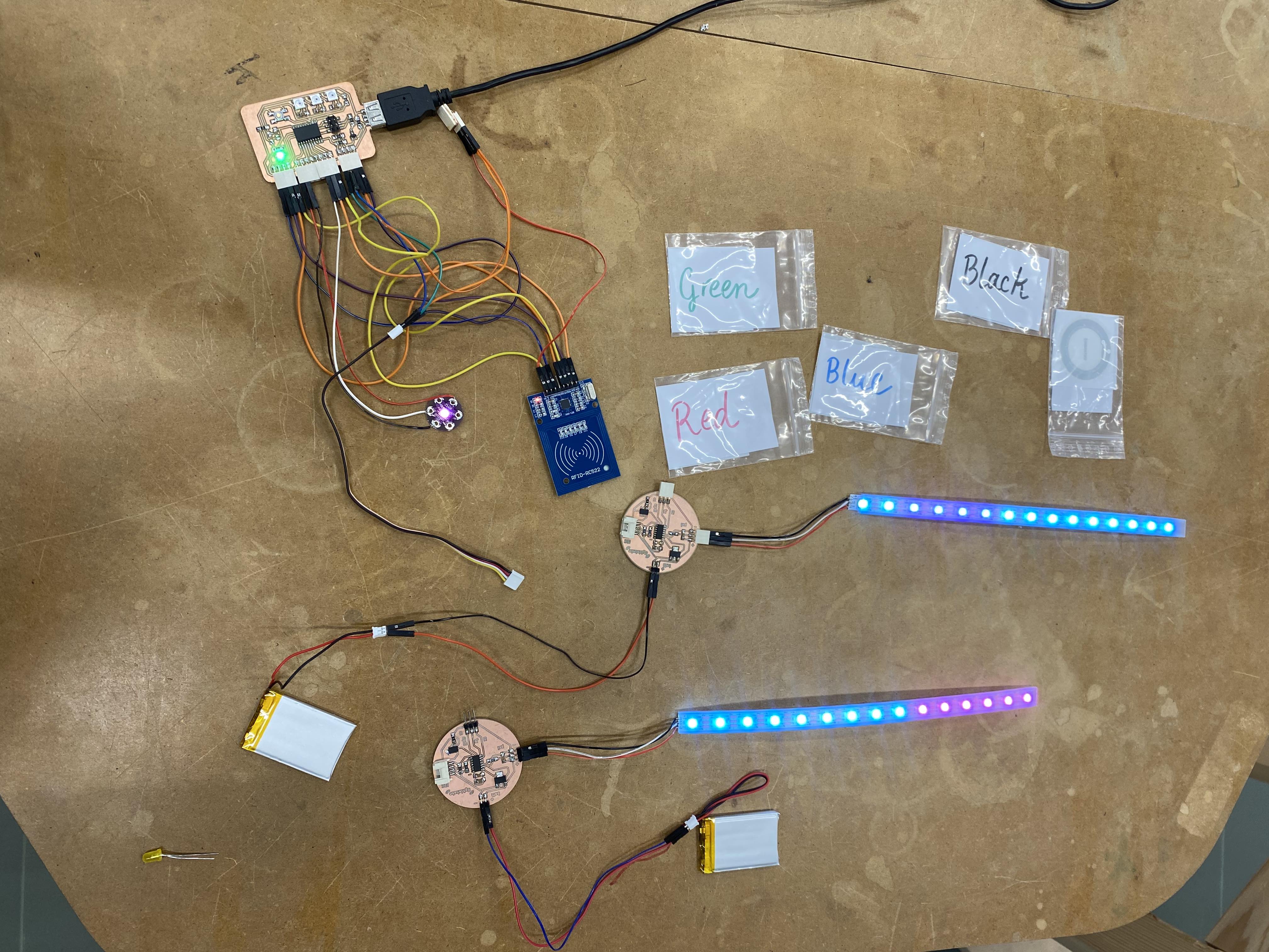
RFID tests done during Week 3 - Embedded programming
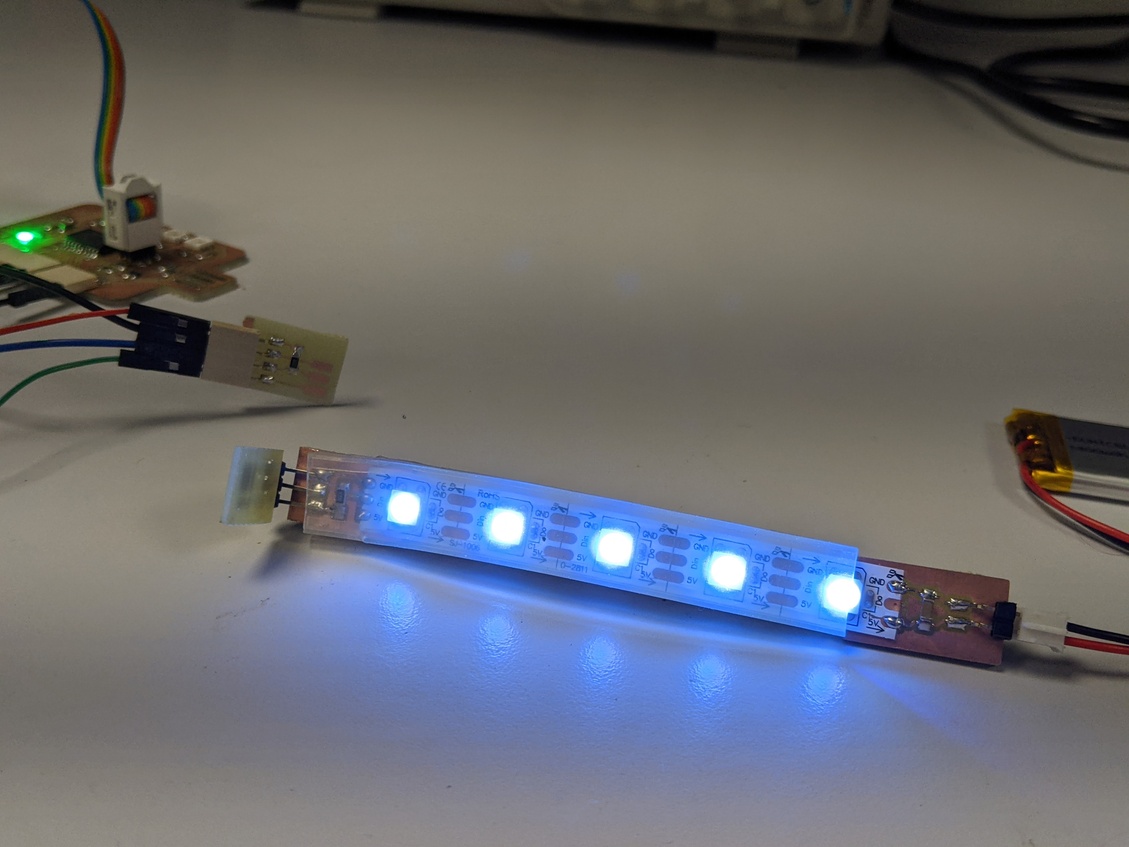
Lighting tests
Lighting tests done during Week 9 - Output devices
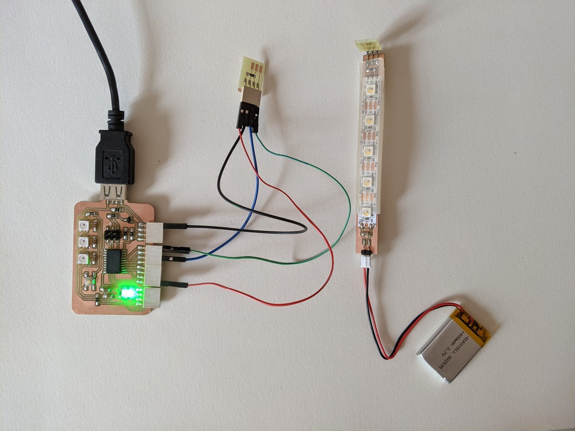
Reducing the number of power supplies and microcontrollers
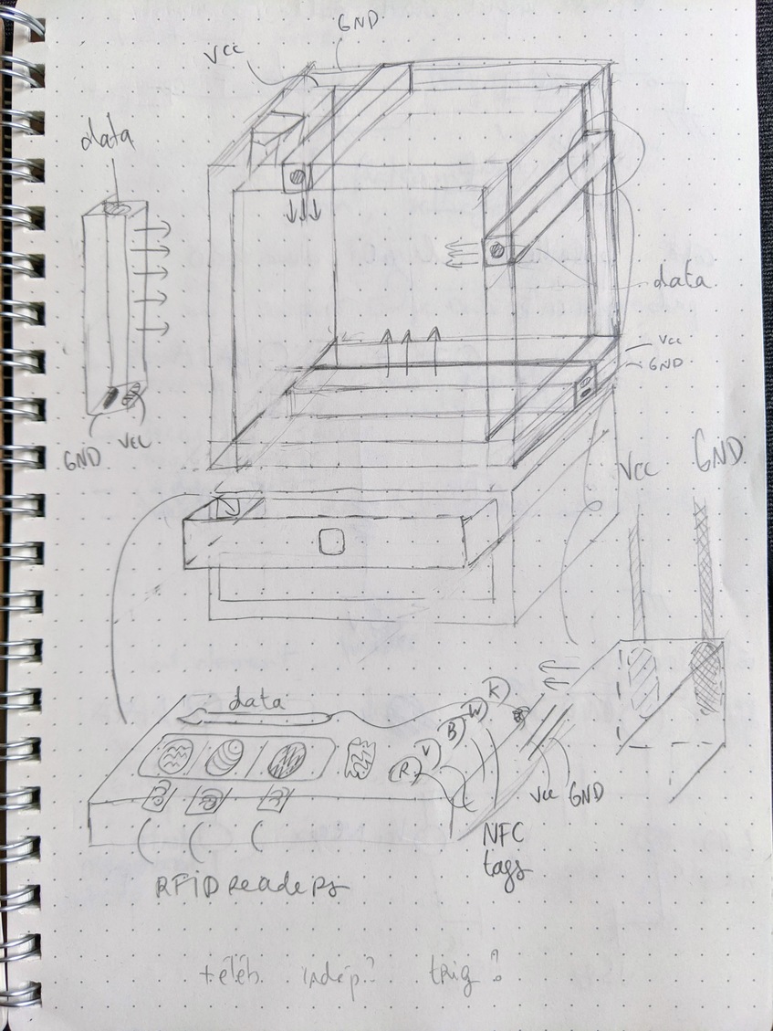
Experimenting independent led elements with no microcontrollers during Week 9 - Output devices
Gyroscopic RGB pallette
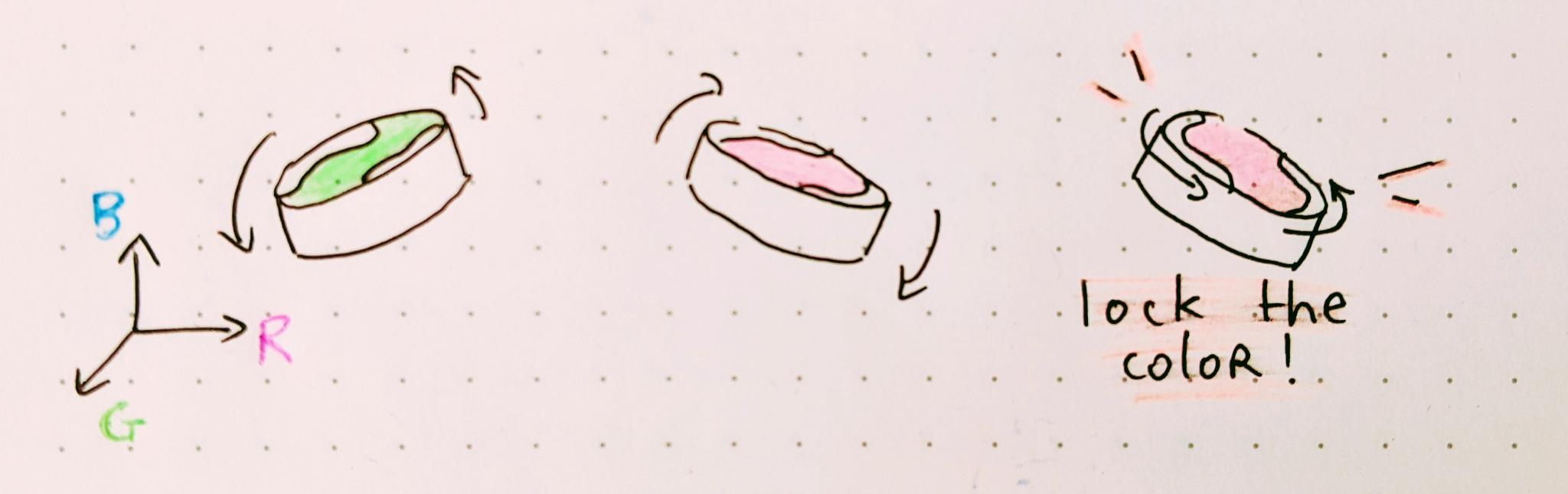
Another idea to change the colors of the palette
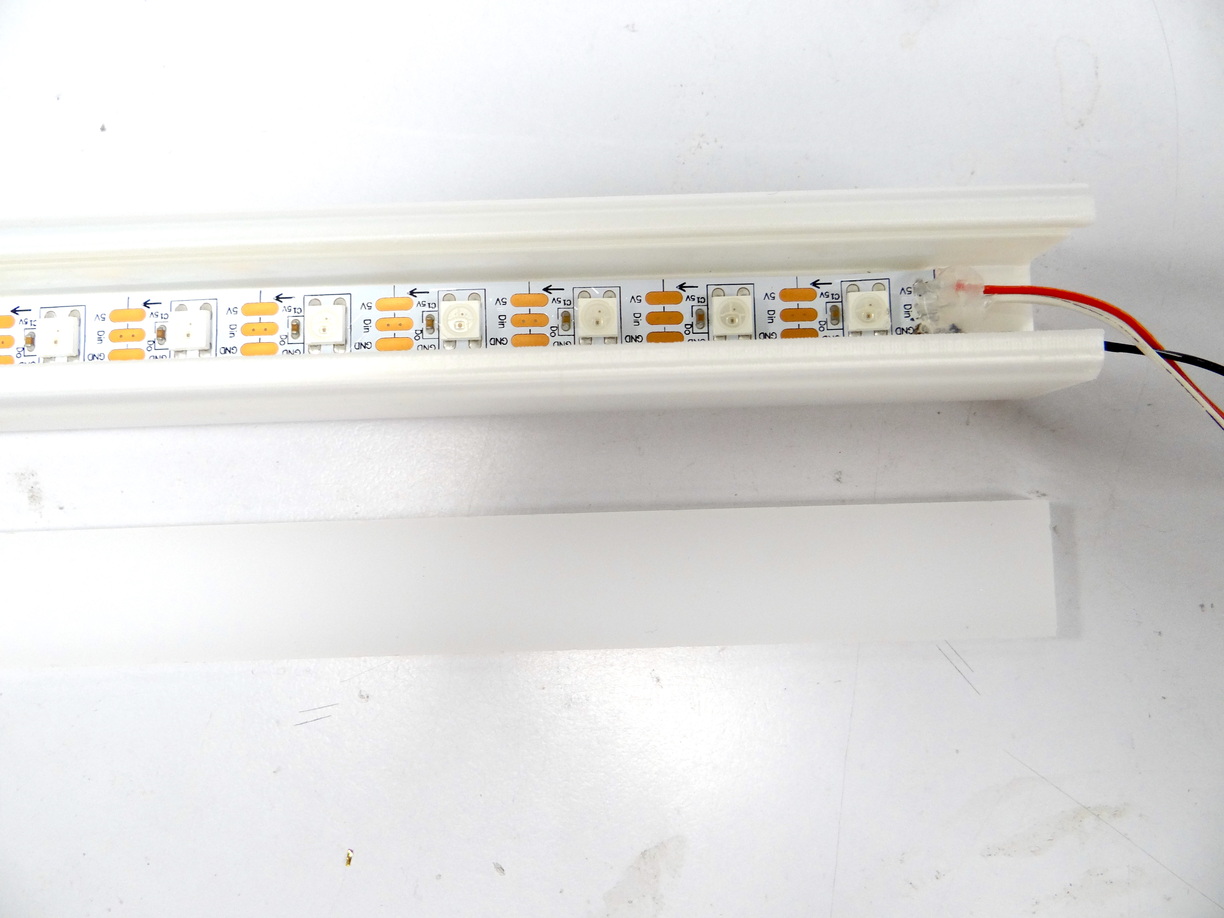
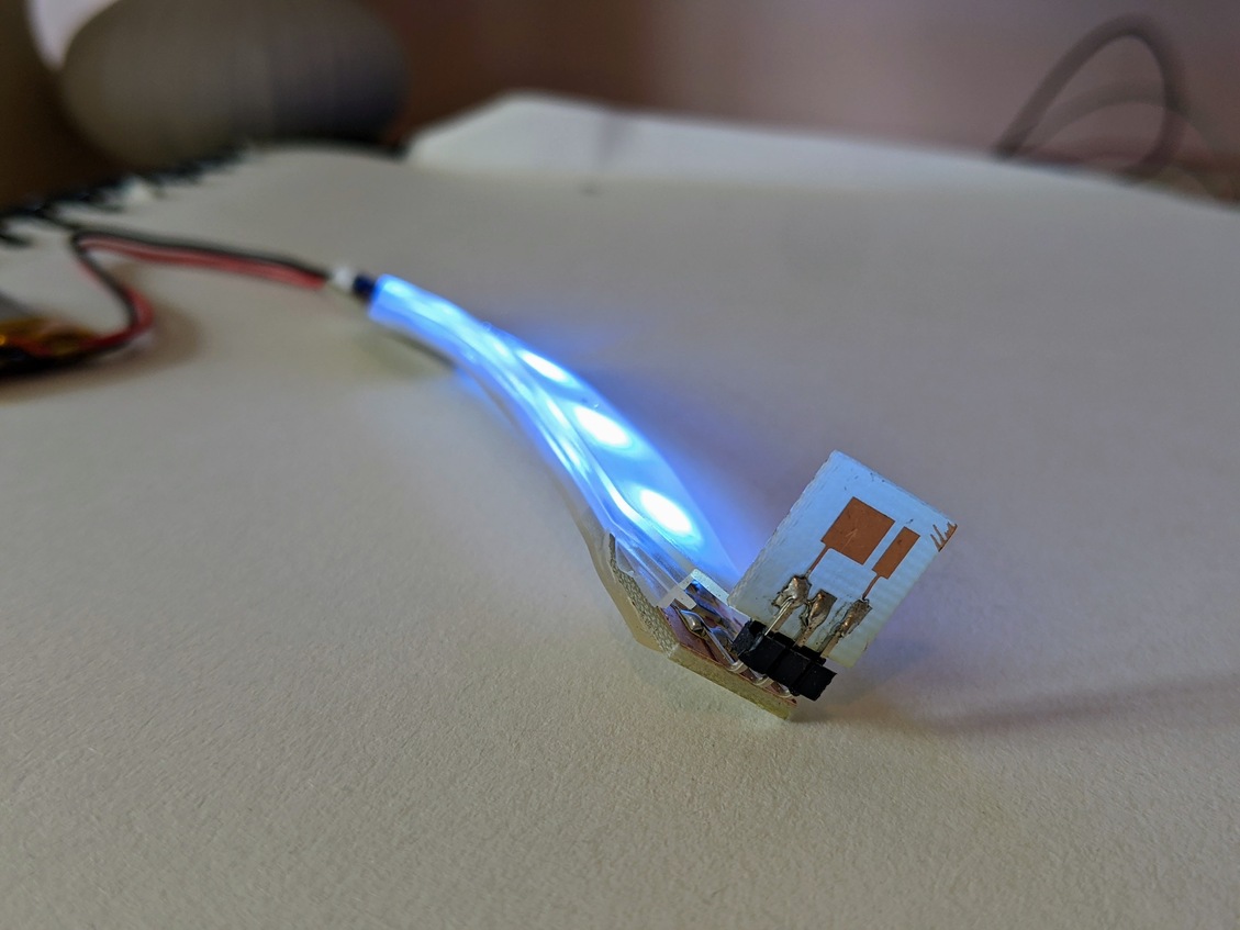
Lightshake led element
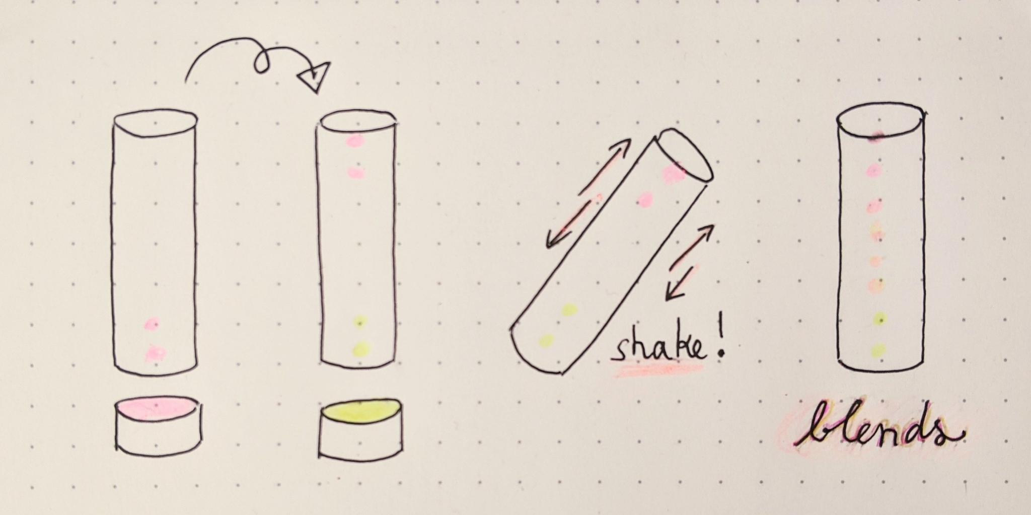
The process to fill the led element and create a color gradient with a shaking gesture
The coding and demo of that effect made during Week 11 - Input devices
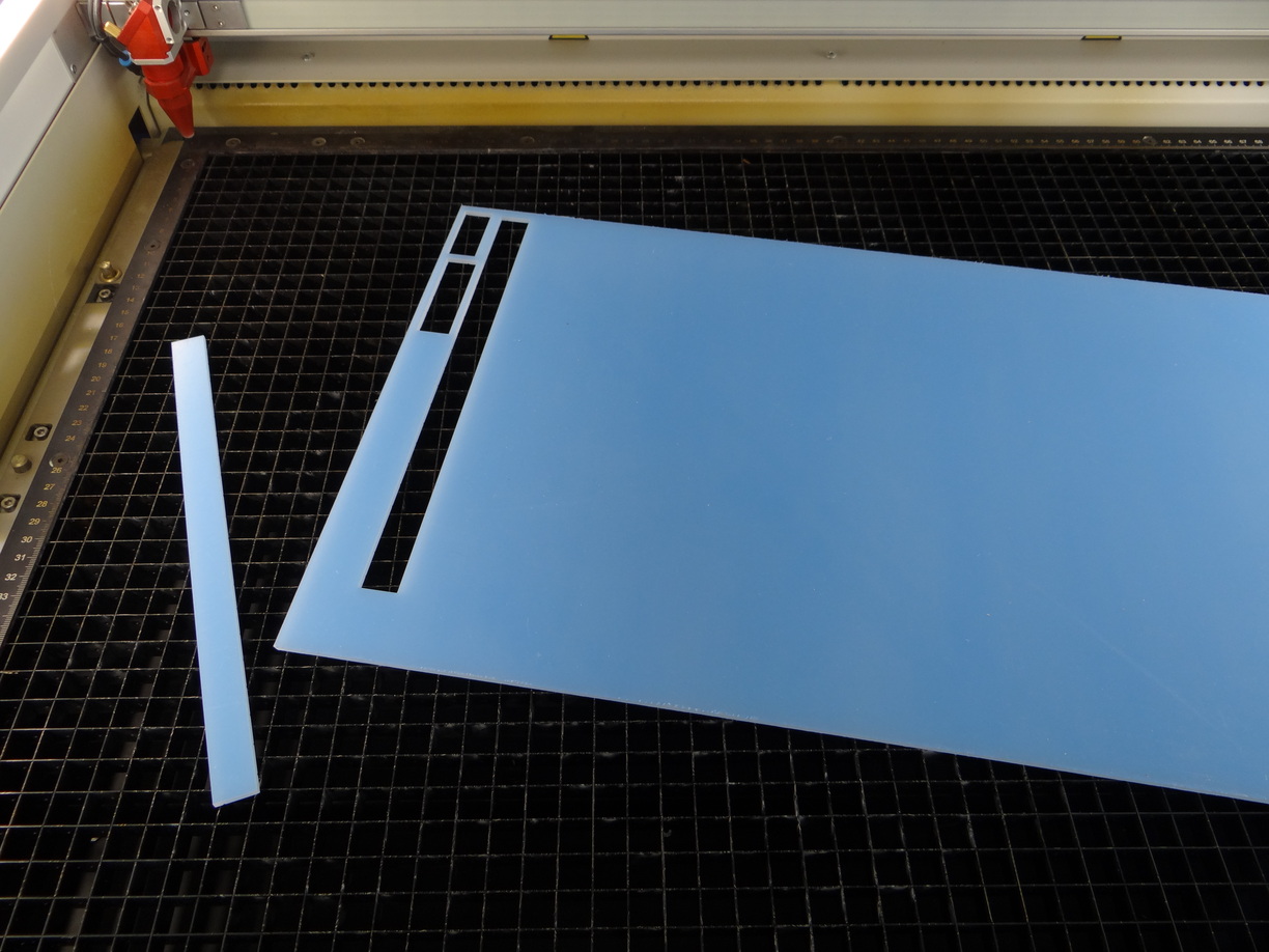
Ribbed obstacles
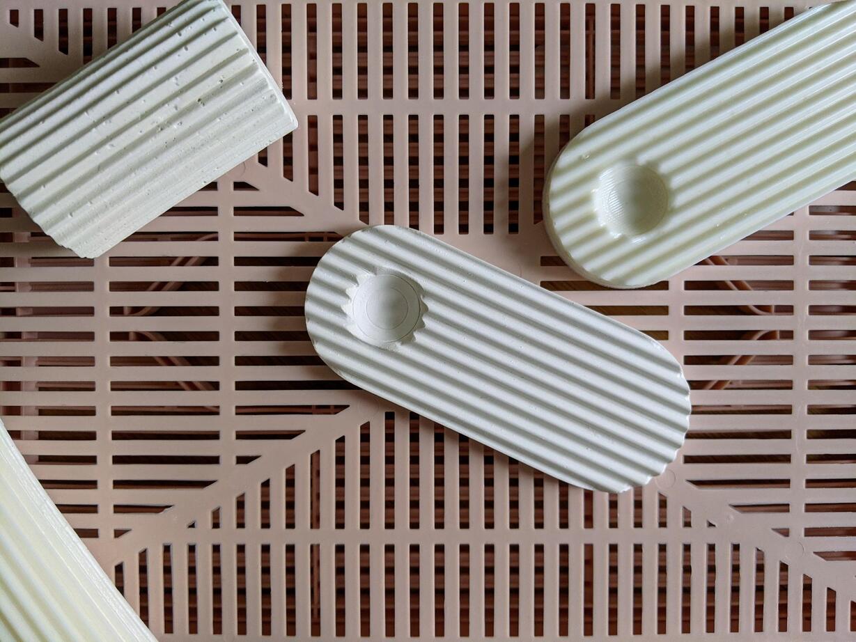
Molded parts in polyurethane and plaster during Week 12 - Molding and casting
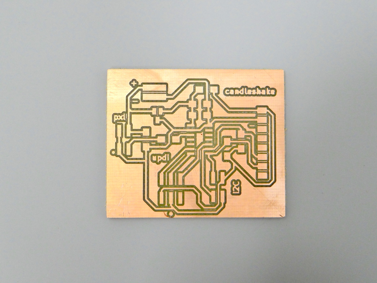
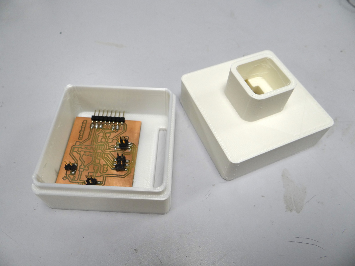
I2C communication between color palette and light sources
The I2C communication between the color palette board and the light sources boards coded during Week 13 - Network and Communication
Drafts for the presentation - Week 17
Background music: Dixit Dominus, Haendel (1707) which accompanied me for many fabacademy hours. Live recording of my choir this april 2023!

Week 1 - Initial thoughts
Initial thoughts for my Fabacademy final project
I want to create a modular device focused towards experimentation and not so much function-oriented. I wish to work on something reconfigurable, not a static object that will have only one place in my life. And maybe which could find a place in the life of some other people.
I started writing down some very general ideas that would interest me to work on. Here are some of them that actually led me to my first idea.
textures, materialslight, light filters and diffusionhide the technologycreate a tool
After some brain processing here is the idea that emerged:
A tool to experiment light art
You might be used to practicing art through a variety of media, thanks to some tools or instruments. Maybe you have experience performing graphic arts such as painting with watercolor, or drawing with pens. You might also have skills producing and arranging sounds with the help of a musical instrument or a computer. My intention with this project is to provide a small set of tools to explore light in an esthetic way.
Light interests me as a medium because most people - including me - don't have so much representations about light art. One will have less stereotypes about what a light creation would look like than about a renaissance piece or a techno track. All the representations, all the codes of light aesthetic are still a bit vague in our minds, which could let us explore quite freely that discipline. I also believe one can have an immediate and intuitive sense of light aesthetic, because it is such a natural feeling that we experience all the time. Most of the time, we don't act consciously on light, we are not even paying so much attention to how it interacts with our world, how it gives us the sense of color, depth, texture. So I am very curious about creating such an environment for people to discover how does it feel to manipulate light and to create their piece of light!
Prior knowledge and inspirations
Creating a set of tools before the practice being very formalised can be confusing, because I also have ton invent the rules, and I have no prior knowledge in light art. I have even no prior knowledge in color and light in visual arts such as cinema, painting... I can imagine there are a lot of keys to understand light, for example how the shadow is colored compared to the light, and some rules or tips in the use of light, for example in movies. On another angle, I studied basic optic science during some physics lesson in my scholarity, but that felt more like scratching the surface of a much more complex discipline. So, I believe I'll get more familiar with light while making and playing with my device!
I am also conscious that a lot has already been explored in light art, that there are some famous artists, amazing pieces, and I believe that there is a lot of research and innovation in particular in digital arts. For now I'm really not putting myself in an artistic position neither academic, more like a tool-crafter learning by doing and playing.
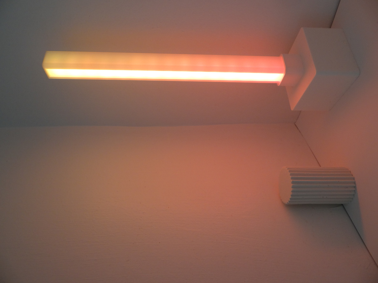
About the inspiration, I can remember visiting an exhibition of Dan Flavin's art in Paris when I was not yet an adult, probably at the Musée d'Art Moderne in 2006. I think my feelings about this exhibition were both upset, as you can be when you see a so simple setup being under the spotlight of major art show-business, and enchanted. It is described as minimalistic art - and you can see why on this picture - but yet I was very impressed by the beauty and strangeness of this experience.
 Photo: © 2016 Stephen FlavinArtists Rights Society (ARS); New York
Later, I got really interested in digital art in general, and followed an interdisciplinary master called Art Science Technology in Grenoble, France. I regularly visited digital art exhibitions, and light installations were quite common in such places. But I cannot recall any piece of art I saw that focused only on light, I must have forgot these. During these years, the Fête des Lumières in Lyon was also driving more and more attention and I attended several editions. Nevertheless it was at that time mainly focused on light projections and music-and-light shows.
In my personnal projects I also have a tendency to put led strips everywhere, starting with my clothes!
Feeding my interest in light I can also mention:
- a discussion with a friend about the color of the shadow in painting
- science videos about light principles and more generally wave physics
- playfullness and pleasure I get from arranging colors
- a piece of furniture and a piece of art seen at the exhibition Colors, etc. at the Tri postal, Lille, based on dichroïc properties
- a collaborative project I contributed to with the Fablab Carrefour Numérique, resulting in a diorama concept
- an exhibition I visited with a flashlight in Grenoble allowing us to appreciate all the texture of some historical stones (the context is very vague in my mind but I kept this observation about texture with me)
- how I experience light in my everyday life
Defining the device
Honestly it's way too fresh in my head to have an idea of the designs, even the list of elements I want to create are not clear at all in my mind. I am quite convinced I'll discover new directions while going further and experimenting the first bricks of my project. But here are the first thoughts anyway.
Guidelines
I have in my mind the following expectations about my project:
-
Modular- It is a set of tools that you wouldn't use all at the same time, depending on what you want to create or explore. Thus you could have several types of texture pannels, a choice of windows to frame the light, various filters to place in front of the light source, etc. -
Playable- I would like to give access to the large possibilities offered by programmable LEDs, but without modifying the code manually each time, nor using a web interface or something similar. I want to explore the gesture a person would use to play with the device, and define controls according to what may feel more natural, logical and fun. -
Unpredictable- This project is about exploring a medium, so of course it will be quite unpredictable in a certain extense, because one wouldn't know precisely the result of their action before doing them. But also I want to erase the sense of the code and numbers that underlies the device, in particular regarding the color coding. So I am not aiming at total unpredictability, more at a way to prevent the total-control thing.
Also, it is important to mention that at that stage of my project, I mostly want to observe the light diffusion in space, and not the direct emission of LEDs nor something like a screen.
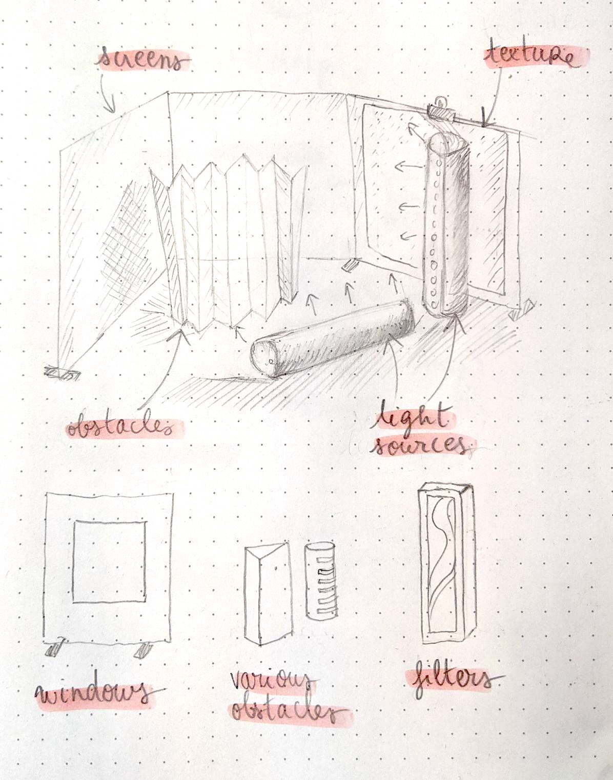
Elements of the set of tools
Elements that could be provided
Here are the roles I am hiring:
The first roles:
light sources
I could use any kind of light source, but it would be a shame not to rely on programmable LEDs. As I said I see them at first as sources of light, but if they're good looking and can also play an aesthetic role for themselves, that's even better.
screens
I need at least one screen to observe light and shadows. That could be a simple piece of paper. I prefer having several screens to take advantage of the 3D property of that medium. It could be some kind of folding paper screen
obstacles
Technically obstacles are also some kind of screens because they'll interrupt light on a surface. Obstacles are placed before the screen so you can also observe how lights create the volumic sensation, how the different surfaces are lit. Moreover, they cast shadows on the screen, that you also want to observe. I imagine them totally white, they could be some paper foldings and/or wood simple shapes.
The secondary roles
In addition to these first roles, I could also provide:
textures
Monochrome "2D" textures, such as textile, corrugated cardboard, heavily textured paper, or reflecting surfaces. They could act as a mix between screens and obstacles, and be placed either on a screen, or in the middle of the scene.
filters
Placed on the way of a light source, they could change their property (like a dichroïc polarizer) or their diffusion
windows
Some sort of negative screens: they block the light except in a window cut into a pannel. They allow to structure light effects visually.
lenses
I am not looking into a scientific light experiment approach, but it may be useful to use some lenses to focus the light.
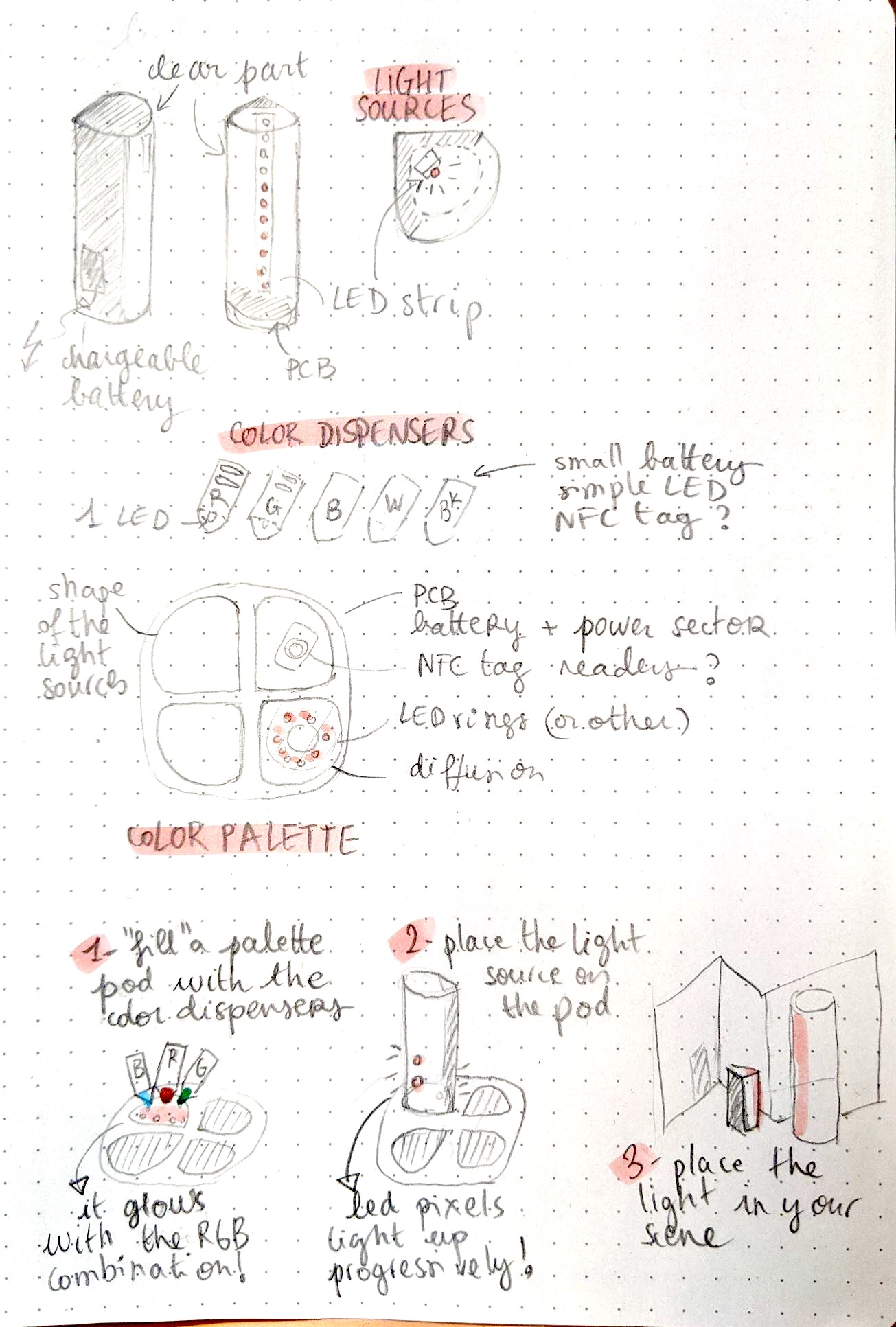
The led controls
primary color dispensers
I would like to give the possibility to mix the primary colors (of light, which are red green and blue) as one would mix gouache painting colors. I'll have five color dispensers:
- Red
- Green
- Blue
- White (if I use RGBW leds)
- Black - to set the brightness
color palette
This is where you would mix your primary colors. Then you could "fill" your light sources with the color in the color palette to change them. If the light element contains several neopixels, they could be lit progressively if you keep this element in contact with the color palette.
mixing colors
If I use led strips, it would be interesting to be able to "fill" with a color either one tip or another, thus allowing to fill both tips with different colors. It would be quite fun to give the possibility to "mix" these colors with a gesture like shaking - for example to create a color gradient.
The environment
space structure
I don't know yet how to solve this question. I believe it's important to have a kind of definition of the space you're working in. For example in painting your space is your canvas. In music it would probably be time, and in theater both a scene and a duration. I thus would like to define a 3D space, maybe with pannels. These pannels could be the same as the screens, but not necessarily. Also, this structure could allow us to hang the lights (either mechanically with hooks or similar, or with magnets).
dark room
I'll probably have to work in a dark environment to fully appreciate the effect of light. So I'll need a small dark room or dark working place. Needless to say that this environment constraint will certainly affect all my elements design, as they need to be manipulated in low lighting conditions.
Development
If I stick with the project as described above, the minimum viable product would be the light sources and the color palette system. I will thus probably focus on these elements before creating a whole toolkit. Nevertheless I probably shouldn't wait until these minimal elements are fully functionnal to test if my general concept is relevant. Here's how I could organise the first development steps
-
assemble a basic led strip circuit
-
test what I can expect from the light diffusion
-
test the interaction of the light emitted with paper pannels, obstacles, textures...
-
evaluate the positions I would like to give to the light sources
-
and how the space should be structured
-
create a minimal color palette circuit
-
add communication components and code to the light source circuit
-
test the communication between the light source and the color palette
-
evaluate the gesture
-
integrate all of the above in the light source design
Then I can move forward to the next steps:
-
creating the color dispensers
-
test the interaction between the color dispensers and the color palette
-
take in account the light source design to design the color palette
-
explore the gesture
-
explore the sense of space and interaction with obstacles, screens, textures...
-
build some test elements (screens, textures, obstacles)
-
conceptualise the space structure
-
build it
-
test!
-
establish some coherent design rules to apply to all elements of the kits (if possible)
-
design and develop more elements of the kit (starting with the more importants, such as the screens and some obstacles)
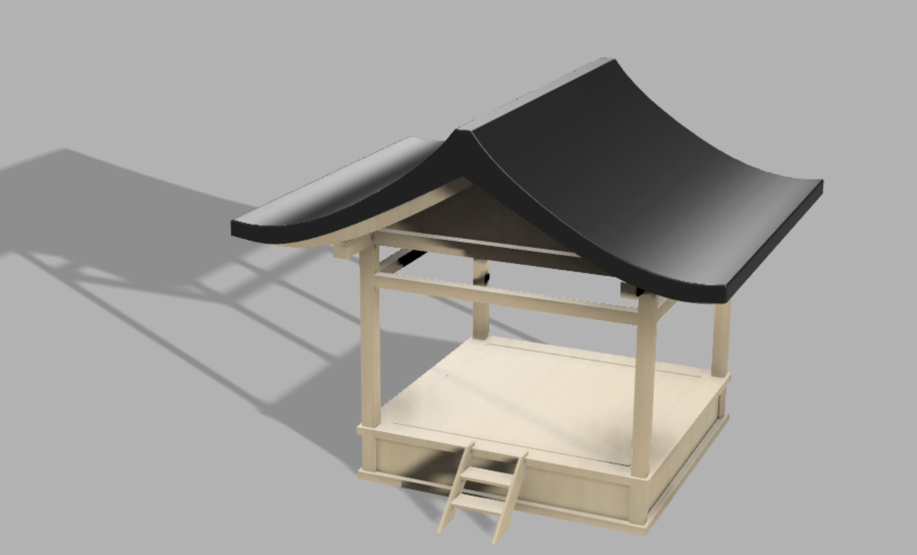
Week 2 - 3D Design in Fusion 360
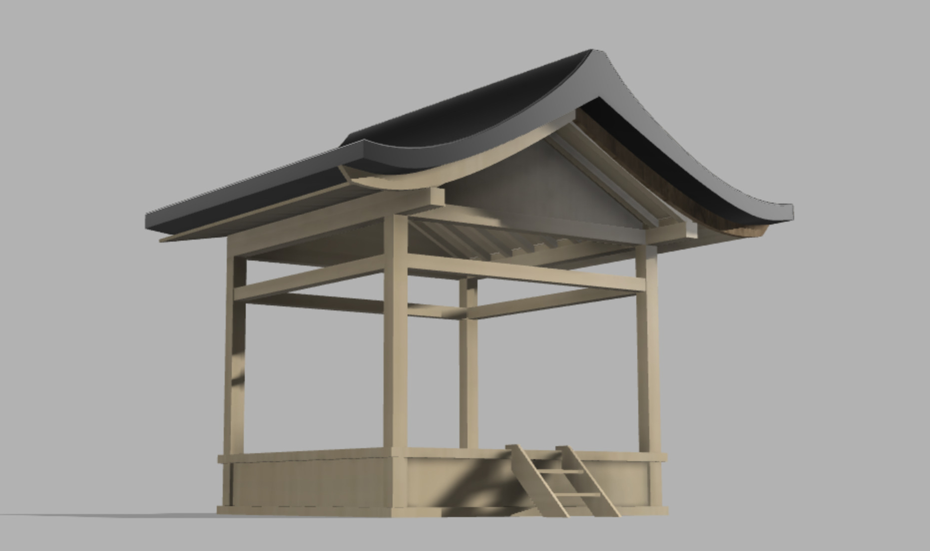
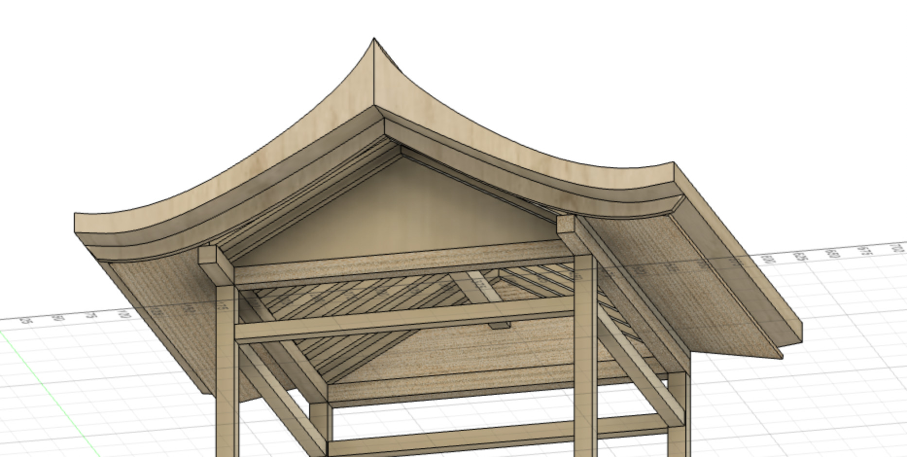
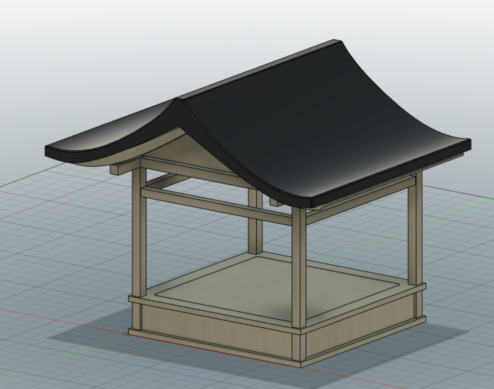
As explained in the previous week, I have to think about a space structure for my light toolkit. A theater stage felt quite logical for such a 3D exploration. Nevertheless I wasn't too much appealed by occidental traditional theater stage, which are opened mainly on one side - the public's side. I had images of more oriental stages, with openings on many sides, wood based and quite cubic.
I looked for "japanese small theater" and found that noh theater stages looked a lot at what I was looking for! They have:
- the wood minimalistic aesthetic that I appreciate
- a lot of openings : the pillars exactly structure space without restraining it and invite to much modularity
- the shape allows to hide light elements in the floor
- the japanese aesthetic goes well with my idea of paper screens
Here are some images of noh theater that inspired me. The upper one is the largest noh theater in Japan, located in Nagoya (see the image source) and the second one is the Oshimah noh theater in Hiroshima (photo taken for the Nohgaku theater company by Sohta Kitazawa).


I was eager to learn how to use Fusion because it's a very widely known software in Fablabs, and it looks both powerful and accessible. I'm really not so good in 3D modeling yet and had recent experience only with Tinkercad and FreeCad (I used more professional softwares such as Catia during my engineering studies but that was years ago and I don't remember anything about them).
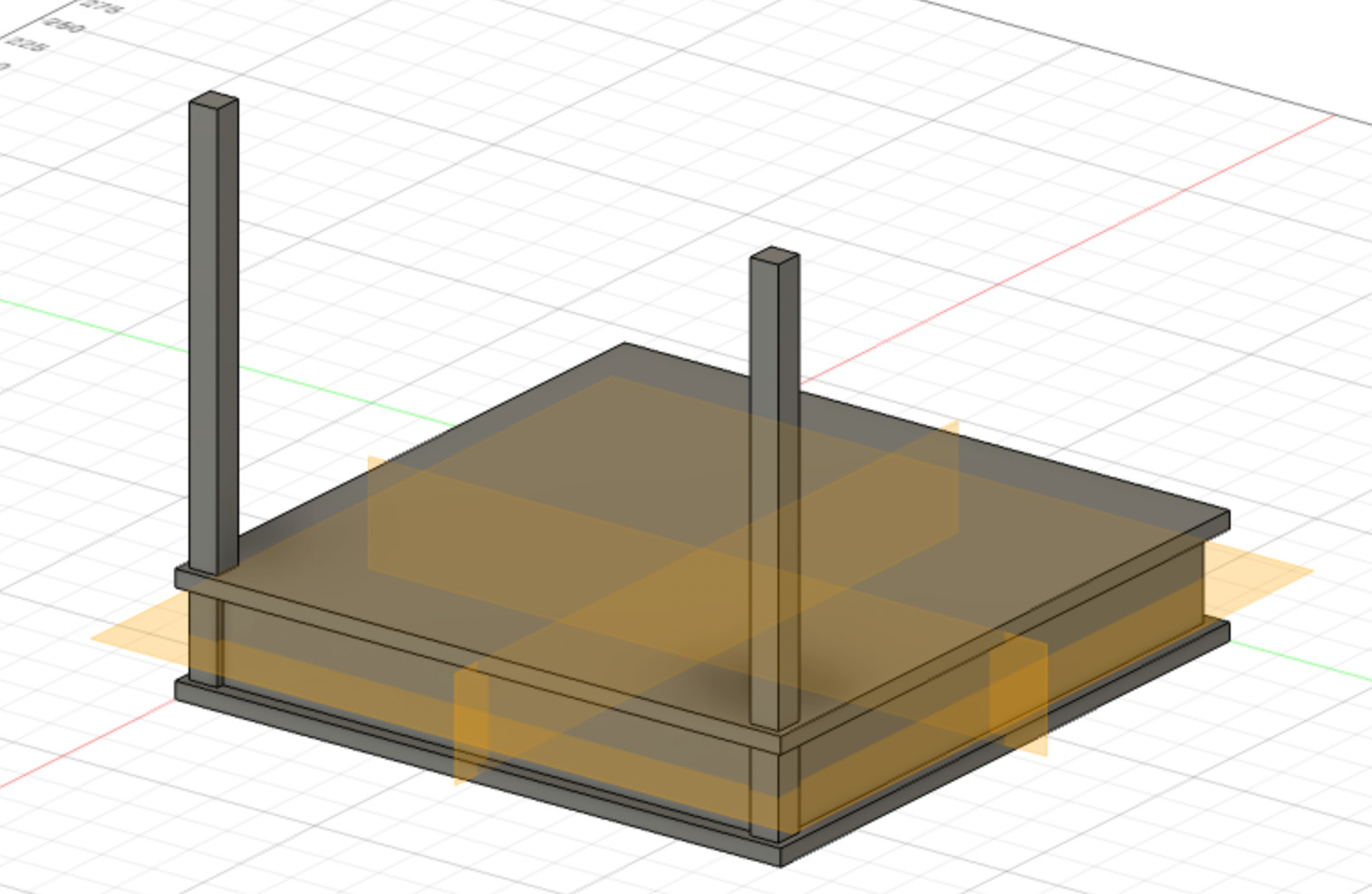
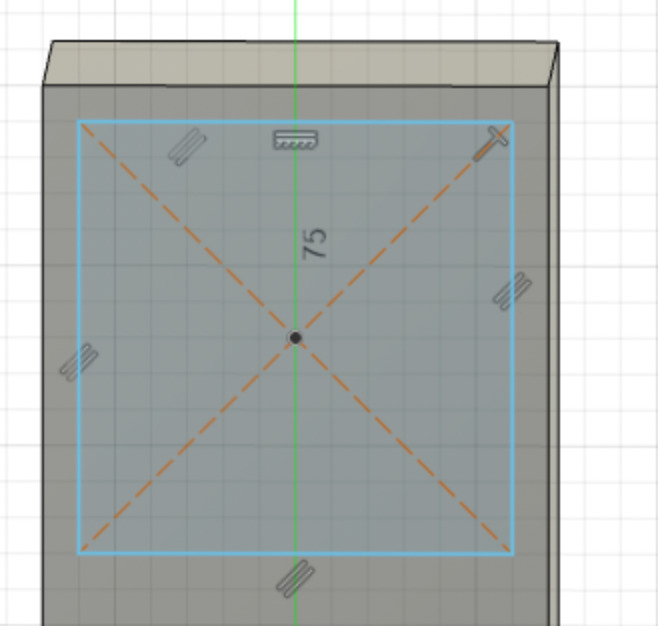
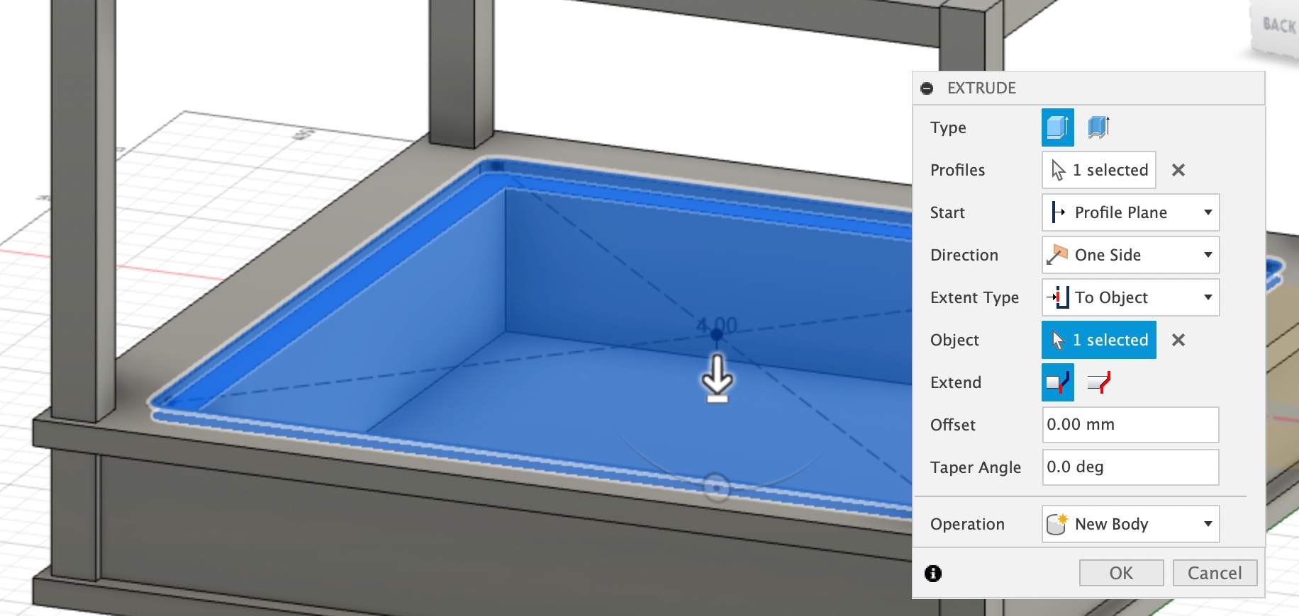
To create my noh stage inspired model, I looked at some pictures and plans of noh theaters. I will focus on the square main stage in the middle, and will not reproduce the gallery. If I go on with this idea, I may add the backstage behind the square main stage.
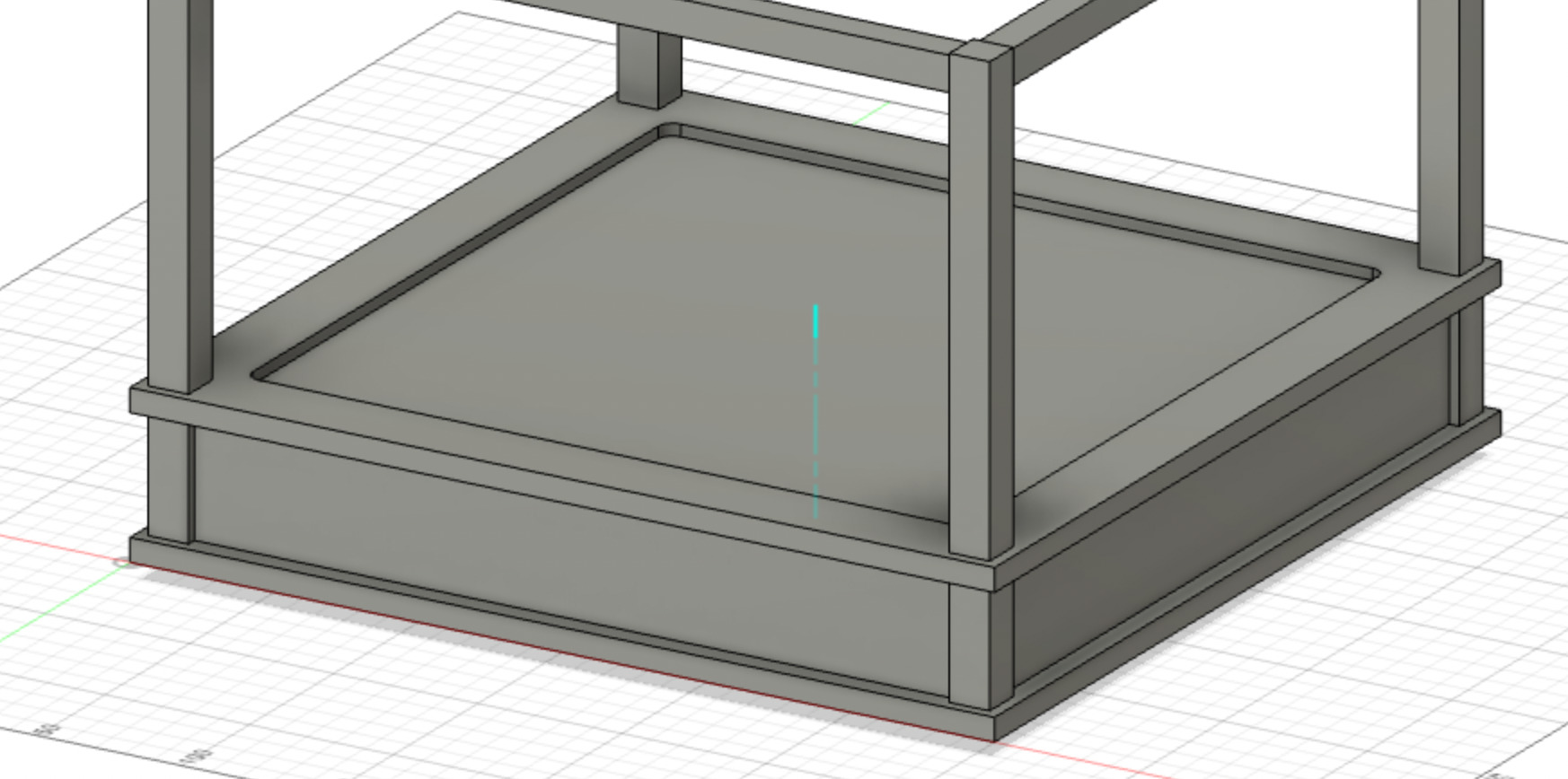
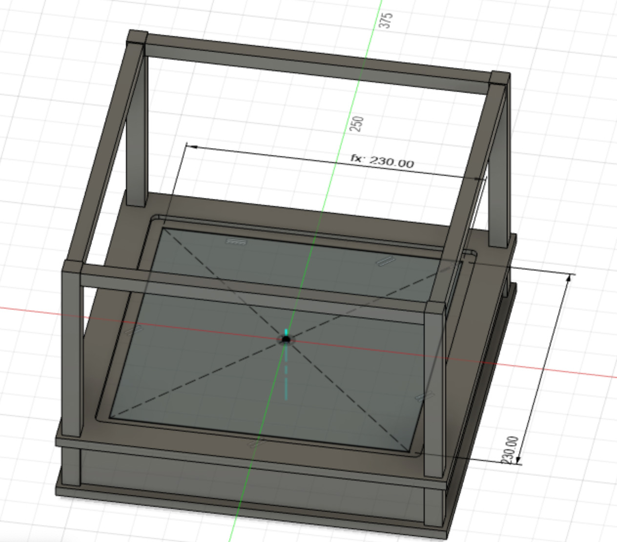
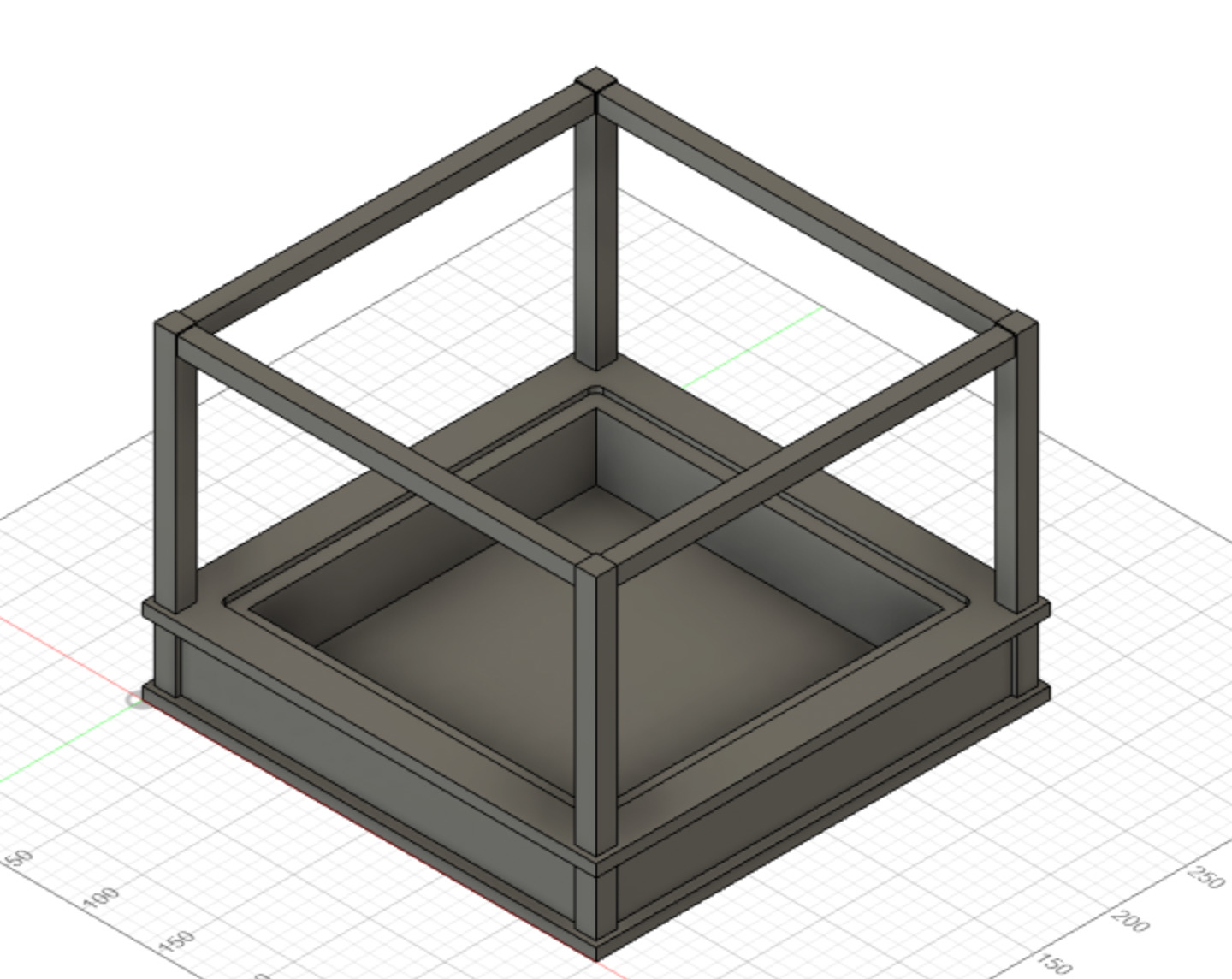
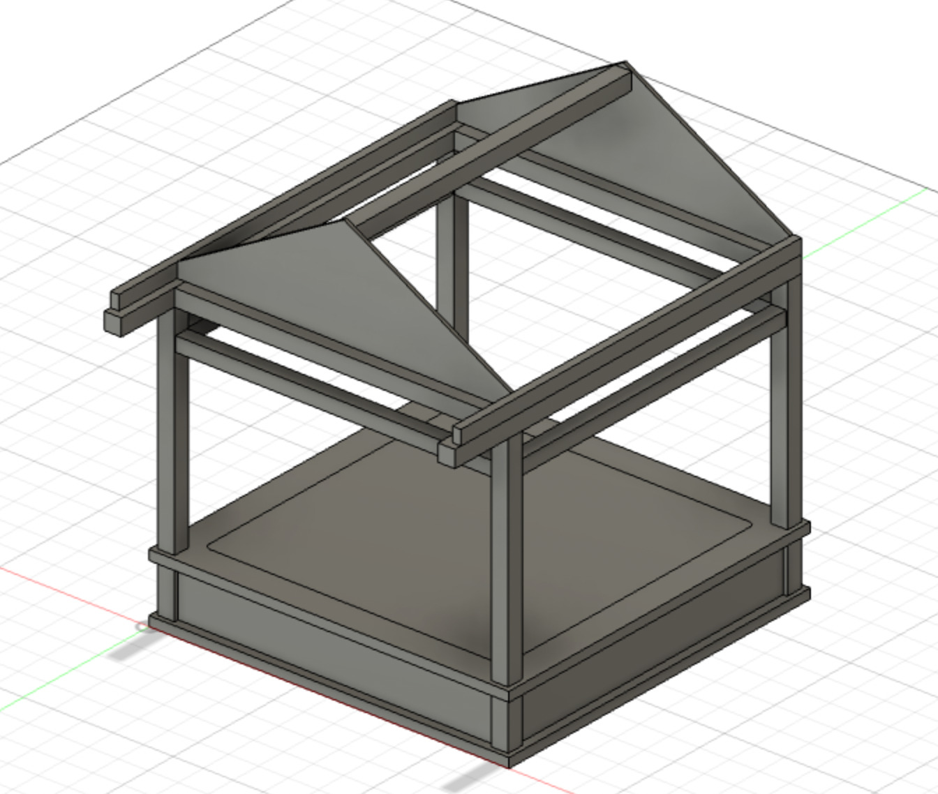
Here is the model I managed to create this week with Fusion 360:
Here is a short video showing the design process in Fusion360:
Main stage base, vertical and horizontal pillars
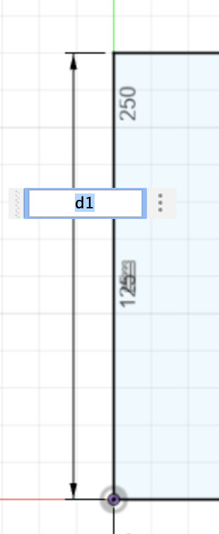
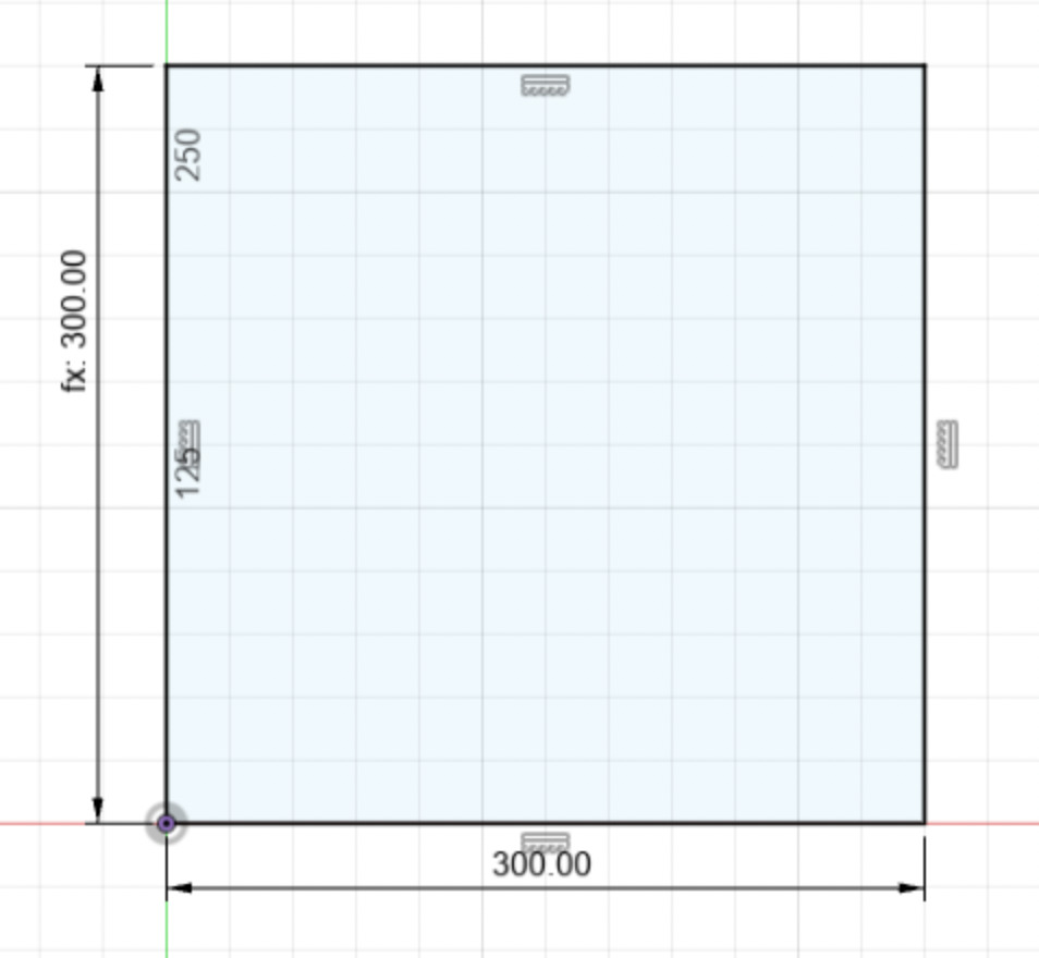
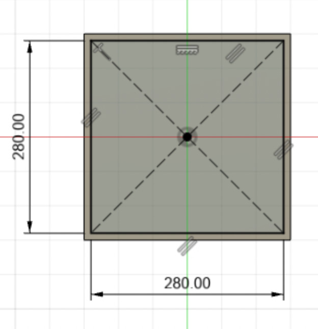
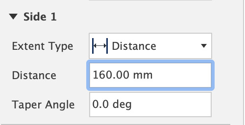
I started drawing a sketch on the xy plane (Create menu). I draw a rectangle with one corner coincident to the origin of xy, then adjusted its dimensions (Create menu while drawing a sketch). For now I didn't create a dedicated parameter, I just set one side length to 314mm and the other to d1, which is the dimension of the first side. Since it is a rectangle it has parallel constraints, I then have a fully constrained shape. I click on Finish Sketch.
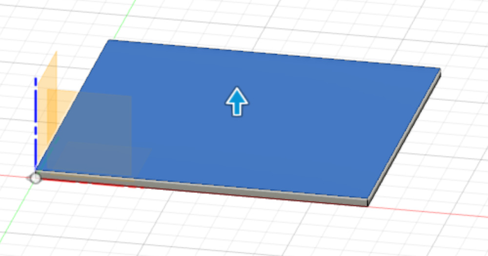
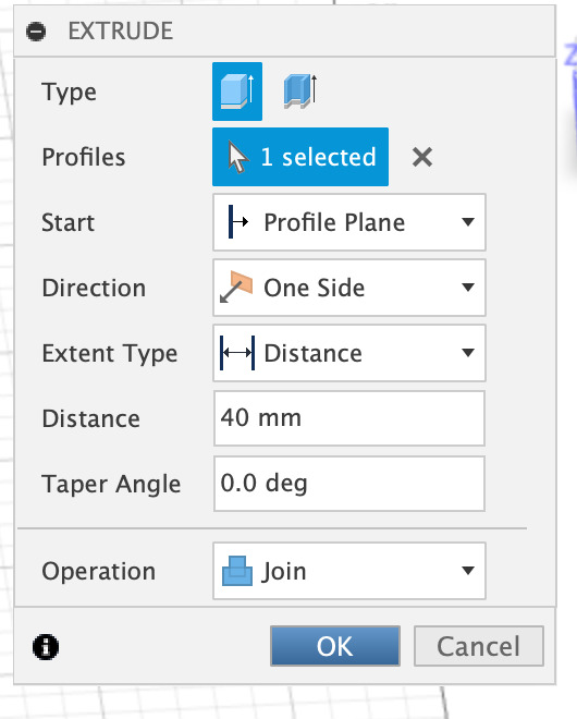
I then extruded the sketch towards the z-axis
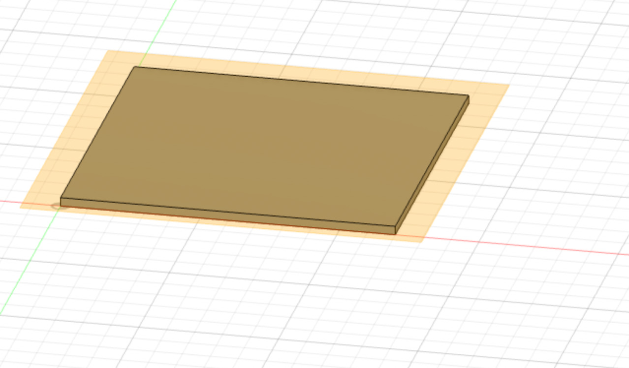
I created an offset plane (Construct menu) on the top surface of my shape, with the offset left to zero.
On that offset plane, I created another sketch in which I draw a centered rectangle. I linked one side dimension to the other as I did with the first rectangle. I then extruded it, using the default operation join. Afterwards I created a shell that you can see in the following screenshots, but finally I removed this operation later on.
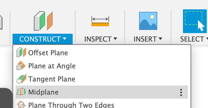
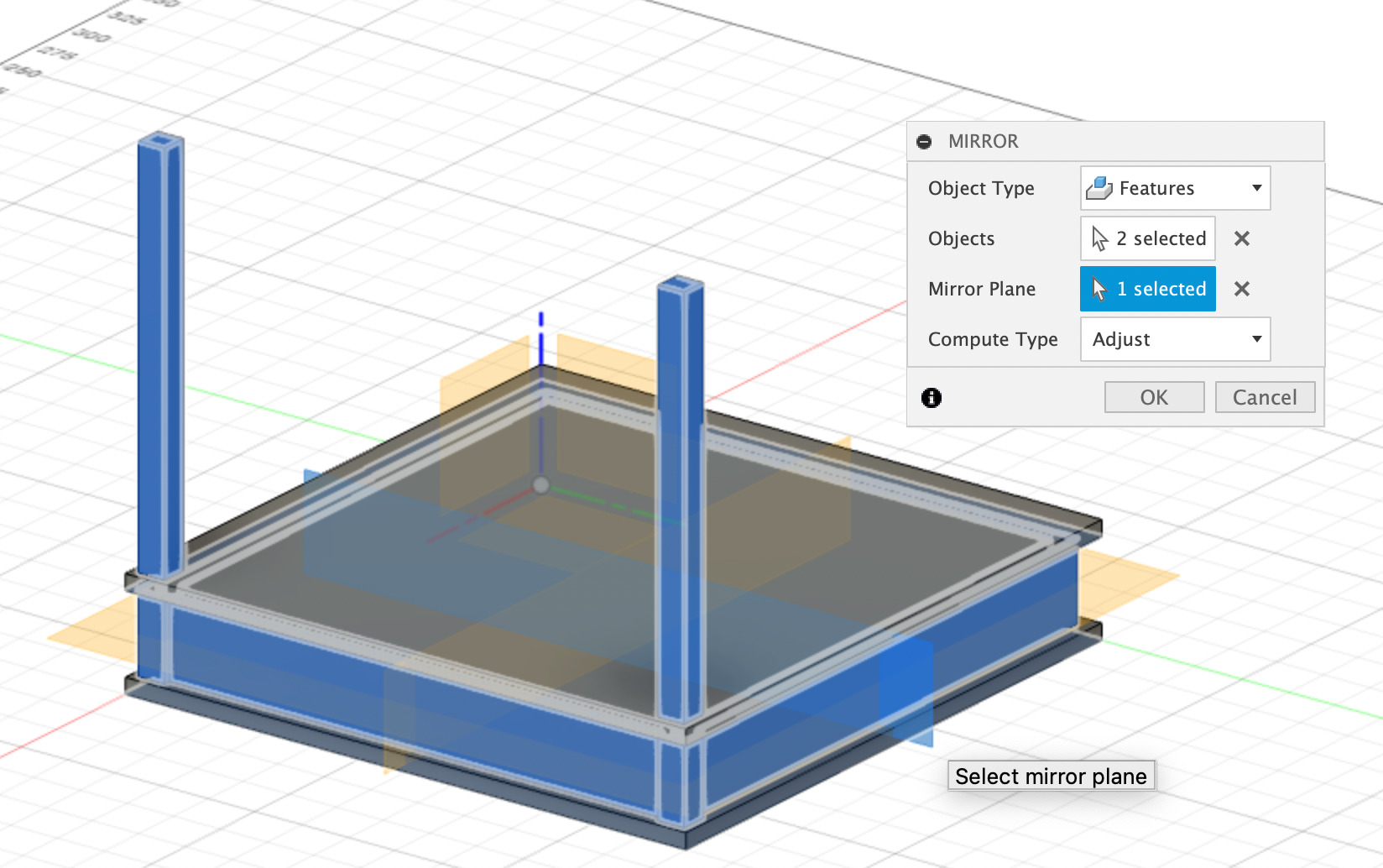
I created an offset plane on the top surface of my last extruded volume. I could then create a midplane (Construct menu) between the top plane and the xy bottom plane.
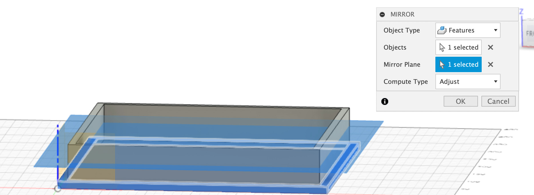
I then used the mirror feature (Create menu) to mirror my bottom extrusion relatively to the midplane created above.
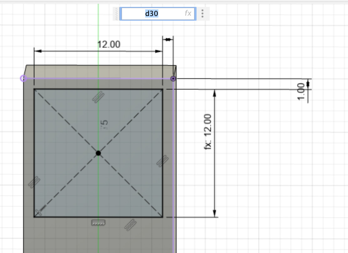
Time to create the pillars of my stage! I created another offset plane on the newly created top surface, then created a sketch.
You can see on my screenshots that at first I tried to project some bottom shapes to that plan (projections in purple), but finally I went another way and didn't use these projections. I traced a centered rectangle and specified some dimensions. Again, I didn't use parameters yet but made sure that the x dimensions were linked to the y dimensions.
I then extruded it to make my first pillar.
I created a first midplane by selecting the front surface and the back surface of the taller extruded square. It's parallel to the yz plane.
Then, I created a second midplane by selecting the lateral surfaces. This midplane is parallel the xz plane.
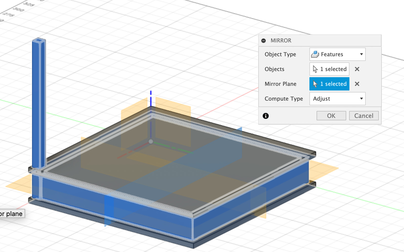
I could now use the mirror operation to mirror my first pillar relatively to one of the midplane (I started with the one parallel to XZ). Then, I mirrored these two features (the two pillars) relatively to the second midplane.
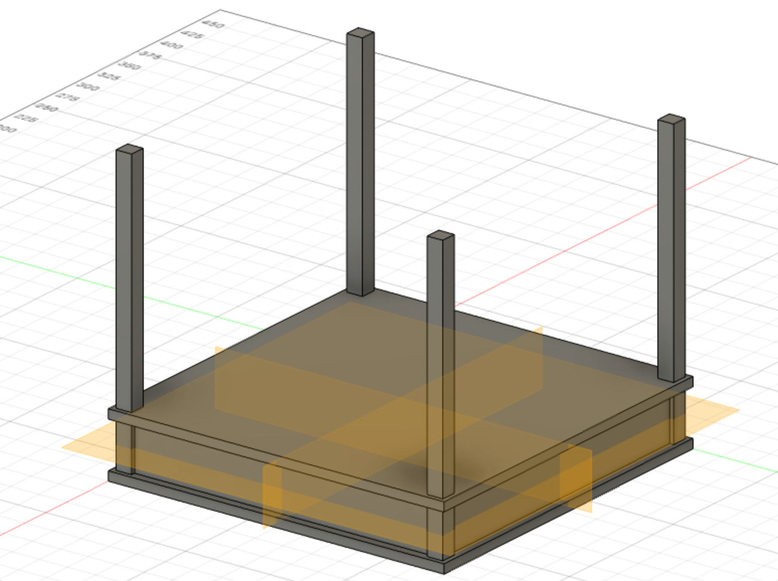
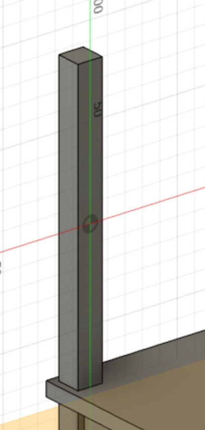
I now have four pillars precisely linked one to another. I decided to try another the pillar height. I then had to go back in a previous feature, which is the extrusion corresponding to the first pillar and modify the distance of extrusion.
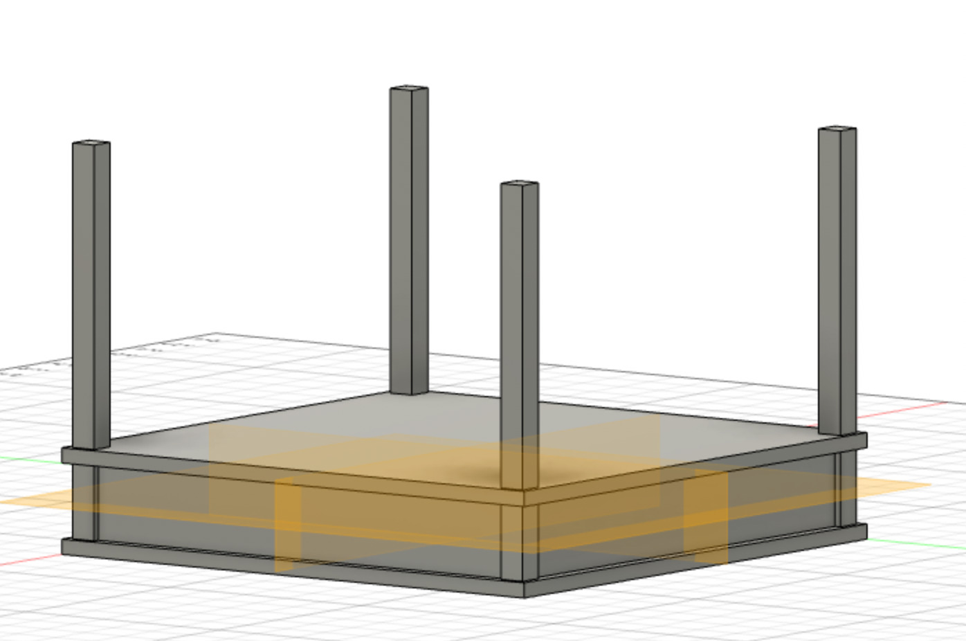
I could check that all pillars are correctly changing height at the same time. This is very convenient and I changed this height several time during my design process!
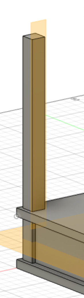
Then I created an offset plane on the intern surface of my parent pillar and create a sketch on it. The x and y axis allowed me to place a centered rectangle in the vertical middle of the pillar. I then linked the dimensions of my square in x and y.
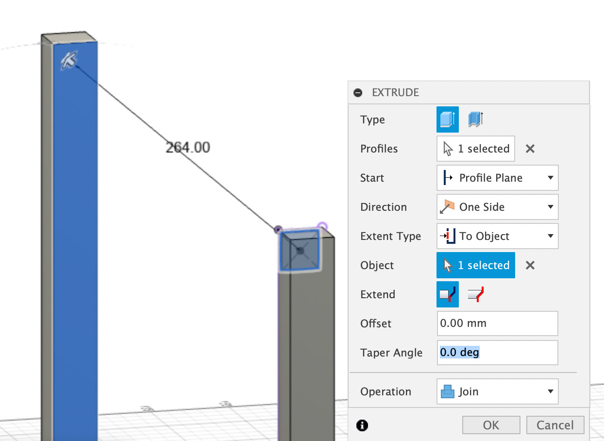
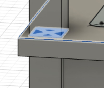
Once my sketch validated, I could now extrude it and choose the extent type "to another object"
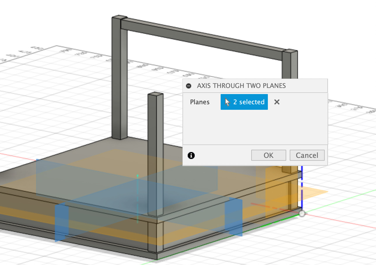
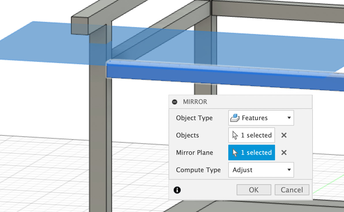
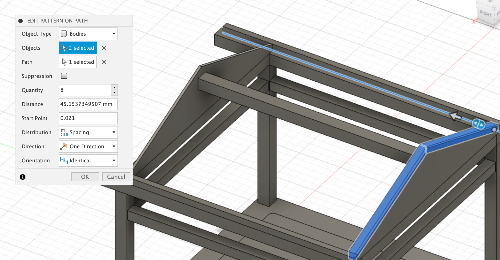
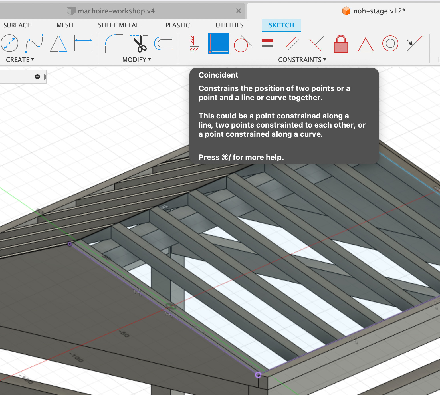
Then I created an axis through to planes (Construction menu) at the intersection of my two midplanes. This allowed me to create a circular pattern of my horizontal pillar, relatively to that axis. Note : I encountered a problem trying to do my circular pattern, I validated it but nothings happened. It worked when I changed the Compute Type 'Adjust' to 'Identical'. Not sure why though.
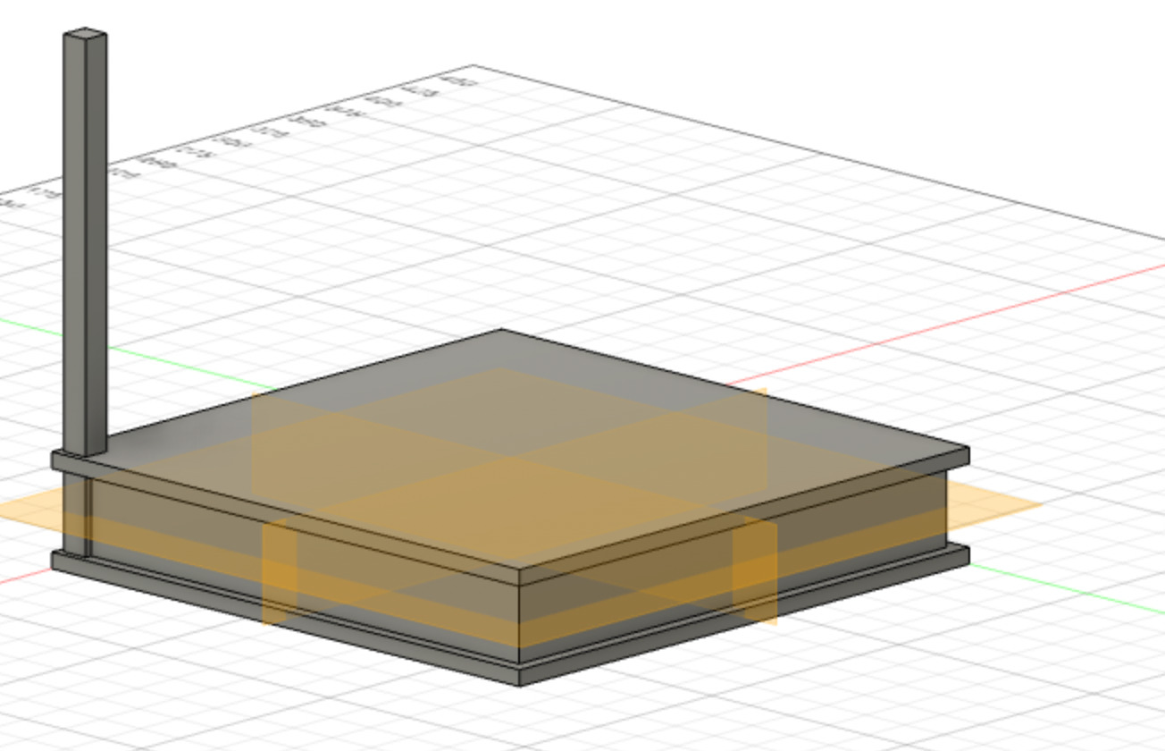
Here I have a good base for my stage!
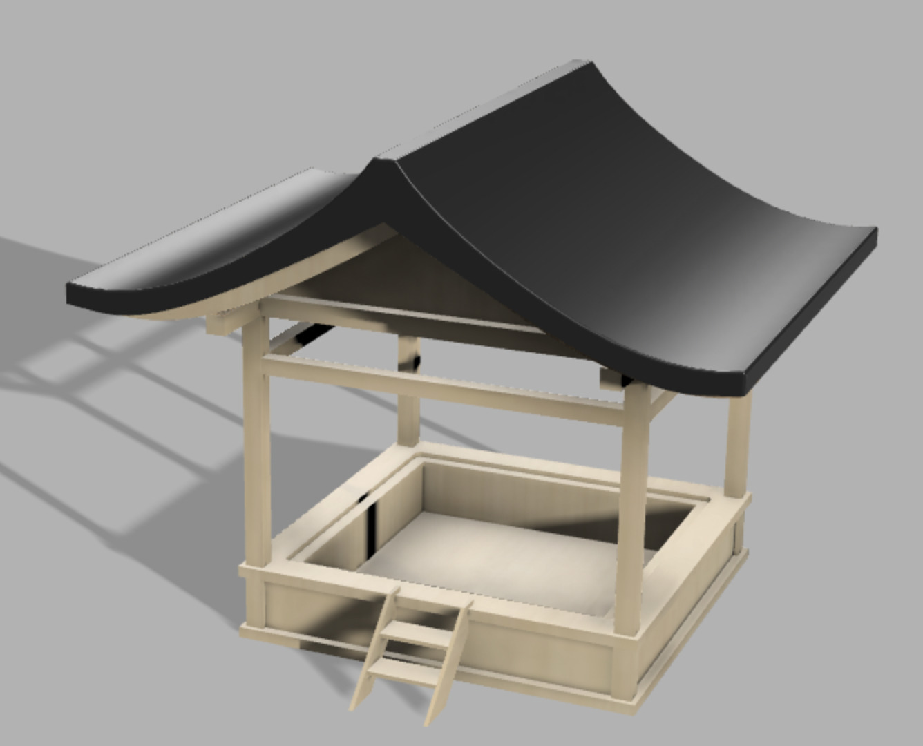
Movable floor
I want to be able to place some light elements inside stage. A removable floor will then be placed on top. I can think of several options that can be used alternatively in my kit: * A transparent acrylic floor * A semi-transparent acrylic floor * An acrylic floor covered with a thin layer of wood, to be able to see the light through it * A wooden floor.
I then created a sketch on my floor's plane, draw and adjusted a rectangle, filleted the corners and extruded it with a cut operation, to create the space for my removable floor.
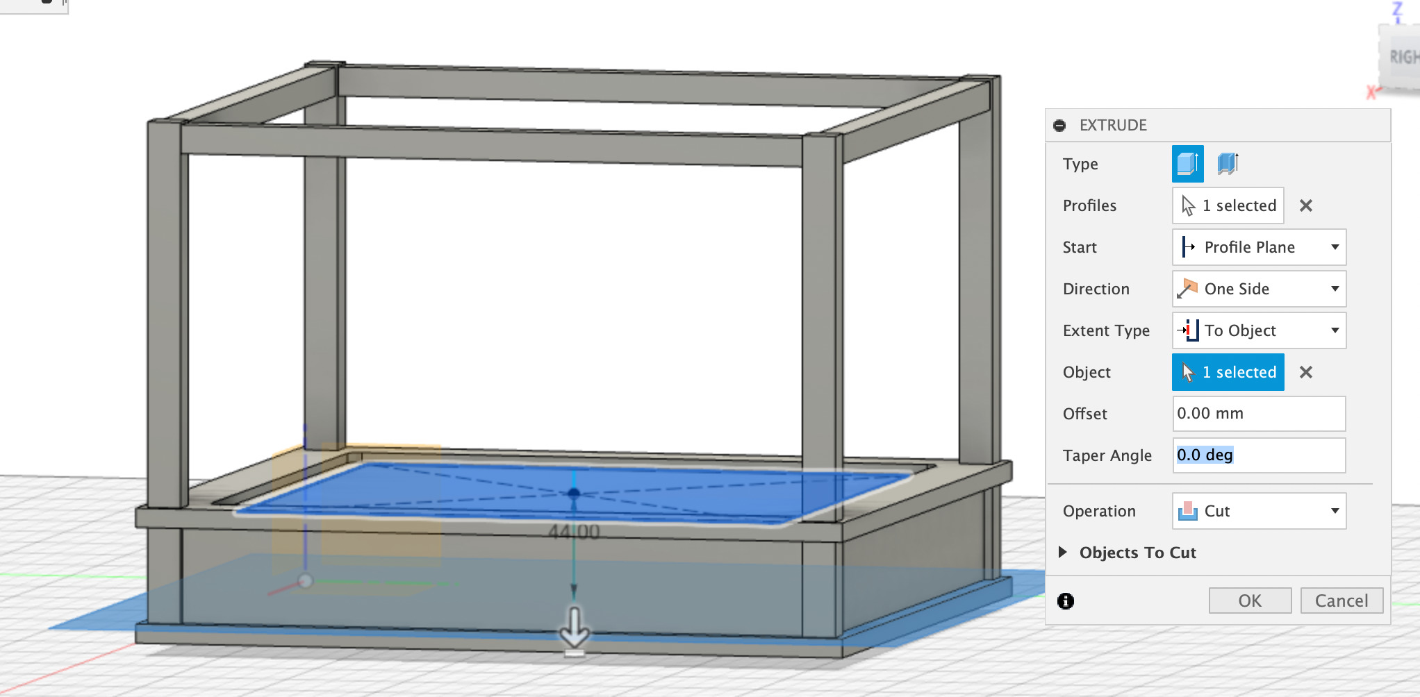
Next I had to create the space below to hide my light elements inside the stage. If you followed carefully you may have seen that at first I applied a shell operation to my stage. But finally I found it to confusing and hard to dimension correctly, so I removed that feature and created a completely new pocket inside my full stage. For this, I created a horizontal plane, then draw a rectangle in a sktech, added an horizontal offsetplane some millimeters above the original xy plance, anf finally extruded my rectangle with a cut operation and an extent to the offsetplane I just mentioned.
To complete my stage I needed to create a new body corresponding to my removable floor. I thus extruded my previous sketch (the one with the filleted corners) but this time with a New body operation. I rename this newly created body "Floor".
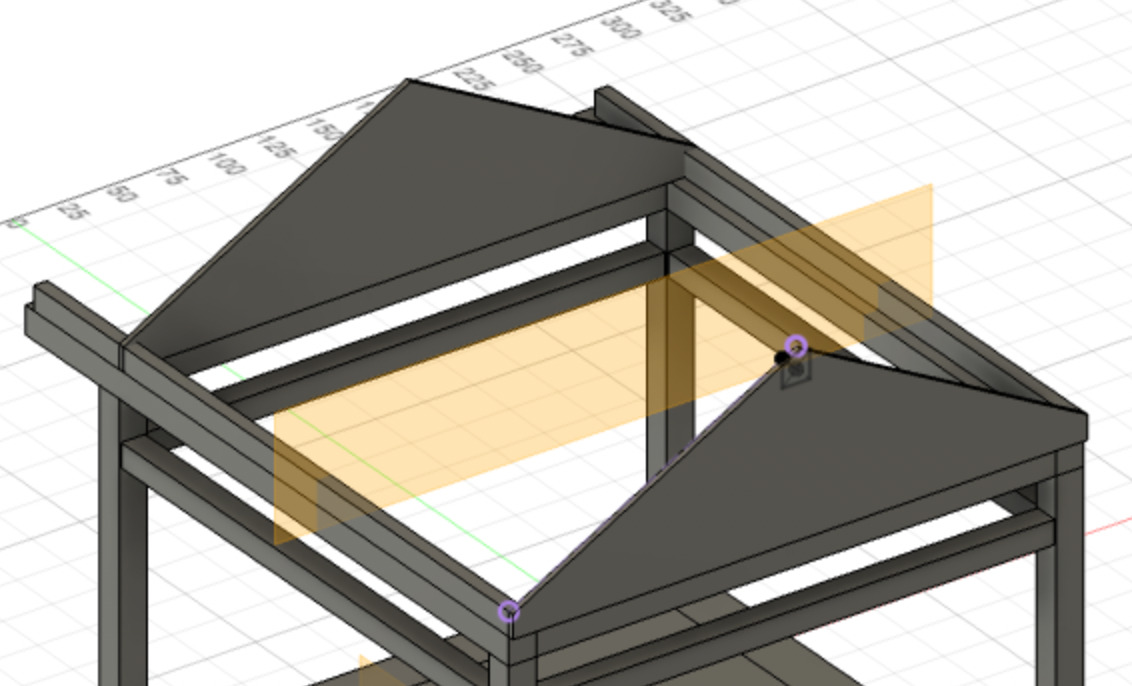
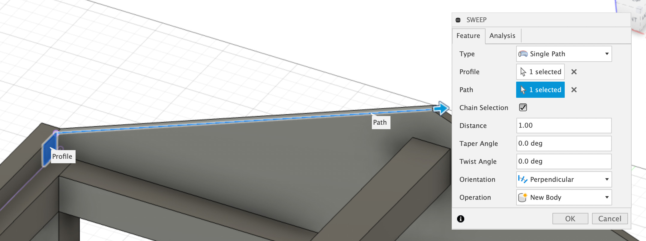
Roof structure
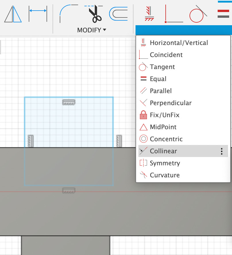
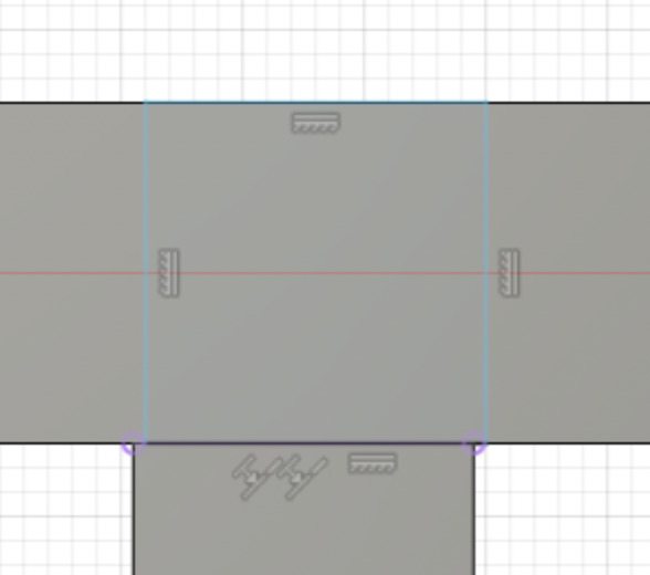
As it is very long to document each step individually as precisely as I did in the above, and also as I went back and forth in my design ideas, doing a lot of touch ups, I am only putting some screenshots. I mainly used the following operations :
- creating offsetplanes and midplanes
- creating sketches
- drawing rectangles / center-rectangles / other linear shapes
- adjust dimensions
- project geometries on a plane ('P' shortcut)
- coincident constraints
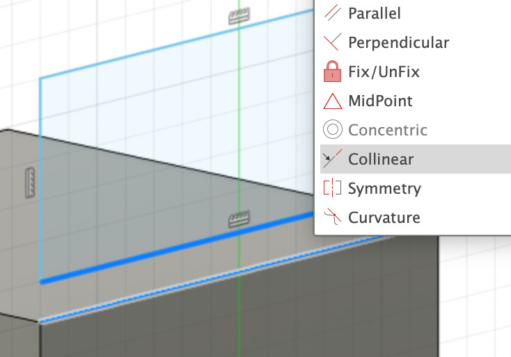
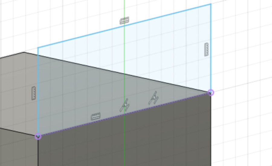
- collinear constraints
- horizontal/vertical constraints
- extrusion, mainly with the extent type 'to an object'
- mirror
- sweep
- pattern on path
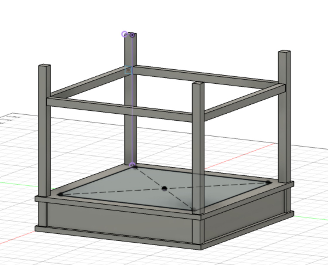
Above: modification of the vertical pillars heigth.
Finally I went in Modify appearance and chose a default texture to apply to my objects (with a drag and drop). I used alternatively oak unfinished and bamboo semigloss for the wood.
Testing the light elements
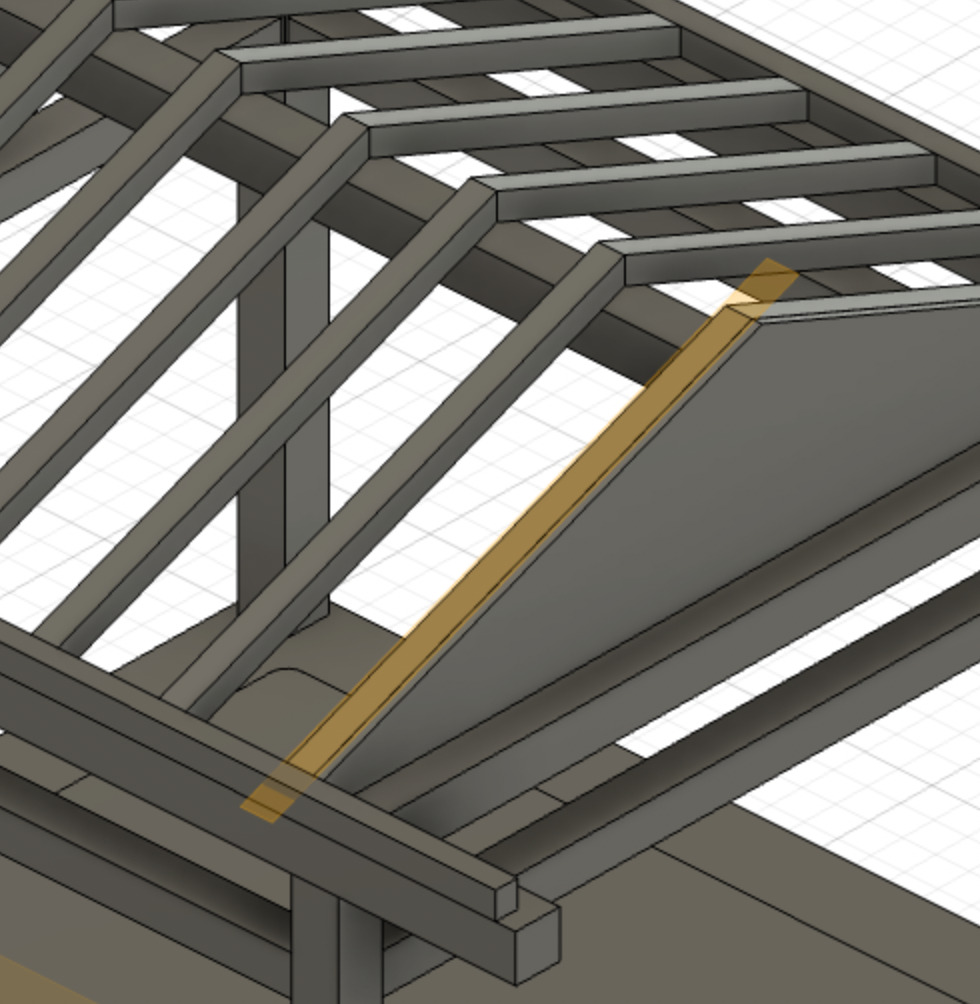
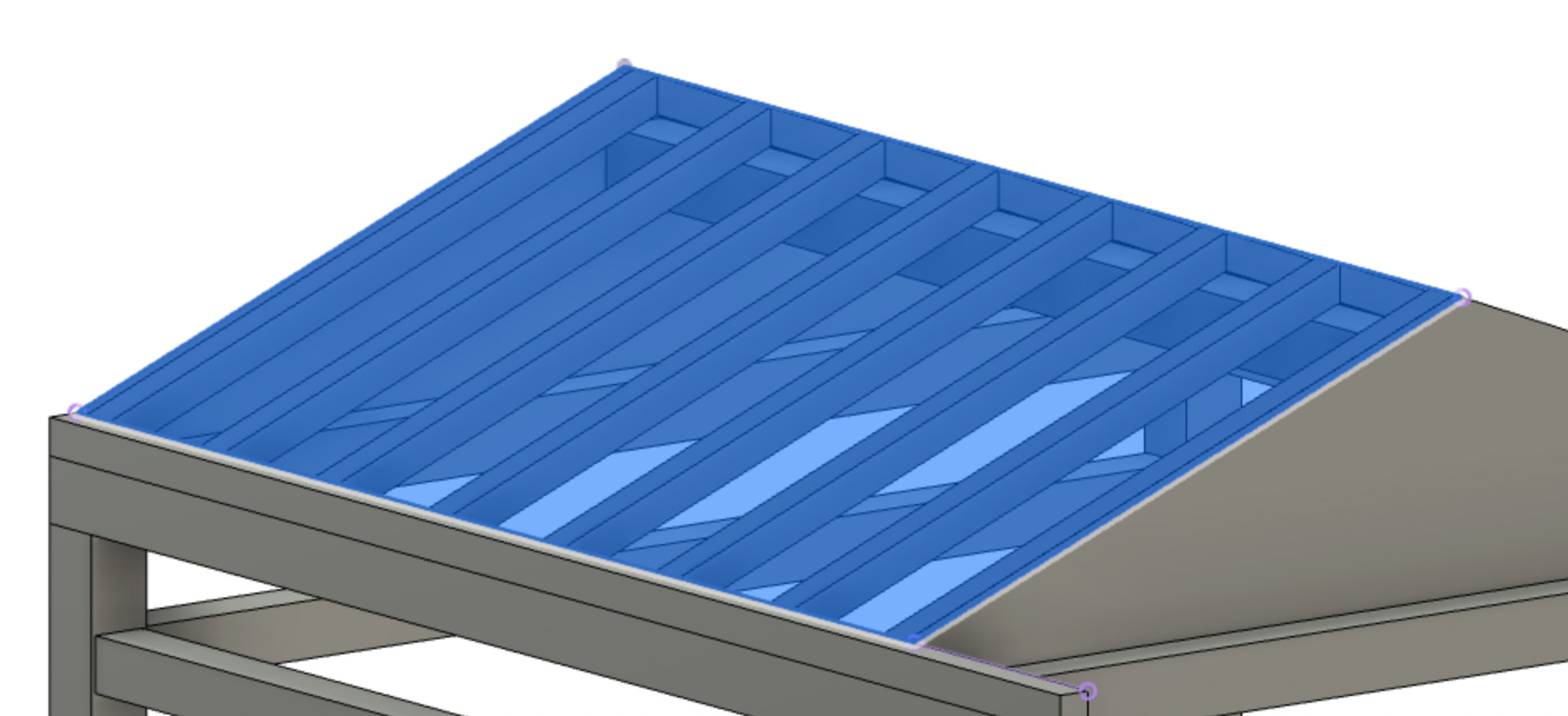
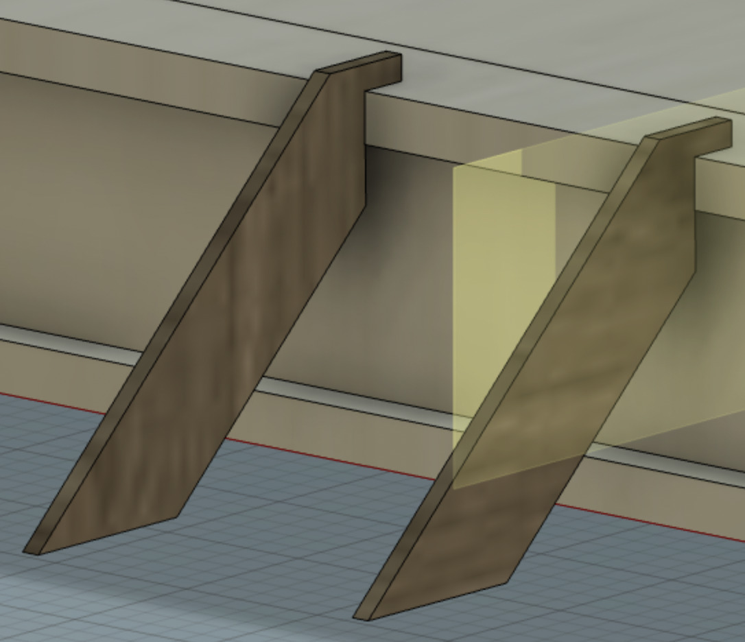
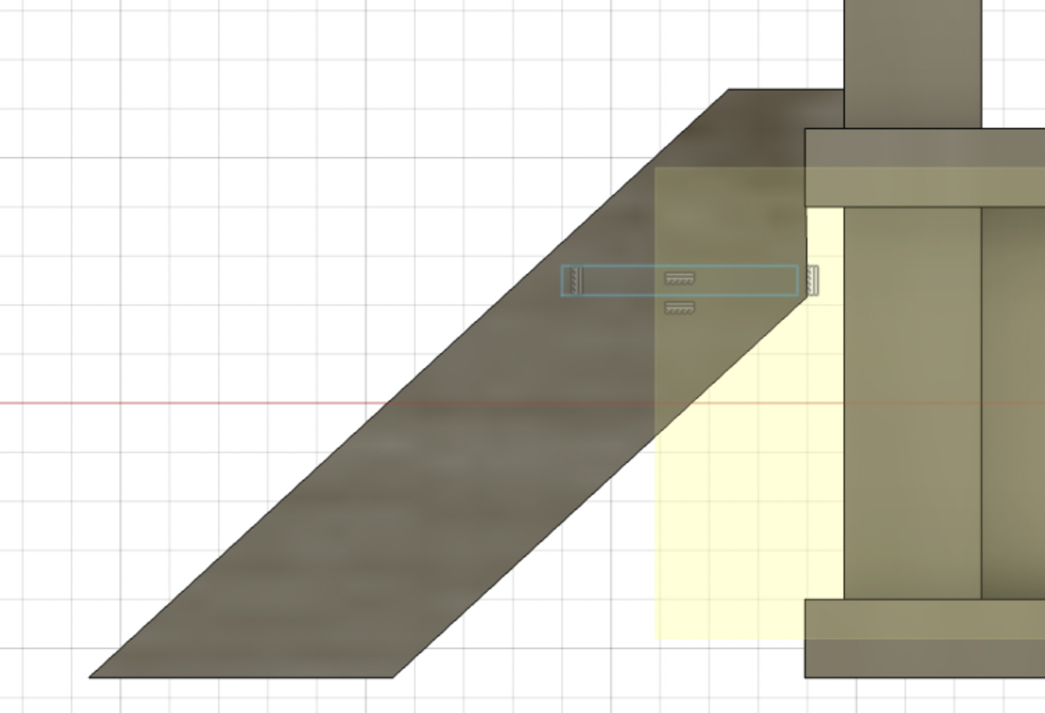
I took the opportunity of having my 3D stage model to think about where I would place my light elements. I didn't think so much about their design yet but I think they will be quite slim, with a led strip inside.
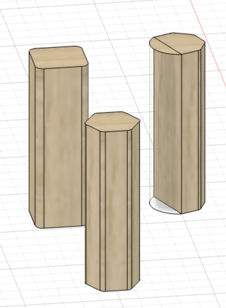
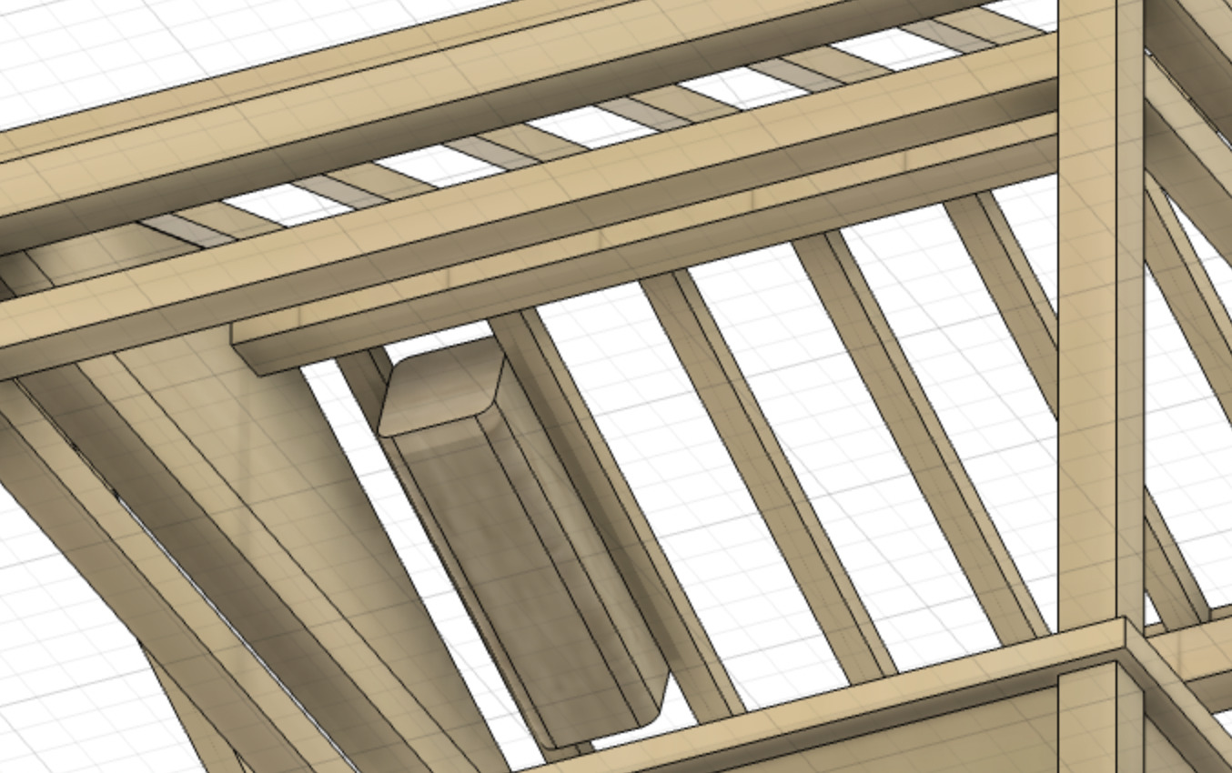
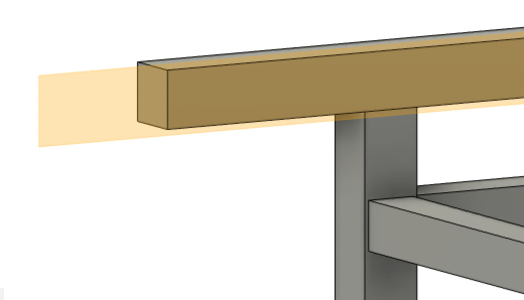
For the light elements, I made three minimalistic designs, then tried to place one of them at different places of the stage. You can see on the images that I wanted to be able to put some of them under the roof, maybe with some magnets. They would thus be between the roof's slats. But afterwards I thought that it would be too bad not to place them in other directions. I'll maybe place a false ceiling, a bit like a created a fake floor.
Fancy roof and staircase
For fun I added a fancy roof and a small staircase. I used the following operations:
- Plane at angle
- Sweep
- Project on a plane
- Extrude (join, new body or cut)
- Mirror
- Fillet
For the staircase I used:
-
Offset plane
-
Midplane
-
Sketch lines
-
Extrude
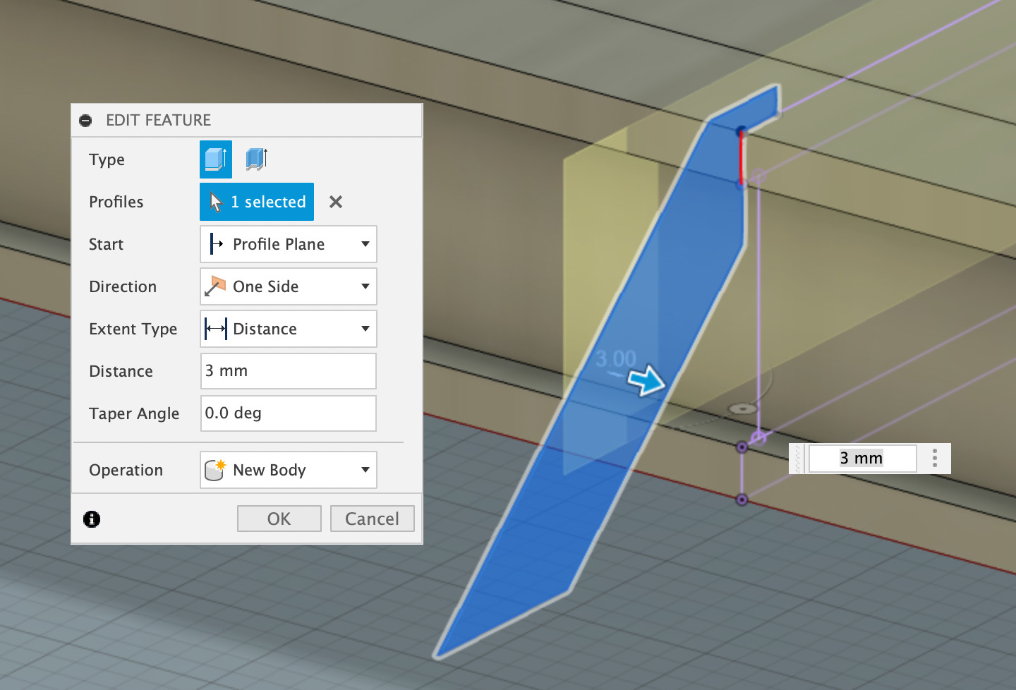
I went to the render window to calculate an automatic rendering.
Week 4 - Embedded programming
Controlling a neopixel through the serial monitor
Circuit and components
For this part I used the ESP8266EX MCU with the D1 dev mini board - because it was compact and worked just fine - but I could have use any other commercial board with an AVR MCU. I thus switched later on for an Arduino UNO (RFID section).
I experimented the serial communication by adding more LEDs to my circuit: one red, one green, one blue, and a neopixel RGB LED (all in my electronic components mess at home). For each of them I needed to place a resistor between the board pins and the LED +, to protect them. You can find typical values with a quick search on internet. It differs from one color to another. For the Neopixel, Adafruit's Neopixel Uberguide advise to use a resistor between 300 and 500 ohms. I used the resistors that I found at home, which were of 390 and 220 ohms.
Also as I will use again the PWM to vary the voltage and play on the brightness, red green and blue LEDs need to be connected to PWM output pins. The neopixel will only be controlled with binary information, so it's ok to use an ordinary digital outuput.
Here is the pinout of the board, indicating the pwm outputs with a wavy line:
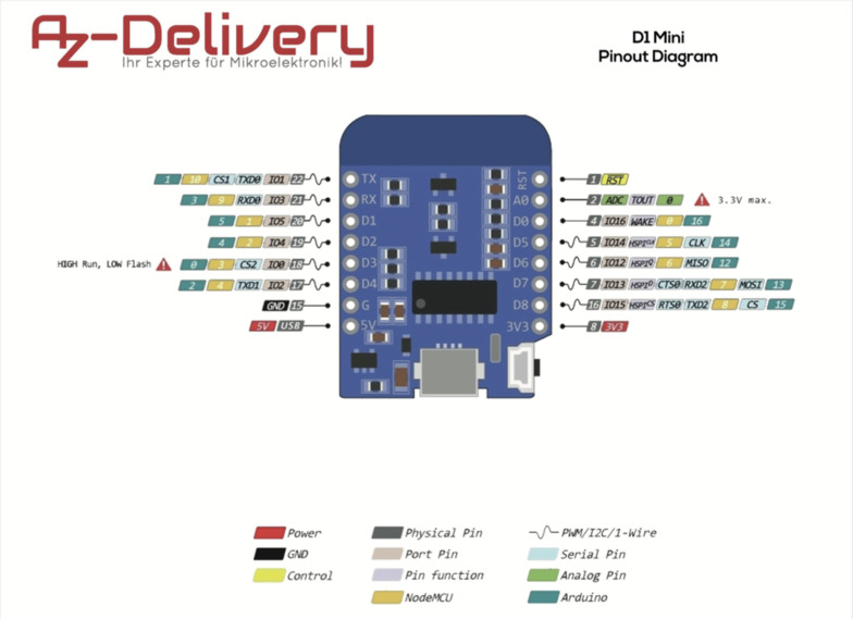
- RED LED on pin D5. Place a 390 ohms resistor between D5 and the LED +. - connected to the ground
- GREEN LED on pin D8. Place a 220 ohms resistor between D5 and the LED +. - connected to the ground
- BLUE LED on pin D7. Place a 390 ohms resistor between D5 and the LED +. - connected to the ground
- Neopixel on pin D1. Place a 390 ohms resistor between D1 and the data IN Neopixel PIN. - connected to the ground. + connected to 5V PIN of the board.
Here is a nice link to calculate the resistor value.
Libraries
Furthermore I need to install a library to controll the neopixel. The most used library is the Adafruit Neopixel Library. I thus installed it in Arduino IDE. Don't forget to include the library in your sketch with #include <Adafruit_NeoPixel.h>!
Sketch
The goal of my skecth illustrates one functionnality I want to have in my Final project. It corresponds to the color pallette. Indeed, the color pallette is like a paint pod where you would mix primary colors: red, green and blue, and also black to diminish the brightness. I thought about mixing white if I use RGBW LEDs in the future, but for this week I will refer to 'turn off the LEDs and reset the values' when you'll see the word 'White'.
So to sum up I'll ask the user to enter successively a r value between 0 and 255 that will both change the brightness of the red LED and set the 'R' color value of the RGB neopixel. Same for green and blue. Apart from being a demonstration of serial communication, it is also a sort of pedagogical device to understand how RGB color mode works.
//D1 mini

#include <Adafruit_NeoPixel.h>

#define LED_R D5
#define LED_G D8
#define LED_B D7
#define PIX D1 // Pin where I connect my neopixel / neopixel strip
#define NUMPIXELS 1 // number of neopixels. Only one here!

Adafruit_NeoPixel pixels(NUMPIXELS, PIX, NEO_GRB + NEO_KHZ800); //declaring an object thanks to the library

int del = 100;  // delay in ms
int r = 0;
int g = 0 ;
int b = 0;
// r, g and b are integer variables where we will store values parsed from the serial monitor (entered manually by the user). They will be used to monitor both the brightness of the 3 simple LEDs (respectively the red, the green and the blue one) and the (R,G,B) color value of the Neopixel.

void setup() {

  pinMode(LED_R, OUTPUT);
  pinMode(LED_G, OUTPUT);
  pinMode(LED_B, OUTPUT);
  pinMode(PIX, OUTPUT);

  pixels.begin();
  pixels.clear();

  digitalWrite(LED_R, LOW);
  digitalWrite(LED_G, LOW);
  digitalWrite(LED_B, LOW);

  Serial.begin(9600); // initiate serial communication

}

void loop() {

  while(Serial.available() == 0){
  } // while nothing is sent through serial communication, do nothing

  r = Serial.parseInt();
  // store the parsed values acquired in the monitor in a variable
  //(integer delcared at the beginning of the skecth)
  while (r == 0){
    delay(del);
    r = Serial.parseInt();
  }
     Serial.println("Value of red color is " + String(r));
  analogWrite(LED_R, r);
  pixels.setPixelColor(0, pixels.Color(r,g,b)); //starts at 0!
  pixels.setBrightness(155);
  pixels.show();

  while(Serial.available() == 0){
  }

  g = Serial.parseInt();
  while (g == 0){
    delay(del);
    g = Serial.parseInt();
    }
  Serial.println("Value of green color is " + String(g));
  analogWrite(LED_G, g);
  pixels.setPixelColor(0, pixels.Color(r,g,b)); //starts at 0!
  pixels.setBrightness(155);
  pixels.show();

  while(Serial.available() == 0){
  }

  b = Serial.parseInt();
  while (b == 0){
    delay(del);
    b = Serial.parseInt();
    }
  Serial.println("Value of blue color is " + String(b));
  analogWrite(LED_B, b);
  pixels.setPixelColor(0, pixels.Color(r,g,b)); //starts at 0!
  pixels.setBrightness(155);
  pixels.show();

}
The difficult part of writing this sketch was managing the serial buffer as I recieved several unwanted "0". First I managed artificially to avoid these zeros and parse values for r, g and b with delays but what worked in the end was :
- avoiding moments where nothing happened with
while(Serial.available() == 0){}instead of using theif (Serial.available()) {}condition - asking to reevaluate my r,g,b values while they are equal to zero:
Here is a video of both the monitor and the circuit:
RFID tags
Another part of the exercise is also to read values in the serial monitor. For now I don't have any inputs in my circuit apart from the instructions sent through the serial monitor. I first thought of using some sensors like a PIR motion sensor, but what made more sense for me was mimicking my final project color palette.
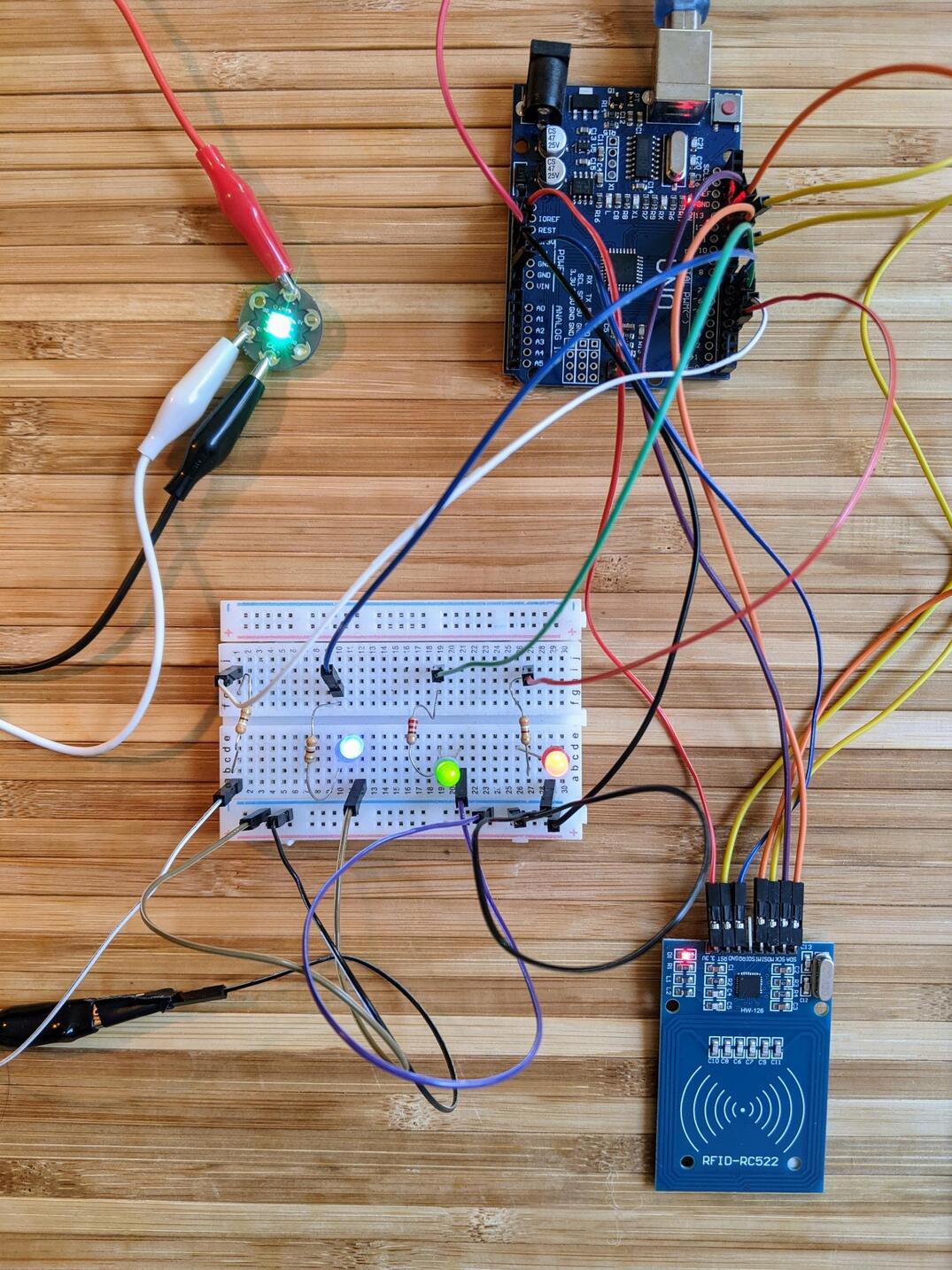
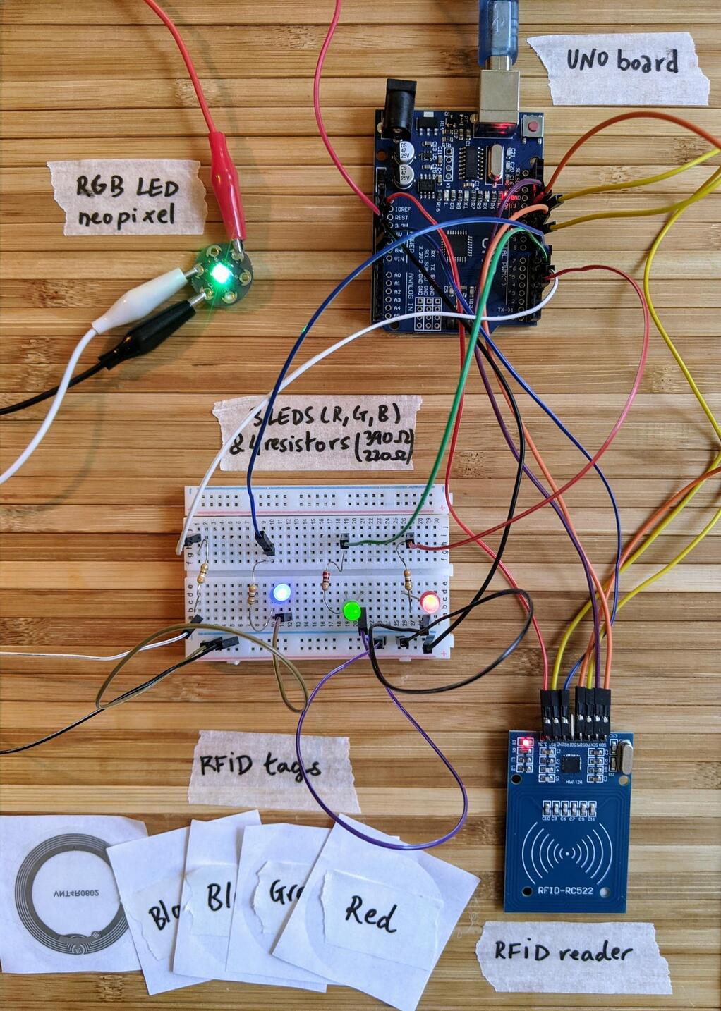
One of the solution I thought about was using a RFID reader and RFID passive tags. I had used some in the past, with not always success, but at least I had the components at home!
Components and connections
So I dug again the documentation of these RC522 RFID readers. They apparently can be used both with SPI or I2C. I went for SPI as I already used it last time, but maybe I should also try other protocols during the communication week. These readers work with 3.3 V so you need to connect them to the 3.3V pin, or use a level shifter if you're designing your own board and it's powered with 5V.
They need a lot of PINs to work!
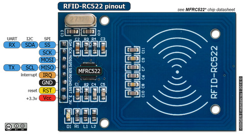
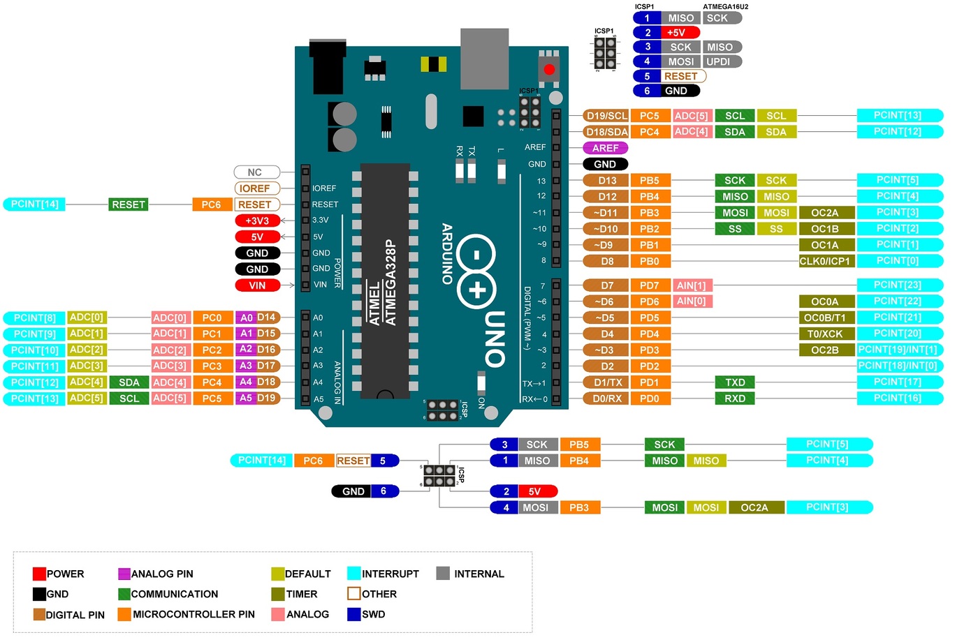
Here's also the Arduino UNO Pinout Diagram:
I also had RFID passive tags: one blue badge and several transparent stickers.
Libraries
I used the MFRC522 library of miguelbalboa, which is in freeze mode, that is very low maintenance and no further developement. Why this one? Because I used it in the past and it was okay, but I may switch to another library if I carry on with these RFID readers, and depeding on the MCU family I use. I also have to admit I could'nt make it work with my D1 mini so I used a regular Arduino UNO. It relies on SPI protocol so you also have to include the SPI.h library. For that one you don't need to install anything new, it usually comes with the board manager packages.
Connections depends from the board you’re using.
| ESP8266 | UNO | |
|---|---|---|
| Wemos D1 mini | ||
| Signal | Pin | Pin |
| RST/Reset | D3 | 9 |
| SPI SS | D8 | 10 |
| SPI MOSI | D7 | 11 |
| SPI MISO | D6 | 12 |
| SPI SCK | D5 | 13 |
Read the UID of passive tags
I used the DumpInfo.ino example which comes up with the rfid library to read the UID of my various passive tags in the serial monitor. The UID is a unique identifier, a sort of 'address' of the tags. I could also read other info of my tags, but UID is the one that interests me the most since I use conditions to trigger various actions depending on which tag is presented to the reader.
I had nothing to change to the example to read the UID, except the pins at the beginning of the sketch that vary depending of your board. Don't forget to adapt them too:
#define RST_PIN         9          // Configurable, see typical pin layout above
#define SS_PIN          10         // Configurable, see typical pin layout above
I had two types of tags: one blue badge and several stickers
This is when I read the blue badge:
Firmware Version: 0x92 = v2.0
Scan PICC to see UID, SAK, type, Firmware Version: 0x92 = v2.0
Scan PICC to see UID, SAK, type, and data blocks...
**Card UID: 9A 2B 98 15**
Card SAK: 08
PICC type: MIFARE 1KB
Sector Block   0  1  2  3   4  5  6  7   8  9 10 11  12 13 14 15  AccessBits
  15     63   00 00 00 00  00 00 FF 07  80 69 FF FF  FF FF FF FF  [ 0 0 1 ]
         62   00 00 00 00  00 00 00 00  00 00 00 00  00 00 00 00  [ 0 0 0 ]
         61   00 00 00 00  00 00 00 00  00 00 00 00  00 00 00 00  [ 0 0 0 ]
         60   00 00 00 00  00 00 00 00  00 00 00 00  00 00 00 00  [ 0 0 0 ]
  14     59   00 00 00 00  00 00 FF 07  80 69 FF FF  FF FF FF FF  [ 0 0 1 ]
         58   00 00 00 00  00 00 00 00  00 00 00 00  00 00 00 00  [ 0 0 0 ]
         57   00 00 00 00  00 00 00 00  00 00 00 00  00 00 00 00  [ 0 0 0 ]
         56   00 00 00 00  00 00 00 00  00 00 00 00  00 00 00 00  [ 0 0 0 ]
  13     55   00 00 00 00  00 00 FF 07  80 69 FF FF  FF FF FF FF  [ 0 0 1 ]
         54   00 00 00 00  00 00 00 00  00 00 00 00  00 00 00 00  [ 0 0 0 ]
         53   00 00 00 00  00 00 00 00  00 00 00 00  00 00 00 00  [ 0 0 0 ]
         52   00 00 00 00  00 00 00 00  00 00 00 00  00 00 00 00  [ 0 0 0 ]
  12     51   00 00 00 00  00 00 FF 07  80 69 FF FF  FF FF FF FF  [ 0 0 1 ]
         50   00 00 00 00  00 00 00 00  00 00 00 00  00 00 00 00  [ 0 0 0 ]
         49   00 00 00 00  00 00 00 00  00 00 00 00  00 00 00 00  [ 0 0 0 ]
         48   00 00 00 00  00 00 00 00  00 00 00 00  00 00 00 00  [ 0 0 0 ]
  11     47   00 00 00 00  00 00 FF 07  80 69 FF FF  FF FF FF FF  [ 0 0 1 ]
         46   00 00 00 00  00 00 00 00  00 00 00 00  00 00 00 00  [ 0 0 0 ]
         45   00 00 00 00  00 00 00 00  00 00 00 00  00 00 00 00  [ 0 0 0 ]
         44   00 00 00 00  00 00 00 00  00 00 00 00  00 00 00 00  [ 0 0 0 ]
  10     43   00 00 00 00  00 00 FF 07  80 69 FF FF  FF FF FF FF  [ 0 0 1 ]
         42   00 00 00 00  00 00 00 00  00 00 00 00  00 00 00 00  [ 0 0 0 ]
         41   00 00 00 00  00 00 00 00  00 00 00 00  00 00 00 00  [ 0 0 0 ]
         40   00 00 00 00  00 00 00 00  00 00 00 00  00 00 00 00  [ 0 0 0 ]
   9     39   00 00 00 00  00 00 FF 07  80 69 FF FF  FF FF FF FF  [ 0 0 1 ]
         38   00 00 00 00  00 00 00 00  00 00 00 00  00 00 00 00  [ 0 0 0 ]
         37   00 00 00 00  00 00 00 00  00 00 00 00  00 00 00 00  [ 0 0 0 ]
The stickers return less values, here are 3 examples :
Card UID: 04 FB 32 22 DA 64 80
Card SAK: 00
PICC type: MIFARE Ultralight or Ultralight C
Page  0  1  2  3
  0   04 FB 32 45
  1   22 DA 64 80
  2   1C 48 00 00
  3   E1 10 3E 00
  4   03 00 FE 00
  5   00 00 00 00
  6   00 00 00 00
  7   00 00 00 00
Card UID: 04 F3 30 22 DA 64 80
Card SAK: 00
PICC type: MIFARE Ultralight or Ultralight C
Page  0  1  2  3
  0   04 F3 30 4F
  1   22 DA 64 80
  2   1C 48 00 00
  3   E1 10 3E 00
Card UID: 04 02 34 22 DA 64 81
Card SAK: 00
PICC type: MIFARE Ultralight or Ultralight C
Page  0  1  2  3
  0   04 02 34 BA
  1   22 DA 64 81
  2   1D 48 00 00
  3   E1 10 3E 00
  4   03 00 FE 00
  5   00 00 00 0
  6   00 00 00 00
  7   00 00 00 00
In all the case it is the first row of the matrix that interests me. For now I will start with 5 sticker tags. Here are their adress and how i named them:
| Name | Card UID |
|---|---|
| Red | 04 FB 32 22 DA 64 80 |
| Green | 04 F3 30 22 DA 64 80 |
| Blue | 04 87 31 22 DA 64 80 |
| White | 04 96 31 22 DA 64 80 |
| Black | 04 02 34 22 DA 64 81 |
Trigger actions depending on the tag presented
The provided example allow us to use several RC522 readers, while it could cause some trouble as we're using SPI protocol. I set values to use only one reader.
I then adapted the example to trigger actions. As in my serial examples, I wanted to change the brightness of the three LEDs and the (R,G,B) color of the Neopixel.
The logic is a bit different and closer to what I want to do in my final project, which is not entering a fixed value but increment it with a given tag. So here I will increment r, g and b variables from 10 to 10 (max is 255, min is 0).
Also I added a black tag which decreases the neopixel's brightness by 20 (max is 255, min is 0), and a white tag which turns all LEDs off and reset all values.
/**

 * --------------------------------------------------------------------------------------------------------------------
 * Example sketch/program showing how to read data from more than one PICC to serial.
 * --------------------------------------------------------------------------------------------------------------------
 * This is a MFRC522 library example; for further details and other examples see: https://github.com/miguelbalboa/rfid
 *
 * Example sketch/program showing how to read data from more than one PICC (that is: a RFID Tag or Card) using a
 * MFRC522 based RFID Reader on the Arduino SPI interface.
 *
 * Warning: This may not work! Multiple devices at one SPI are difficult and cause many trouble!! Engineering skill
 *          and knowledge are required!
 *
 * @license Released into the public domain.
 *
 * Typical pin layout used:
 * -----------------------------------------------------------------------------------------
 *             MFRC522      Arduino       Arduino   Arduino    Arduino          Arduino
 *             Reader/PCD   Uno/101       Mega      Nano v3    Leonardo/Micro   Pro Micro
 * Signal      Pin          Pin           Pin       Pin        Pin              Pin
 * -----------------------------------------------------------------------------------------
 * RST/Reset   RST          9             5         D9         RESET/ICSP-5     RST
 * SPI SS 1    SDA(SS)      ** custom, take a unused pin, only HIGH/LOW required **
 * SPI SS 2    SDA(SS)      ** custom, take a unused pin, only HIGH/LOW required **
 * SPI MOSI    MOSI         11 / ICSP-4   51        D11        ICSP-4           16
 * SPI MISO    MISO         12 / ICSP-1   50        D12        ICSP-1           14
 * SPI SCK     SCK          13 / ICSP-3   52        D13        ICSP-3           15
 *
 */

#include <SPI.h>
#include <MFRC522.h>
#include <Adafruit_NeoPixel.h>

#define LED_R 3
#define LED_G 5
#define LED_B 6
#define PIX 4
#define NUMPIXELS 1 //number of neopixels


Adafruit_NeoPixel pixels(NUMPIXELS, PIX, NEO_GRB + NEO_KHZ800);

int del = 50;  //delay
int r = 0;
int g = 0;
int b = 0;
int w = 0;
int k = 200;

#define RST_PIN 9          // Configurable, see typical pin layout above
#define SS_1_PIN 10        // Configurable, take a unused pin, only HIGH/LOW required, must be diffrent to SS 2
//#define SS_2_PIN 49          // Configurable, take a unused pin, only HIGH/LOW required, must be diffrent to SS 1

#define NR_OF_READERS 1

byte ssPins[] = {SS_1_PIN};

MFRC522 mfrc522[NR_OF_READERS];   // Create MFRC522 instance.


/**
 * Initialize.
 */
void setup() {
  pinMode(LED_R, OUTPUT);
  pinMode(LED_G, OUTPUT);
  pinMode(LED_B, OUTPUT);
  pinMode(PIX, OUTPUT);

// pixels.begin();
// pixels.clear();

  digitalWrite(LED_R, LOW);
  digitalWrite(LED_G, LOW);
  digitalWrite(LED_B, LOW);

  Serial.begin(9600); // Initialize serial communications with the PC
  while (!Serial);    // Do nothing if no serial port is opened (added for Arduinos based on ATMEGA32U4)

  SPI.begin();        // Init SPI bus

  for (uint8_t reader = 0; reader < NR_OF_READERS; reader++) {
    mfrc522[reader].PCD_Init(ssPins[reader], RST_PIN); // Init each MFRC522 card

  }
}

/**
 * Main loop.
 */
void loop() {

  for (uint8_t reader = 0; reader < NR_OF_READERS; reader++) {
    // Look for new cards
    // String content[reader];

    if (mfrc522[reader].PICC_IsNewCardPresent() && mfrc522[reader].PICC_ReadCardSerial()) {

      Serial.print(F("Reader "));
      Serial.print(reader);
      // Show some details of the PICC (that is: the tag/card)
      Serial.print(F(": Card UID:"));
      Serial.println();

      readTags(mfrc522[reader].uid.uidByte, mfrc522[reader].uid.size);

    }

      // Halt PICC
      mfrc522[reader].PICC_HaltA();
      // Stop encryption on PCD
      mfrc522[reader].PCD_StopCrypto1();

  } //fin de la boucle avec les reader
}

/**
 * Helper routine to dump a byte array as hex values to Serial.
 */
void readTags(byte *buffer, byte bufferSize) {

  String adress="";

  for (byte i = 0; i < bufferSize; i++) {
    Serial.print(buffer[i] < 0x10 ? " 0" : " ");
    Serial.print(buffer[i], HEX);
    adress.concat(String(buffer[i] < 0x10 ? " 0" : " "));
    adress.concat(String(buffer[i], HEX));

  }

  adress.toUpperCase();

  if (adress.substring(1) == "04 FB 32 22 DA 64 80")
  {
    r += 10;
    Serial.print(F(" red tag identified"));
    // String wrapper for printing strings in the serial monitor and using Flash memory instead of SRAM
    analogWrite(LED_R, r);
    pixels.setPixelColor(0, pixels.Color(r,g,b)); //starts at 0!
    pixels.setBrightness(k);
    pixels.show();
    Serial.println();
    Serial.println("Value of red color is " + String(r));
    delay(del);
  }


else if (adress.substring(1) == "04 F3 30 22 DA 64 80")
  {
    g += 10;
    Serial.print(F(" green tag identified"));
    delay(del);
    Serial.println();
    analogWrite(LED_G, g);
    pixels.setPixelColor(0, pixels.Color(r,g,b)); //starts at 0!
    pixels.setBrightness(k);
    pixels.show();
    Serial.println();
    Serial.println("Value of green color is " + String(g));
    delay(del);

  }


 else if (adress.substring(1) == "04 87 31 22 DA 64 80")
  {
    b += 10;
    Serial.print(F(" blue tag identified"));
    delay(del);
    Serial.println();
    analogWrite(LED_B, b);
    pixels.setPixelColor(0, pixels.Color(r,g,b)); //starts at 0!
    pixels.setBrightness(k);
    pixels.show();
    Serial.println();
    Serial.println("Value of blue color is " + String(b));

  }

 else if (adress.substring(1) == "04 96 31 22 DA 64 80")
  {
    Serial.print(F(" white tag identified"));
    delay(del);
    Serial.println();
    digitalWrite(LED_R, LOW);
    digitalWrite(LED_G, LOW);
    digitalWrite(LED_B, LOW);
    r=0;
    g=0;
    b=0;
    k = 200;
    pixels.setPixelColor(0, pixels.Color(r,g,b)); //starts at 0!
    pixels.setBrightness(k);
    pixels.show();

  }

   else if (adress.substring(1) == "04 02 34 22 DA 64 81")
  {
    Serial.print(F(" black tag identified"));
    k -= 20;
    Serial.println();
    Serial.println("Value of brightness is " + String(k));
    delay(del);
    Serial.println();
    pixels.setBrightness(k);
    pixels.setPixelColor(0, pixels.Color(r,g,b)); //starts at 0!
    pixels.show();
  }

else
  {
    Serial.print("unknown tag");
    delay(500);
  }

}
More hero shots and videos 8-) It's unfortunately a bit hard to really see on the video the color changing of the neopixel. Come to the lab to see them in real life.
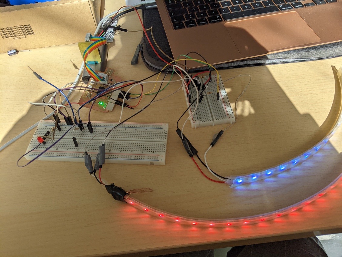
Week 9 - Output Devices
Week's explorations and achievments
- Test several output devices (breadbord connections):
- RGBW led strips
- Servomotor
- DC motor
- LCD screen
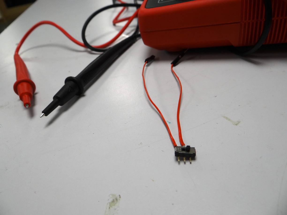
- Test electrical circuits and gesture workflows for the final project
- Sketch new ideas for the final project
- Design, produce and test small boards for the final project
- Led element: data input part
- Led element: contact pads for data input and ground
- Led element: battery part
- Microcontroller side: contact pads for trigger and data GPIOs and ground
- Unfortunately we didn't have the opportunity to do the group assignment
Output devices tests
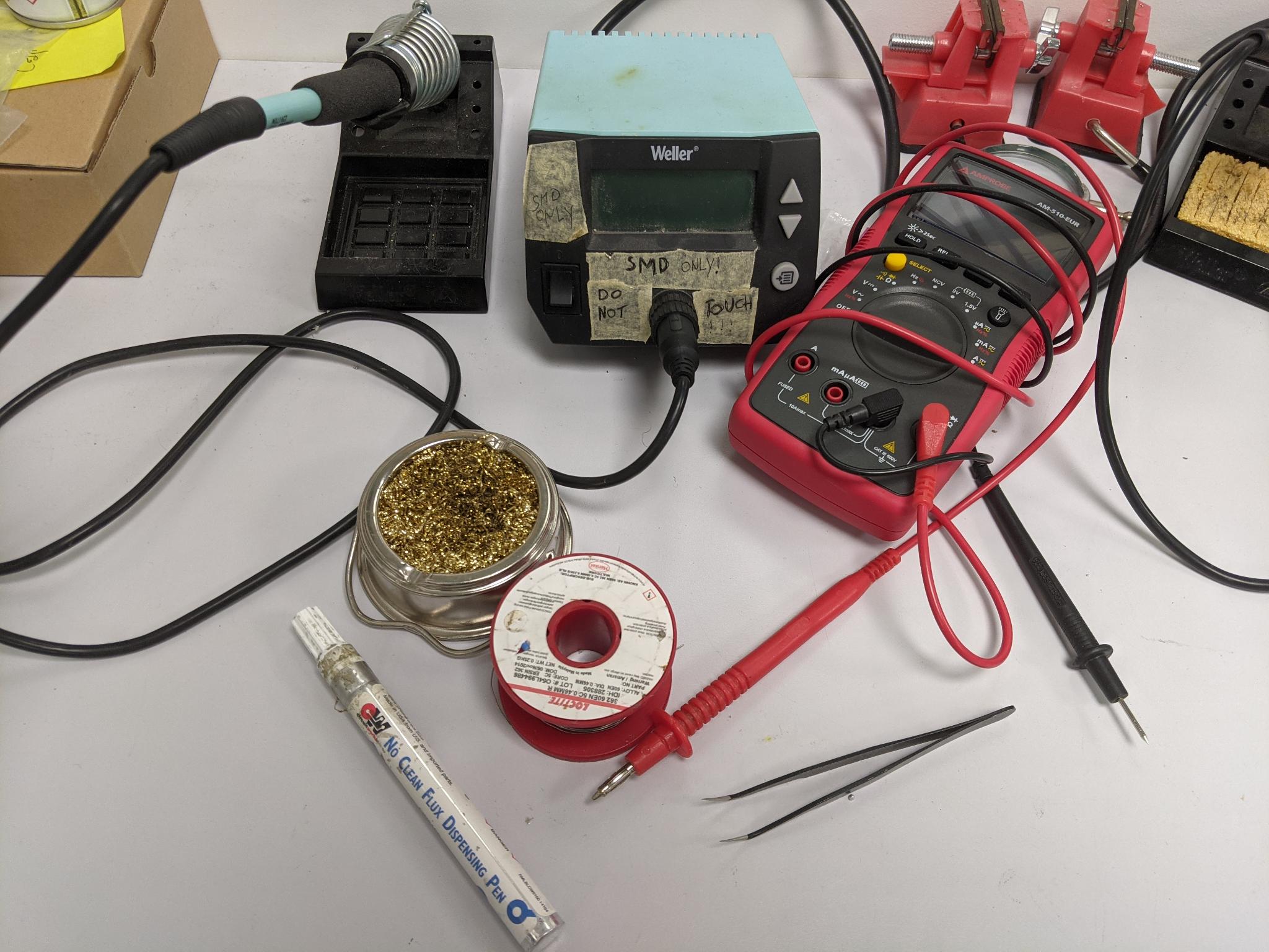
Since there are strikes ongoing in France, it affects my ability to come and work in the lab (closed campus, public transportation issues), so I worked with components I could find at home.
RGB Leds
Built-in WS2812B leds
I used the last board designed and produced during the electronic production week. It provides an ATtiny3216, SPI and I2C, a bunch of GPIOs and WS2812B RGB leds. I thus attempted to program them at first, but they didn't light up. At first I thought maybe there was a problem of compatibility with the libraries and invested this question. But since nothing happened at all I realised it is probably a hardware problem, most likely bad soldering. Indeed, their pads are under the element and it's then quite complicated to solder them manually. My instructor had adviced me the week before to solder them with solder paste and a refusion oven, but since he's not there this week I just carried on with external led strips.
Neopixel strips recommmandations
I used leds strips I had at home that I used in a previous small personal project. I don't have the exact reference but they are Neopixel alike led strips.
Here are the best practices provided by Adafruit's in their [Neopixel Uberguide] (https://learn.adafruit.com/adafruit-neopixel-uberguide/best-practices) that I follow when I do a project with led strips:
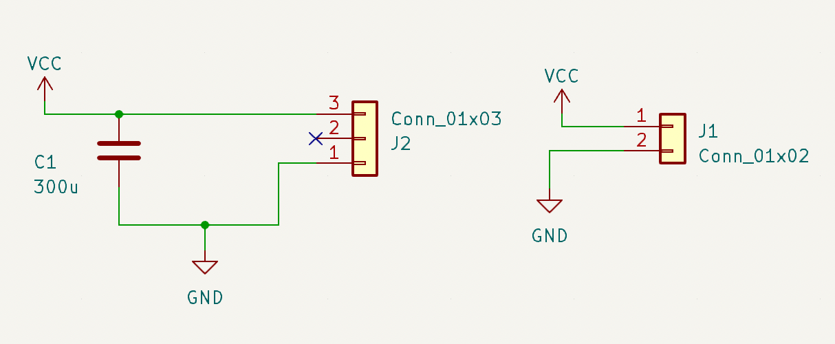
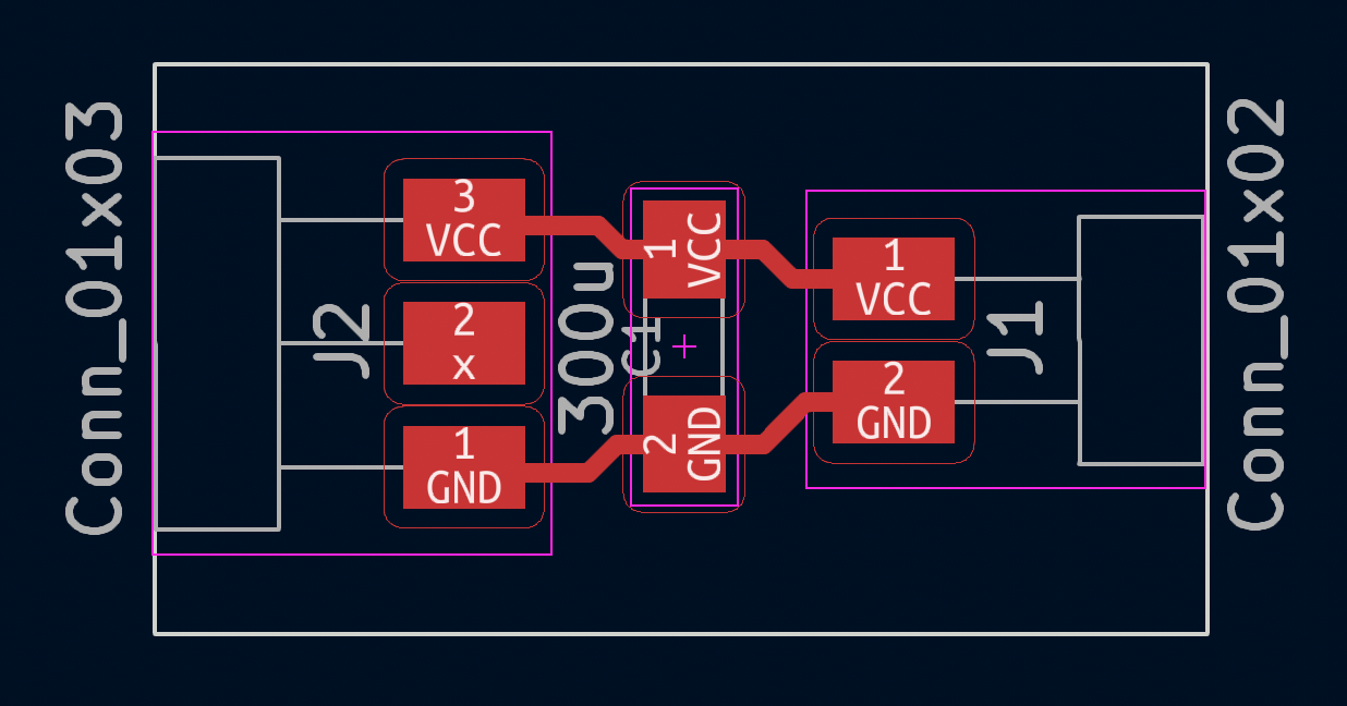
Before connecting NeoPixels to any large power source (DC “wall wart” or even a large battery), add a capacitor (500–1000 µF at 6.3V or higher) across the + and – terminals as shown above. The capacitor buffers sudden changes in the current drawn by the strip.
[Comment: in fact I tend to add a capacitor even when I don't have a particularly large battery, since I observed it could improve the stability of the led's light]
Place a 300 to 500 Ohm resistor between the Arduino data output pin and the input to the first NeoPixel. The resistor should be at the end of the wire closest to the NeoPixel(s), not the microcontroller. Some products already incorporate this resistor…if you’re not sure, add one…there’s no harm in doubling up! Also, newer NeoPixels are less picky about this. Nothing’s needed at the “out” end of a strip…you can leave the data out “floating.”
[Comment: I systematically added a 300 Ohm resistor between the microcontroller data output and the input to the first led of the strip]
Try to minimize the distance between the Arduino and first pixel, so the signal is clear. A meter or two is usually no problem. Much longer and things can become unreliable. Individual NeoPixels can act as repeaters for long runs.
[Comment: I will not be concerned by this issue in this project]
Avoid connecting NeoPixels to a live circuit. If you simply must, always connect ground first, then +5V, then data. Disconnect in the reverse order.
[Comment: I don't think my project respects that point, but I'm not sure what are the risks here]
If powering the pixels with a separate supply, apply power to the pixels before applying power to the microcontroller. Otherwise they’ll try to power “parasitically” through the data line, which could spell trouble for the microcontroller.
Observe the same precautions as you would for any static-sensitive part; ground yourself before handling, etc.
NeoPixels powered by 5v ideally need a 5V data signal. If using a 3.3V microcontroller you must use a logic level shifter such as a 74AHCT125 or 74HCT245. See the “Logic Level Shifting” page for more details. If you are powering your NeoPixels with 3.7v directly from a LiPoly cell, a 3.3v data signal is OK.
[Comment: The ATtiny3216 provides 5V so I believe I don't have to worry about that? Also not sure if all my strips will be powered the same way, some might be by 5V, others with 3.7V LiPoly cell, not sure if it's a problem?]
If your microcontroller and NeoPixels are powered from two different sources (e.g. separate batteries for each), there must be a ground connection between the two.
[Comment: This is important to take in account in my circuits design]
Make sure that your connections are secure. Alligator clips do not make reliable connections to the tiny solder pads on NeoPixel rings. Better to solder a small pigtail wire to the ring and attach the alligator clips to that.
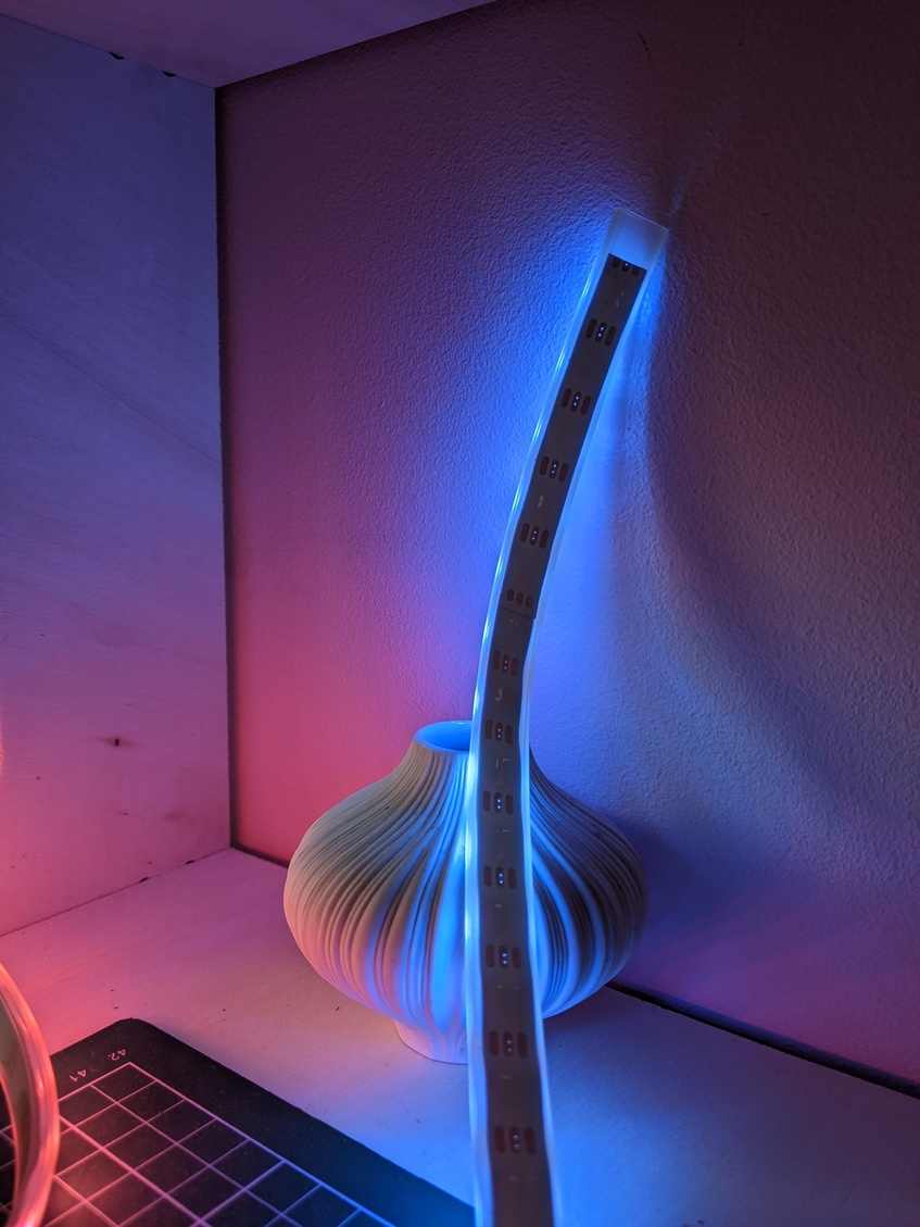
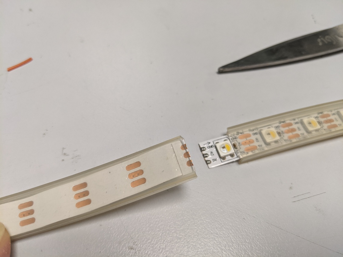
Tests with led strips
Following the recommandations I added a 470 uF capacitor between the VCC and GND pin of the neopixel strip and a 300 Ohm resistor on the data line. For these tests I used the same power source for the led strip than for the microcontroller (5V USB). I connected the data line to the PIN 5 (my GPIO6).
I used to work with the Adafruit Neopixel library and also used it during the Embedded Programming week with the ATtiny1614 and other commercial boards, so I used it for mmy first tests. But what worried me after the very first test was that the colors were completely inconsistent. For example I asked for green in the programm and obtained different leds color.
I thought that maybe the library was not compatible with the ATtiny3216 which has a slightly different architecture than the ATtiny1614 (it's a megaavr architecture) and looked for other libraries. I read that some other person struggled also with led libraries issues with this microcontroller so I went for the tinyNeopixel.h library. It provides both a static and a non static version. I first tried the static version with the simple example
Here's how to define a strip object using the tinyNeopixel library. NUMPIXELS is the number of pixels, PIN the data pin, and the third parameter NEO_GRB is the pixel type flags :
// NEO_GRB Pixels are wired for GRB bitstream (most NeoPixel products)
// NEO_RGB Pixels are wired for RGB bitstream (v1 FLORA pixels, not v2)
So I first declared my strip that way.
Then thought it might be a problem of color bitstream
It wasn't any better. Than I remembered that a long time ago I faced such issue and it was a problem of white led or white color encoding. I thus switched my declaration for:
Almost there! The correct declaration was indeed:
But obviously there was still a small issues to fix, as some pixels were incorrect.
I switched for the non-static version of tinyNeopixel.h, and everything went as expected. Not sure why though! I also tested the strandtest example and everything went smoothly.
Two strips tests
I added a second strip on PIN 4 (my GPIO5). I added a resistor but no other capacitor since all were connected together and very physically close.
Here's the code, adapted from the simple test example.
// NeoPixel Ring simple sketch (c) 2013 Shae Erisson
// released under the GPLv3 license to match the rest of the AdaFruit NeoPixel library

#include <tinyNeoPixel.h>

// Which STRIP_A on the Arduino is connected to the NeoPixels?
#define STRIP_A           5
#define STRIP_B 4

// How many NeoPixels are attached to the Arduino?
#define NUMPIXELS_A      16
#define NUMPIXELS_B      16

// When we setup the NeoPixel library, we tell it how many pixels, and which PIN to use to send signals.
// Note that for older NeoPixel strips you might need to change the third parameter--see the strandtest
// example for more information on possible values.
tinyNeoPixel pixels_a = tinyNeoPixel(NUMPIXELS_A, STRIP_A, NEO_GRBW + NEO_KHZ800);
tinyNeoPixel pixels_b = tinyNeoPixel(NUMPIXELS_B, STRIP_B, NEO_GRBW + NEO_KHZ800);
int delayval = 50;
int r= 200;
int g=20;
int b = 10;

int r2= 0;
int g2= 60;
int b2= 200;

void setup() {

  pixels_a.begin(); // This initializes the NeoPixel library.
  pixels_b.begin(); // This initializes the NeoPixel library.
}

void loop() {

  // For a set of NeoPixels the first NeoPixel is 0, second is 1, all the way up to the count of pixels minus one.

  for (int i = 0; i < NUMPIXELS_A; i++) {
    // pixels.Color takes RGB values, from 0,0,0 up to 255,255,255
    pixels_a.setPixelColor(i, pixels_a.Color(r, g, b)); // Moderately bright green color.
    pixels_a.show(); // This sends the updated pixel color to the hardware.
    delay(delayval); // Delay for a period of time (in milliseconds).
  }

  for (int i = 0; i < NUMPIXELS_B; i++) {
    // pixels.Color takes RGB values, from 0,0,0 up to 255,255,255
    pixels_b.setPixelColor(i, pixels_b.Color(r2, g2, b2)); // Moderately bright green color.
    pixels_b.show(); // This sends the updated pixel color to the hardware.
    delay(delayval); // Delay for a period of time (in milliseconds).
  }

}
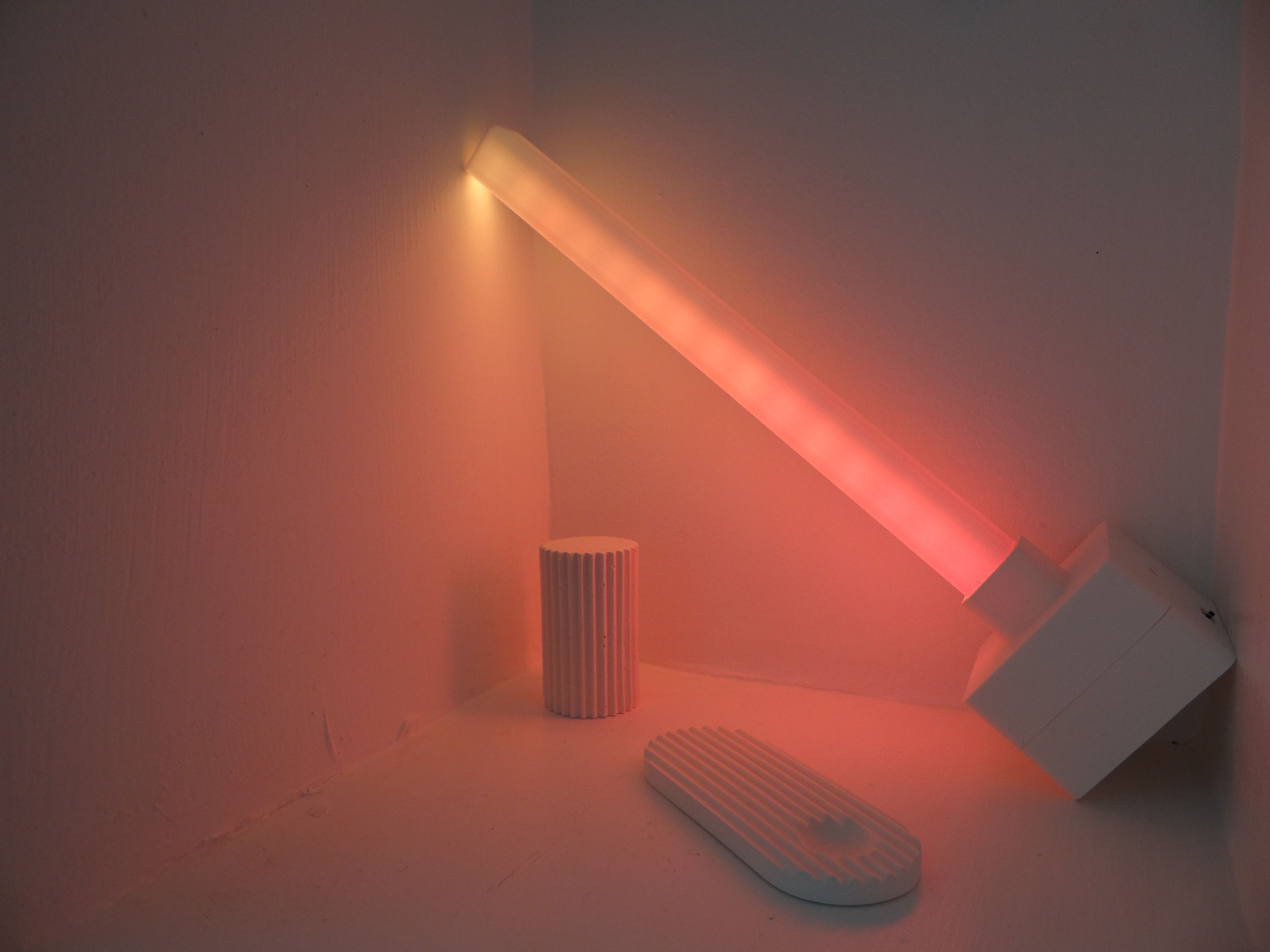
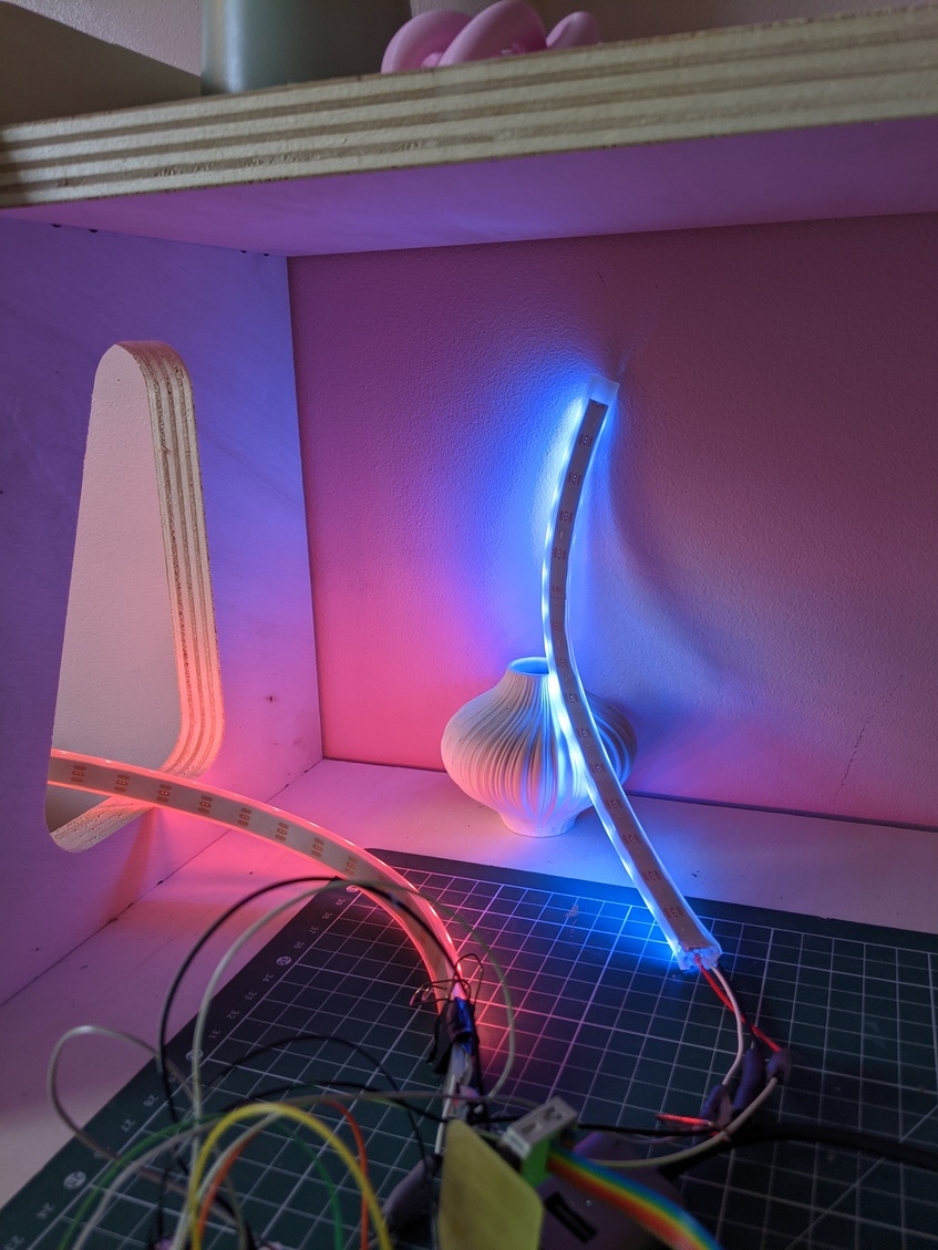
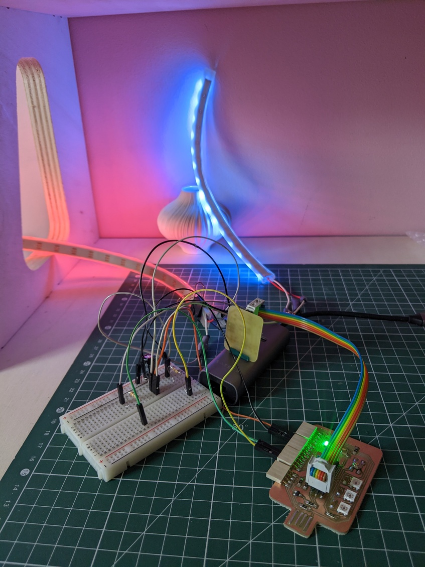
I wanted to test how I could play with led lighting for my final project. I was enchanted by the results of these very first tests, even in daylight the light is strongh enough to make beautiful effects. I used a white ceramic vase with nice creases to see the variations in the lighting and the color of shadows and I am willing to experiment more with such "obstacles" (as described in my first final project sketches). Also I enjoyed how the roughness of the wall interacts with the light, as it was something I initially wanted to experiment too (see "textures" in my first sketches). I think that the shadows are great and the way the colored lights blends towards a yellowish light is really nice.
Sketches and useflow exploration for the final project
A small reminder of the initial idea of my final project:
I gave it more thought, adding the possibility to have a type of element powered by the same supply as the microcontroller, or at least less independent power supplies.
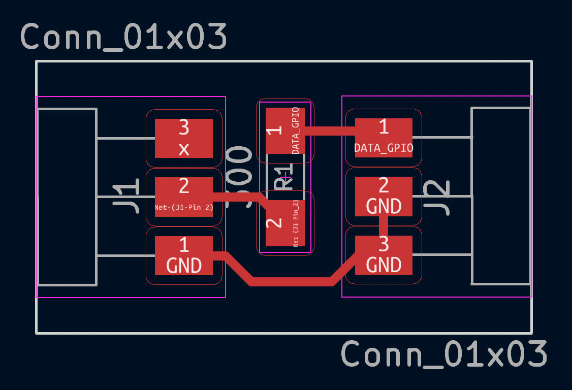
In this sketch I close the data line which sends the color instruction to the neopixel, as in the following video:
It works but I also wanted to detect the contact to be able to increment a time delay from the moment the contact is made. I got inspired by this resource on electronicwings.com to do a simple input pullup on one of the GPIO.
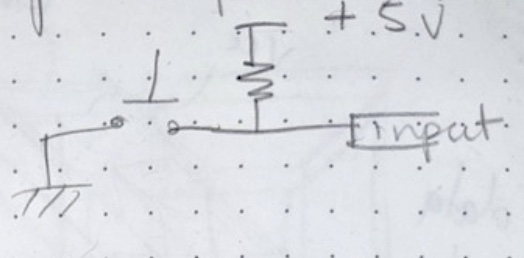
Thus the following code allows me to turn on a led when I close the circuit connected to the GPIO 4 (PIN 3 in arduino). Note that there when the circuit is opened the input pin is connected through a pull up resistor to 5V, and when you close the circuit it's connected to the ground. For this reason the condition you'll use in your code is (trigState==0) to detect the moment when the circuit is closed.
#define TRIG 3
#define LED 4

void setup() {
pinMode(TRIG, INPUT_PULLUP);
pinMode(LED, OUTPUT);
}

void loop() {

  int trigState = digitalRead(TRIG);

 if (trigState==0){
  digitalWrite(LED, HIGH); //turn len on when switch pressed
 }

 else {
  digitalWrite(LED, LOW); //turn len on when switch pressed
 }

  delay(1);

}
After I suceeded with a simple LED (and a 300 Ohm resistor to protect it), I used this input to trigger the progressvie lighting of the neopixels.
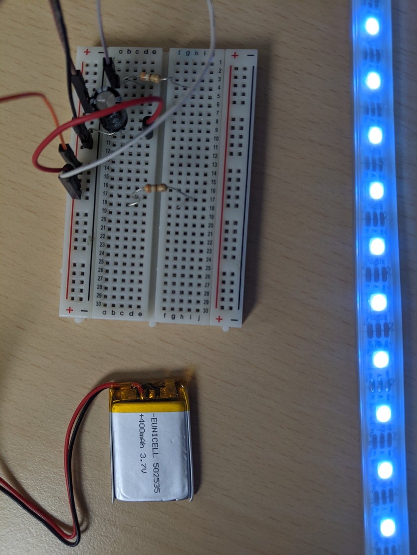
I also did test powering the led strip with a 3.7V LiPo Cell battery. Always be careful to still connect the grounds of the two circuits together!
Small test boards for the final project
Design
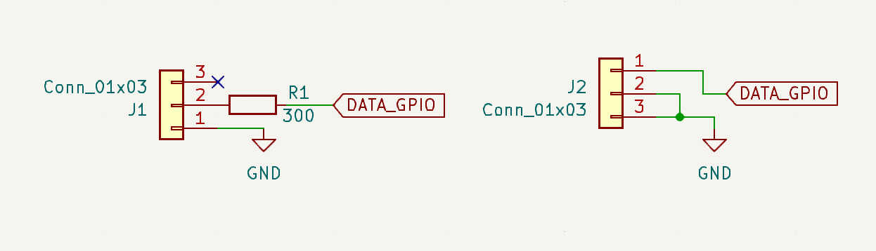
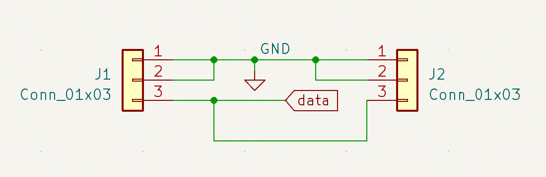
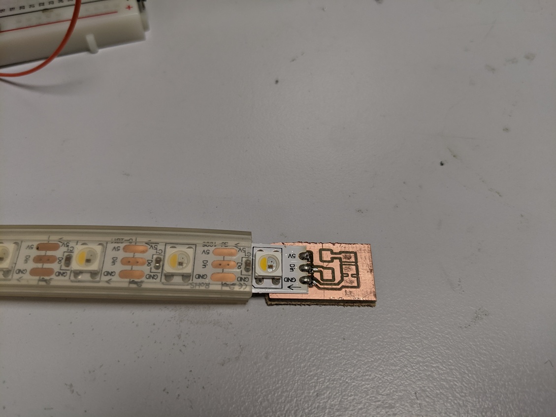
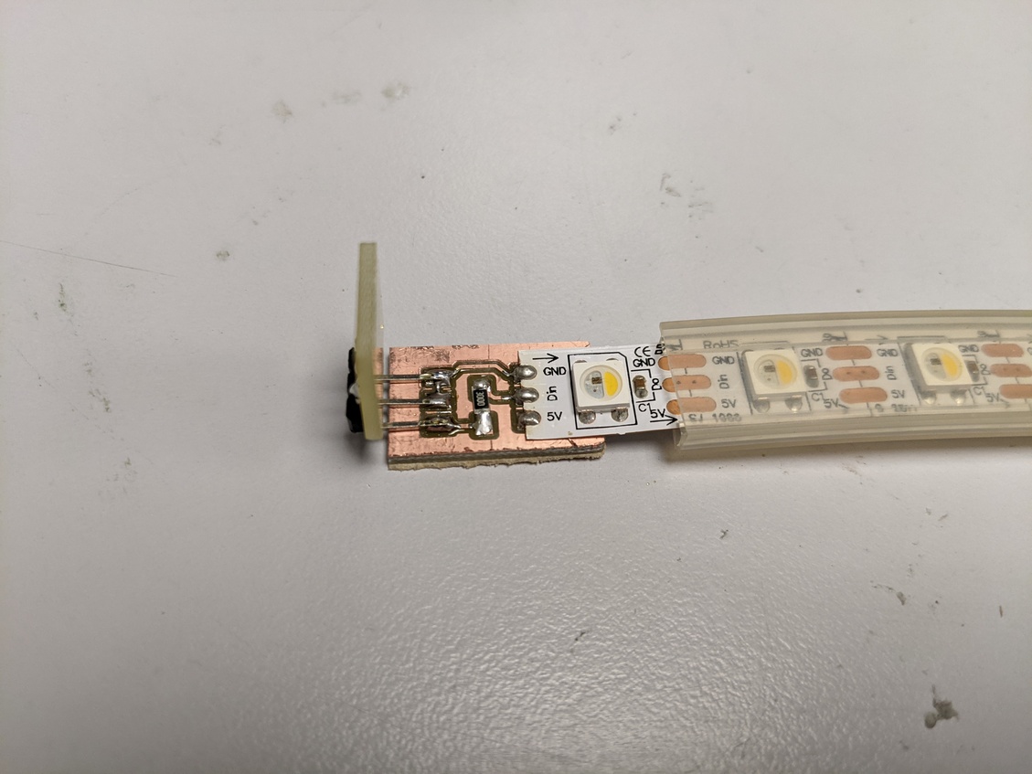
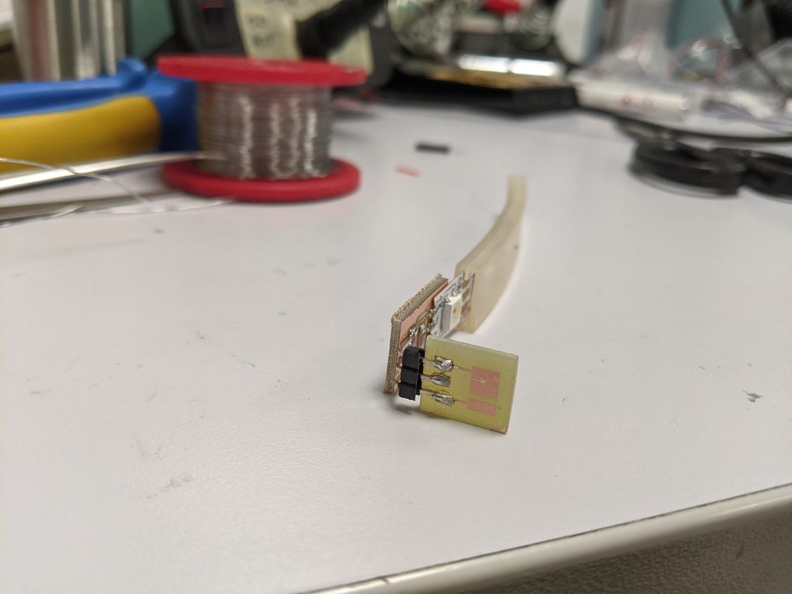
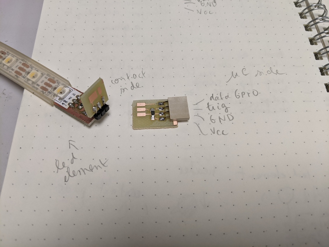
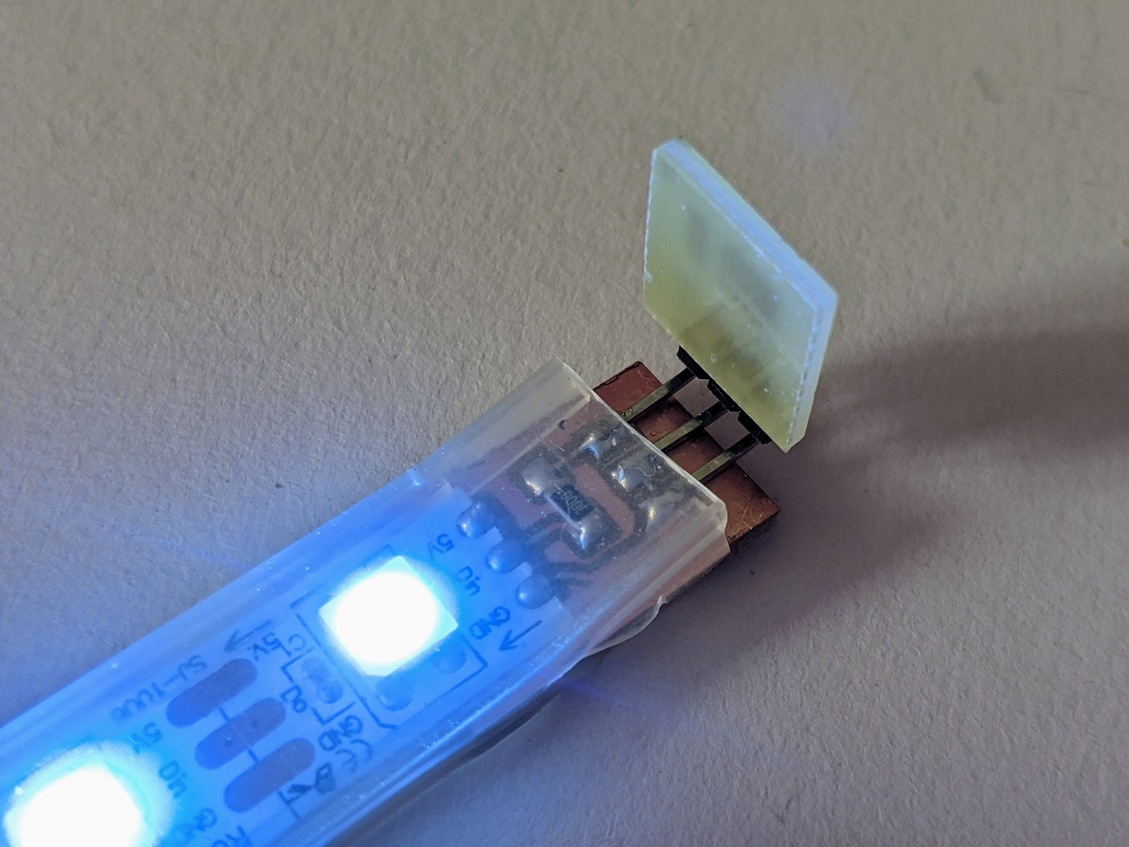
I used the trigger tests I did earlier to design small contact pads and minimal boards to ensure connections, add the small components (pull up resistor, resistor on the data line for the neopixel strip, capacitor between Vcc and ground for the neopixel strip) and header pins. Here is a sort of general principle of what I need on the two sides of my opened circuit, that are the microcontroller side and the movable led element side:
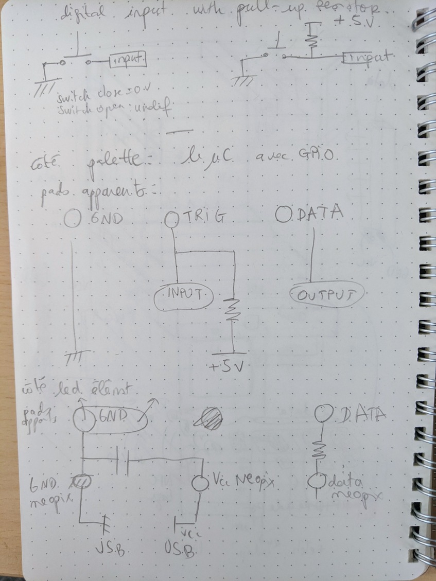
The led element can be powered independetly with a battery (I did tests wit a 3.7V LipoCell battery) or with the same Vcc and GND line if it makes contact in the enclosure (see sketch in the previous section).
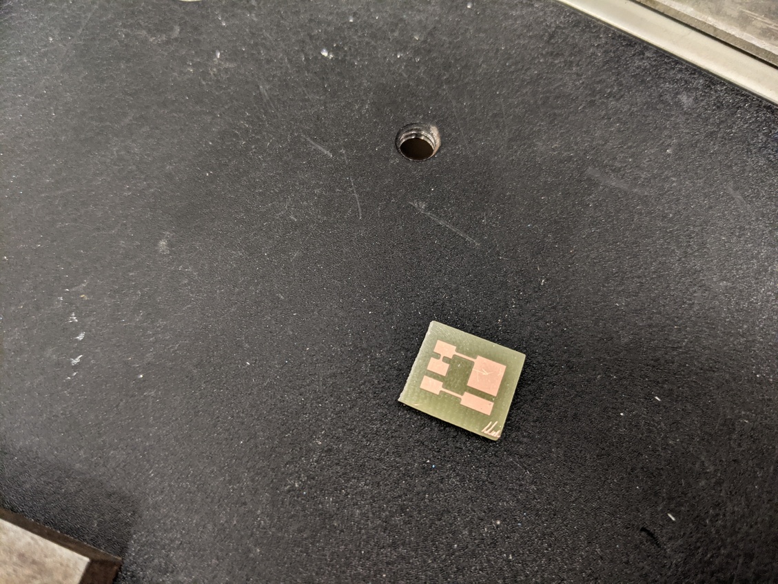
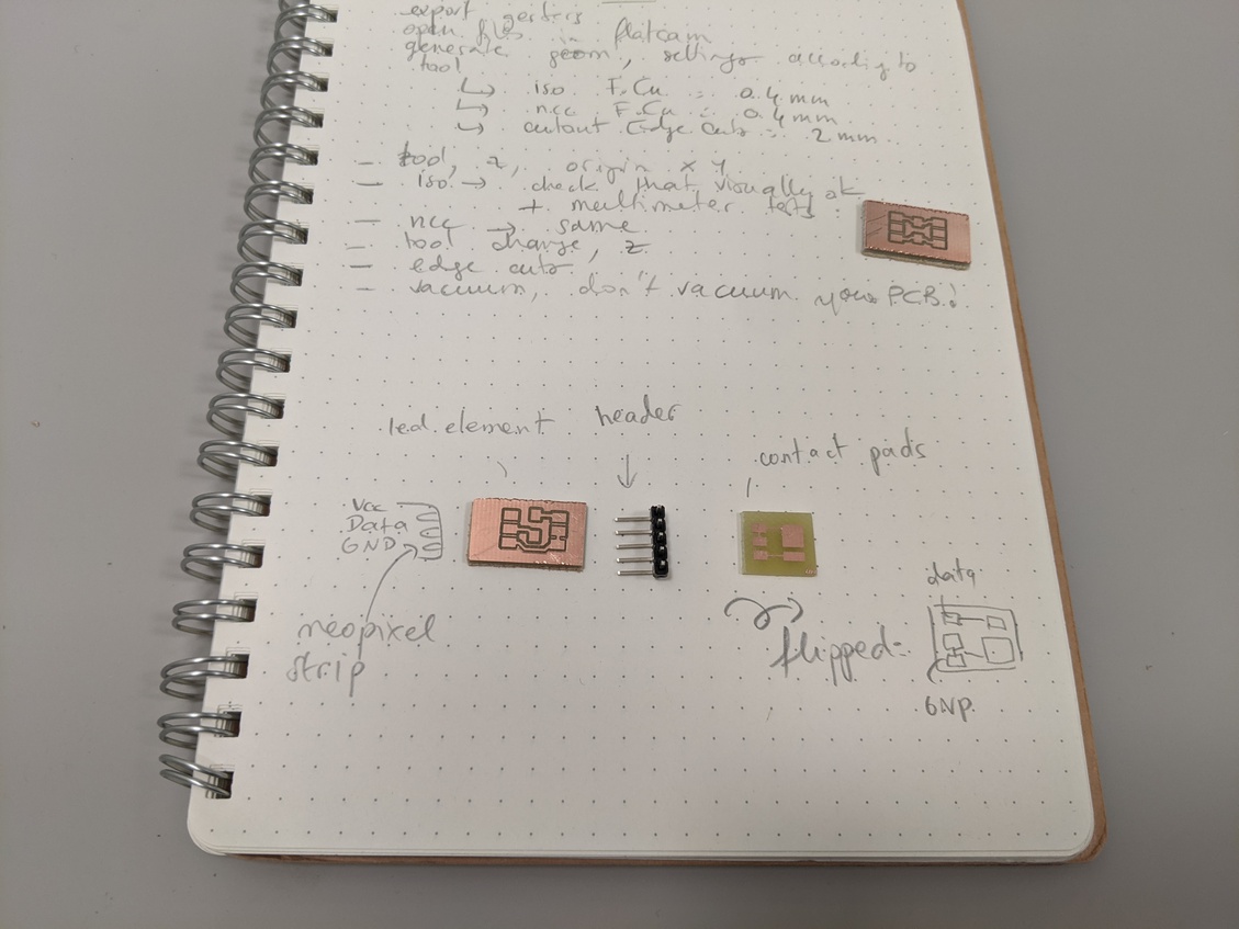
I thus designed four very small boards:
- Led element: data input part
- Led element: contact pads for data input and ground
- Led element: battery part
- Microcontroller side: contact pads for trigger and data GPIOs and ground
Led element unit - data input
This is the last version. In the first version I draw both this board and the battery part on the same schematic and PCB. They are now divided in two seperate files.
Led element - Battery
This is the second version, the first one provided a 3 header pin which was not convenient for connecting the LiPo cell battery.
Led element - Contact pads for data input and ground
This PCB will be connected to the first one with angled header pins.
Microcontroller side - Contact pads and GPIOs

Mill
Here are the tools and settings I used:
- 0.4mm cylindric mill for the tracks, 2 passes with 40% overlap, -0.05mm depth, 90mm/s X/Y speed and 80mm/s Z speed, 8000rpm spindle
- 0.4mm cylindric mill for NCC copper clearing, 2 passes with 40% overlap, -0.05mm depth, 90mm/s X/Y speed and 80mm/s Z speed, 8000rpm spindle [Note: I know that a larger mill would have been more adequate and sturdier, but didn't know where the 0.8mm mill was stored. Maybe I should have used a V-shaped mill]
- 2mm cylindric mill for the edge cuts, cut Z -1.9mm depth, multipasser 0.95mm 180mm/s X/Y speed, 100mm/s Z speed, 8000rpm spindle.
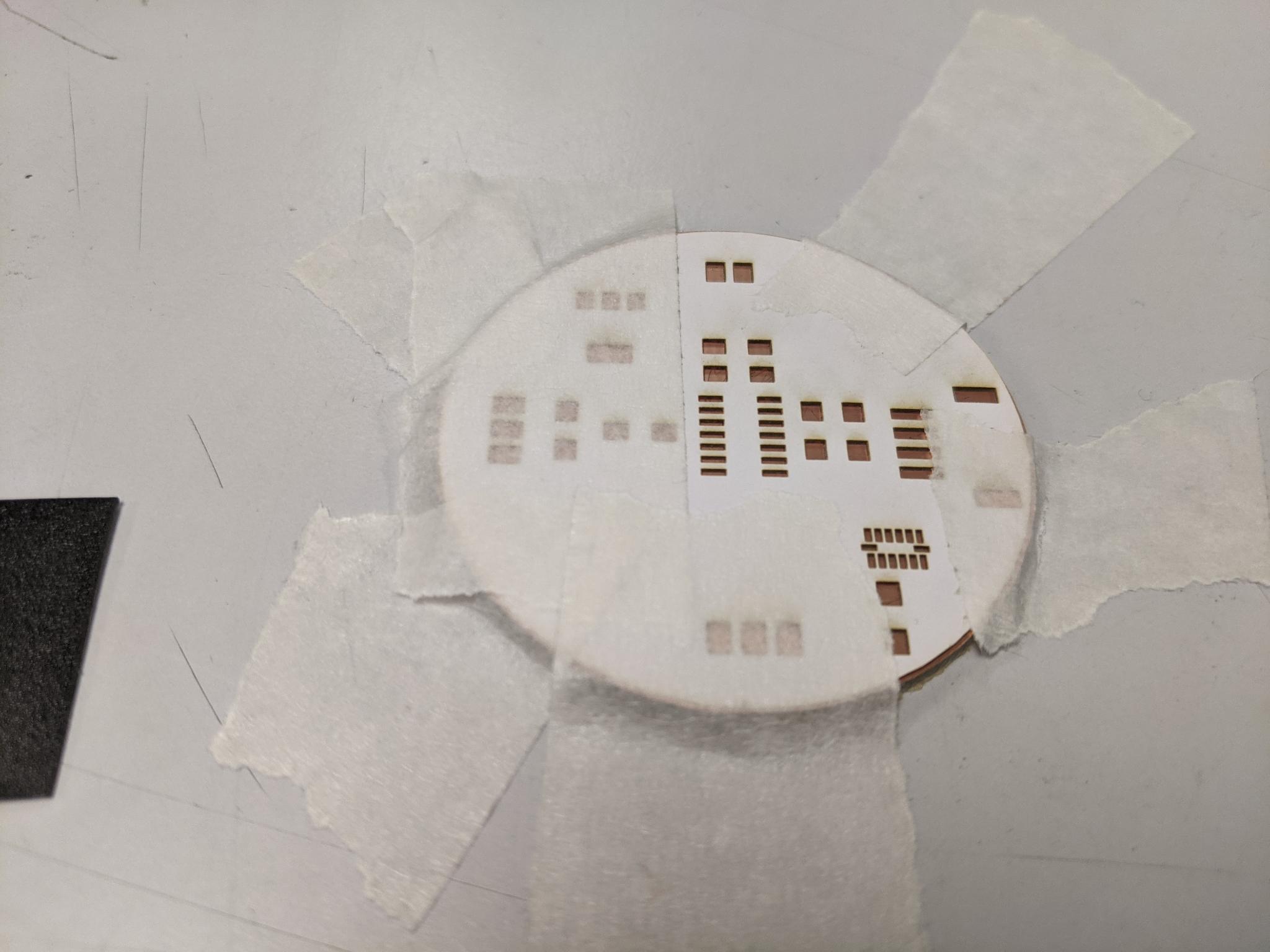
Well I didn't tape perfectly the board to the sacrificial board and some Z differences were too important for proper milling. I broke a 0.4mm mill but it can still do the NCC copper clearing. I chosed to copper clear only the boards with the contact pads. Also I had to recut some boards with a massicot.
Solder
led element contact pads
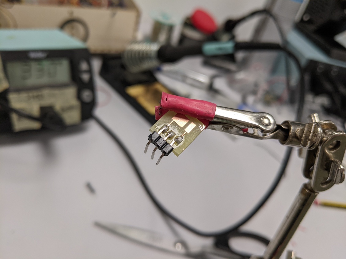
microcontroller contact pads
led element battery
Test
#include <tinyNeoPixel.h>

#define TRIG 3
#define STRIP_A 5

#define NUMPIXELS_A      16

tinyNeoPixel pixels_a = tinyNeoPixel(NUMPIXELS_A, STRIP_A, NEO_GRBW + NEO_KHZ800);

int delayval = 100;
int r= 200;
int g=20;
int b = 10;

int i=0;

void setup() {
  pinMode(TRIG, INPUT_PULLUP);
  pinMode(LED, OUTPUT);
  pixels_a.begin(); // This initializes the NeoPixel library.
  pixels_a.clear(); // This initializes the NeoPixel library.
}

void loop() {

  int trigState = digitalRead(TRIG);

  if (trigState==0){
    pixels_a.setPixelColor(i, pixels_a.Color(r, g, b)); // Moderately bright green color.
    pixels_a.show(); // This sends the updated pixel color to the hardware.
    delay(delayval); // Delay for a period of time (in milliseconds).
    i=i+1;
  }

  else {
  digitalWrite(LED, LOW);
  }

  delay(1);

}
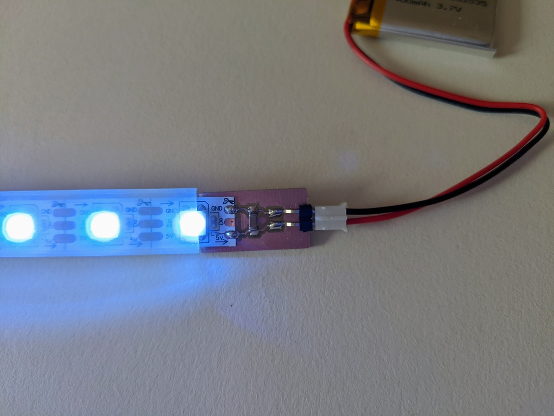
Final overview
Once I was done testing and uploading sketches to the microcontroller I powered the circuit with a USB sector power supply, 5V. I used the USB power port designed on my board and an USB extension cable.
The led element is powered with a 3.7V LiPo Cell battery.
Here are pictures of the global setup and more detailed pictures of the little PCBs made this week.
Files
All the following folders contains the KiCad file with the electric schematic and the PCB design, as well as the plotted gerber files for F.Cu and the Edge Cuts. Note that the Edge Cuts should be redesigned in any case, according to the structure design evolution.
Week 11 - Input devices
Week's explorations and achievments
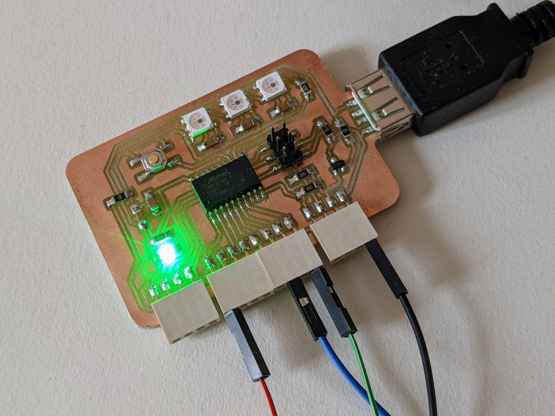
I oriented this week's work towards accelerometers.
- I first picked the SMD tiny component ADXL 343 that we had in the lab.
- I draw the general design of a new board with an ATtiny1614 and chose the components and features: the ADXL 343 working with I2C, an I2C grove connector and headers for a led strip
- I designed it in KiCad
- I milled it
- I soldered the components, and discovered how to use solder paste with a paper mask
- I programmed it via UPDI
- I could achieve serial communication
- I downloaded the Adafruit libraries
- I couldn't make the ADXL 343 to work
- Browsing through some other students documentation I realised I missed something in the datasheet
- I went back to the datasheet to use ADXL 343 with I2C
- I made a small adjustment on my board (connect the ADXL 343 pins CS and VDD and elongate its pads)
- I milled it, soldered it, programmed it
- The ADXL 343 wasn't recognised by the programm
I2C-scanner:,(
- I moved forward with a simpler component to use, the Adafruit breakout board with a MMA8458.
- I connected it to my I2C grove on my second board
- I downloaded the Adafruit library
- I uploaded the demo example which worked
- I observed in the serial port the evolution of the x, y and z informations while moving the accelerometer
- I adapted the example code to better understand how to manipulate the library's parameters
- I first use the orientation predefined cases to light up the led strip with different colors
- I then tried to detect variations illustrating a shaking movement. I started with w and introduced two measures of x delayed by a few milliseconds, in order to trigger specific actions if this difference is above a certain level
- I detected the important variations on x, y and z axis which triggered the strip lighting in various colors (red for x, green for y, blue for z)
- I modified the code to control the led colors as I intend to do in my final project
- I played around with the formulas to obtain a color gradient between the two colors at each tip of the strip
- It worked 8-)
- I ultimately modified my design and produced a third board without an ADXL343
We unfortunately didn't have the time for the group assignment :(
An idea using an accelerometer for my palette palet:
The idea I've partly demonstrated this week with an accelerometer:
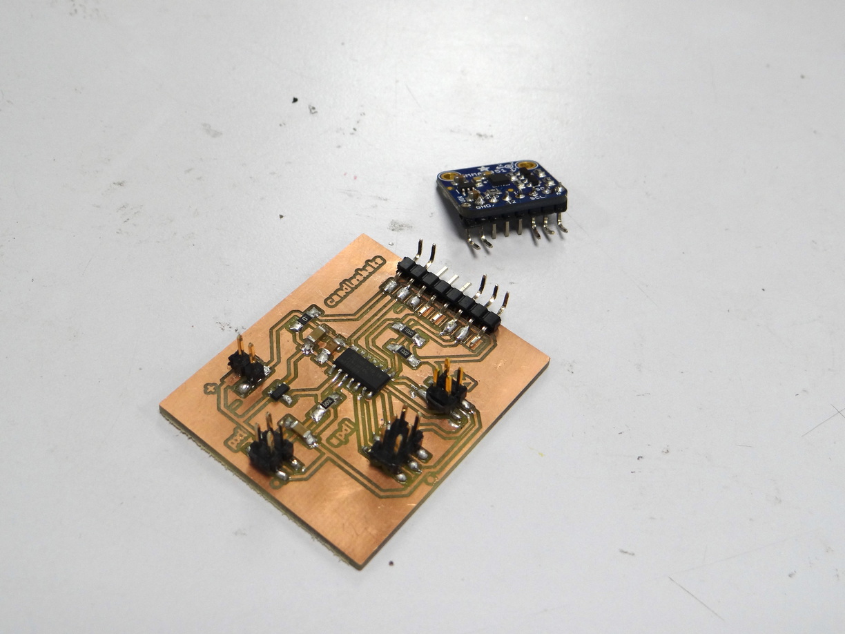
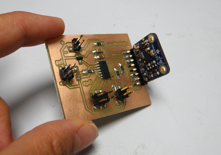
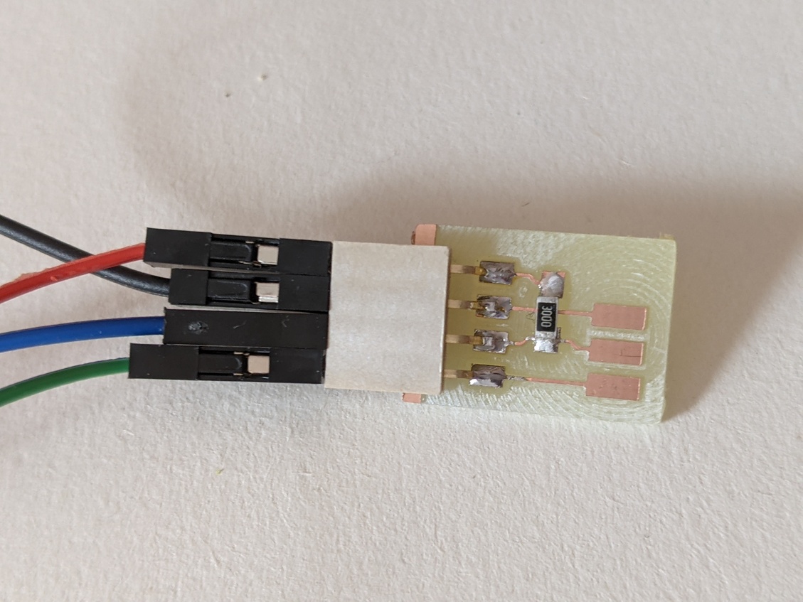
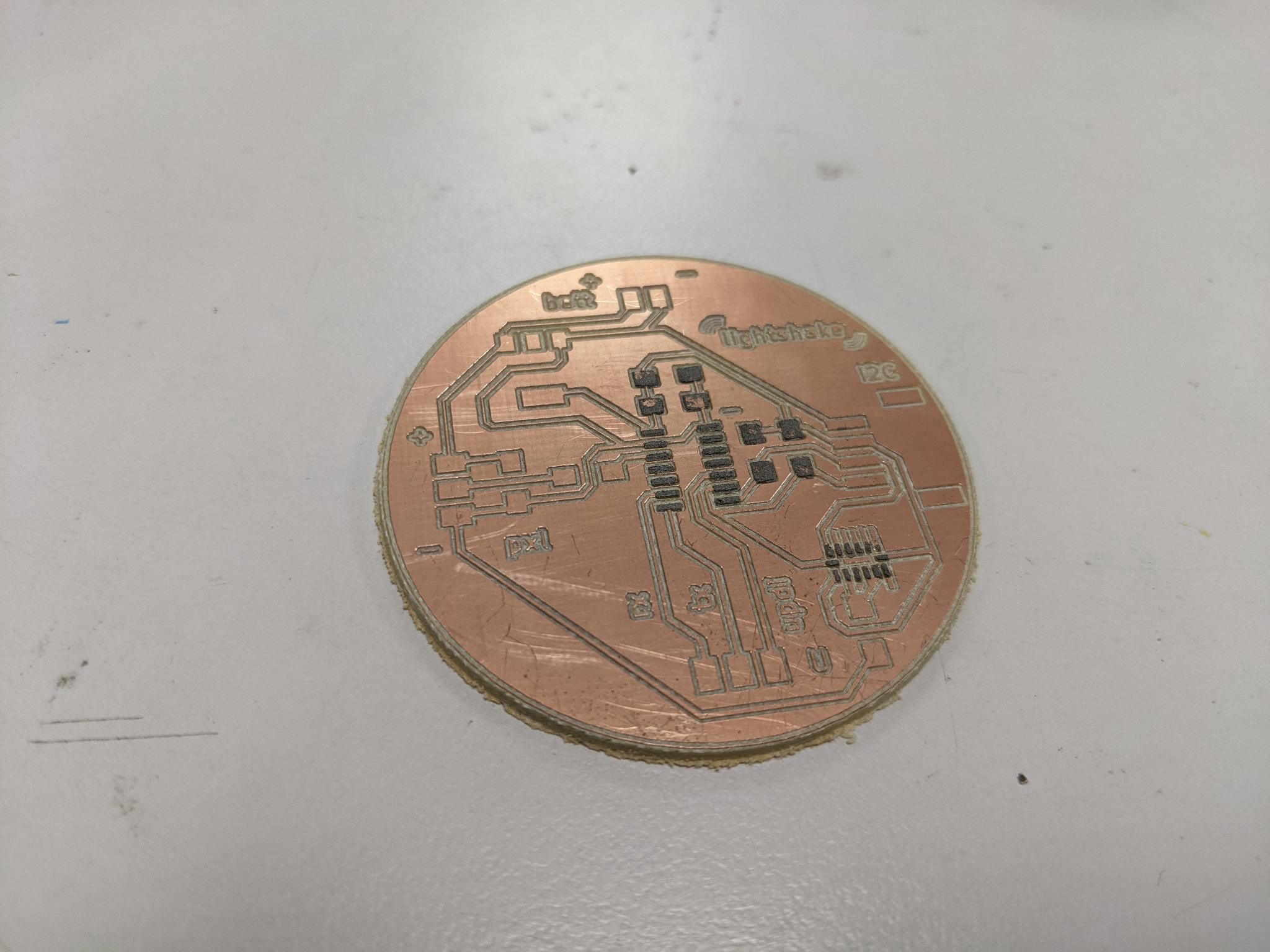
Three boards made this week:
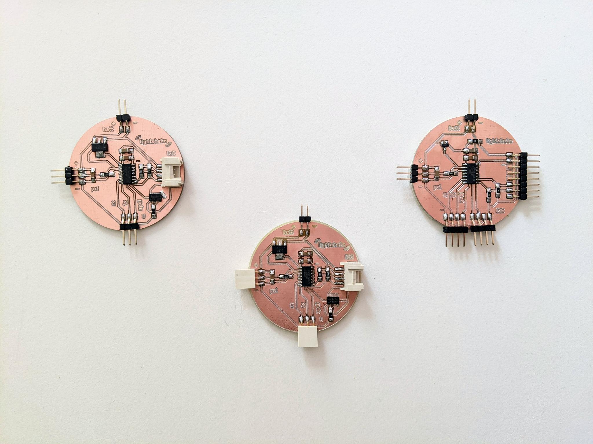
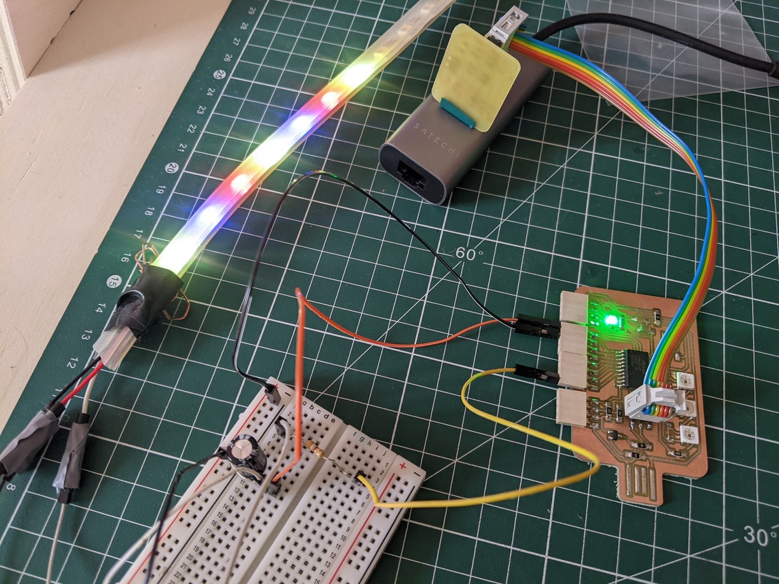
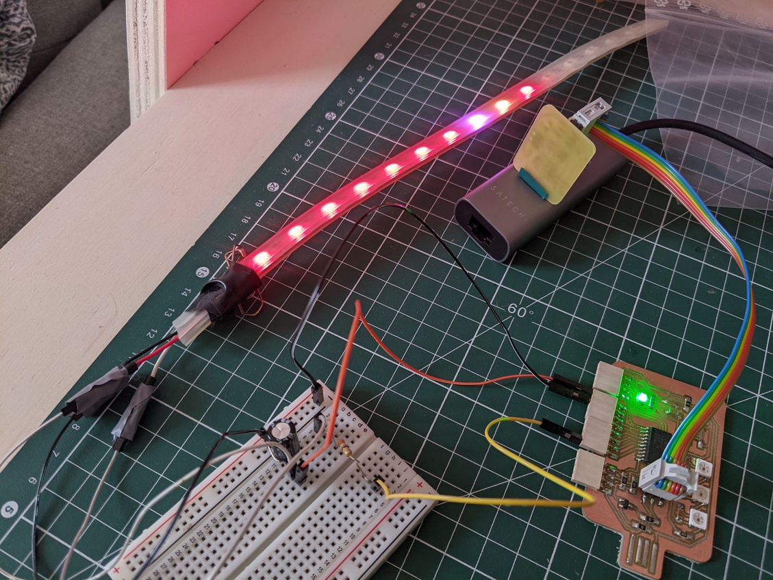
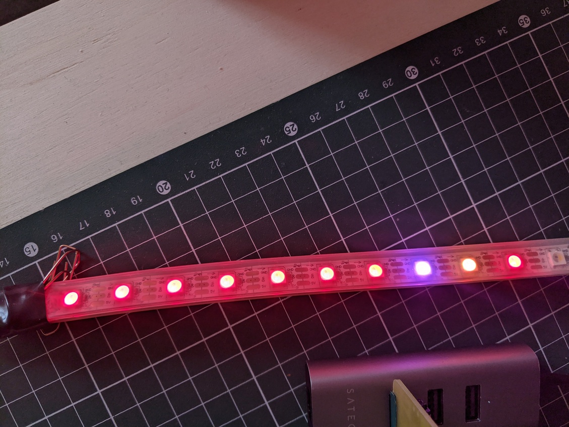
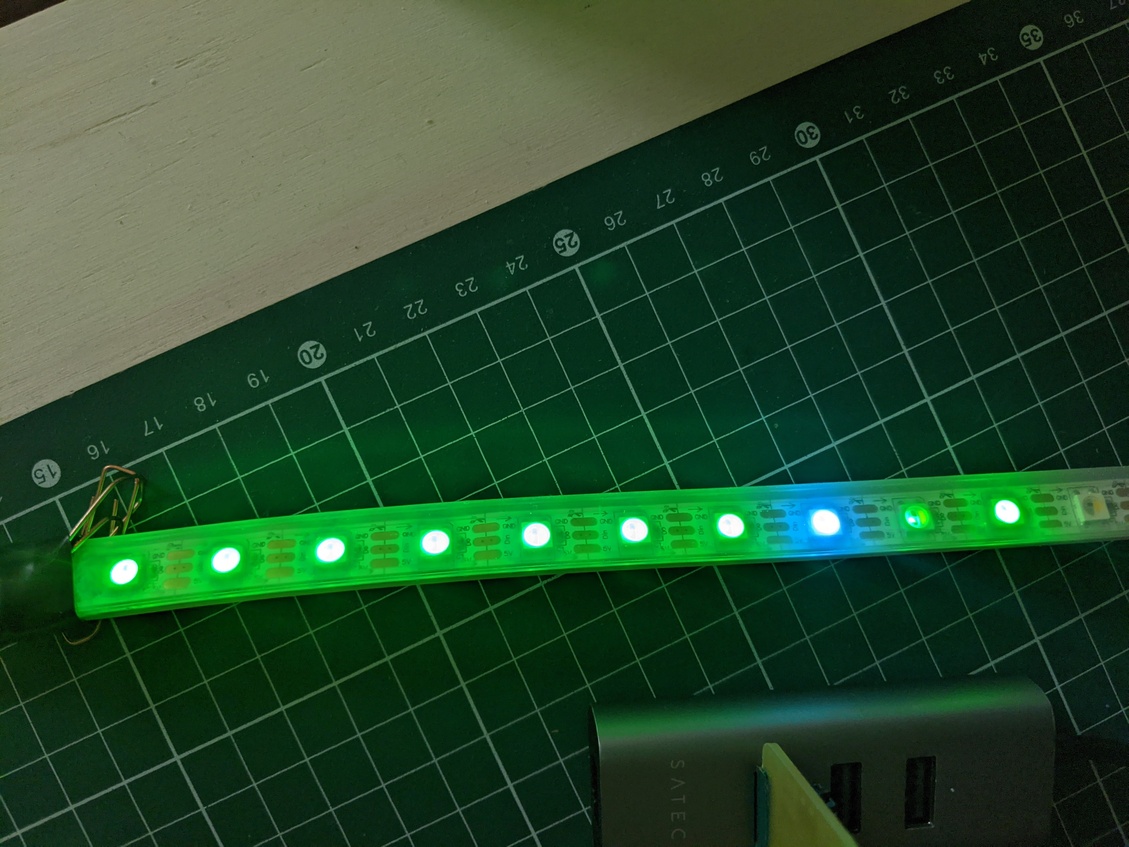
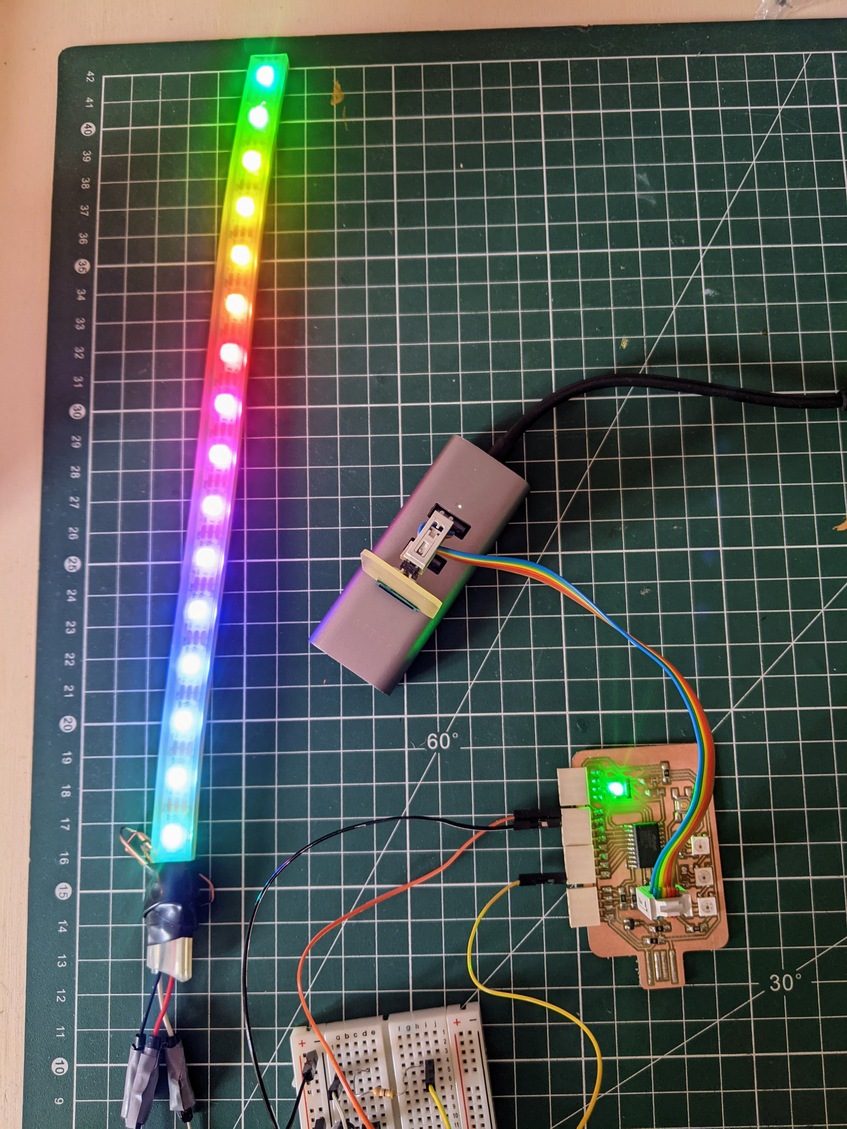
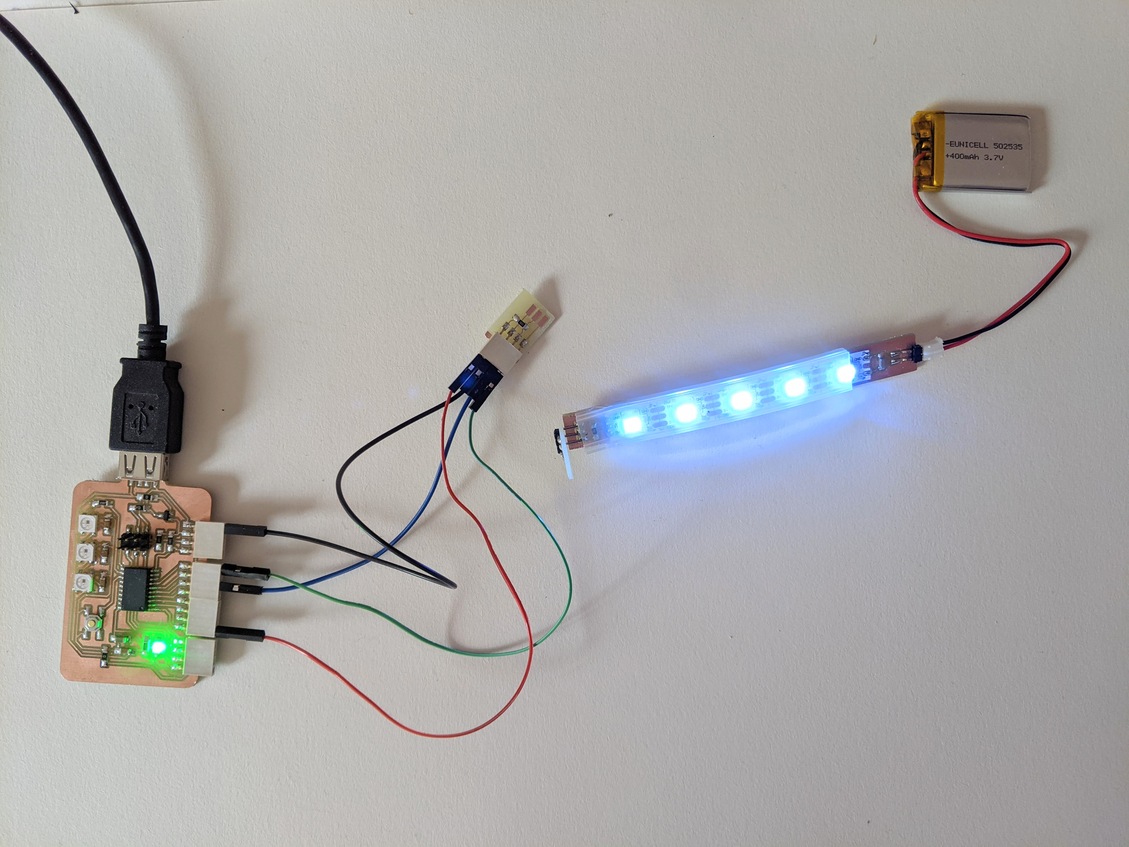
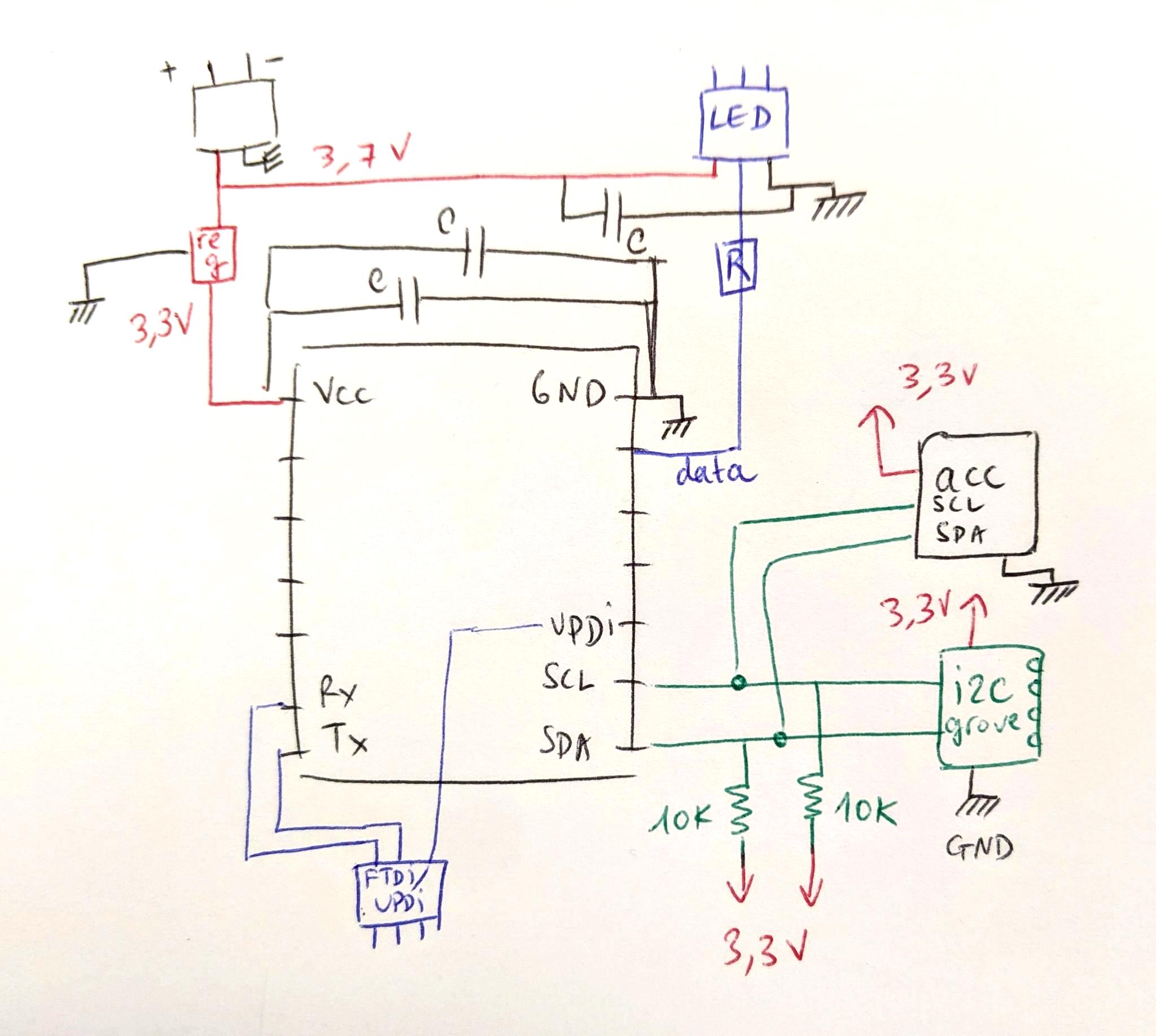
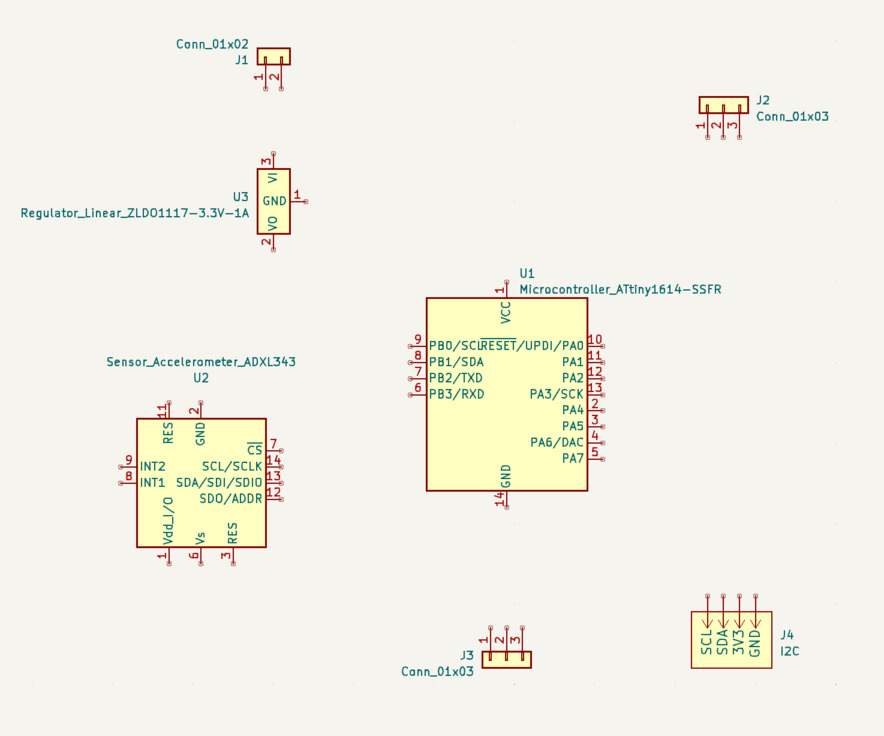
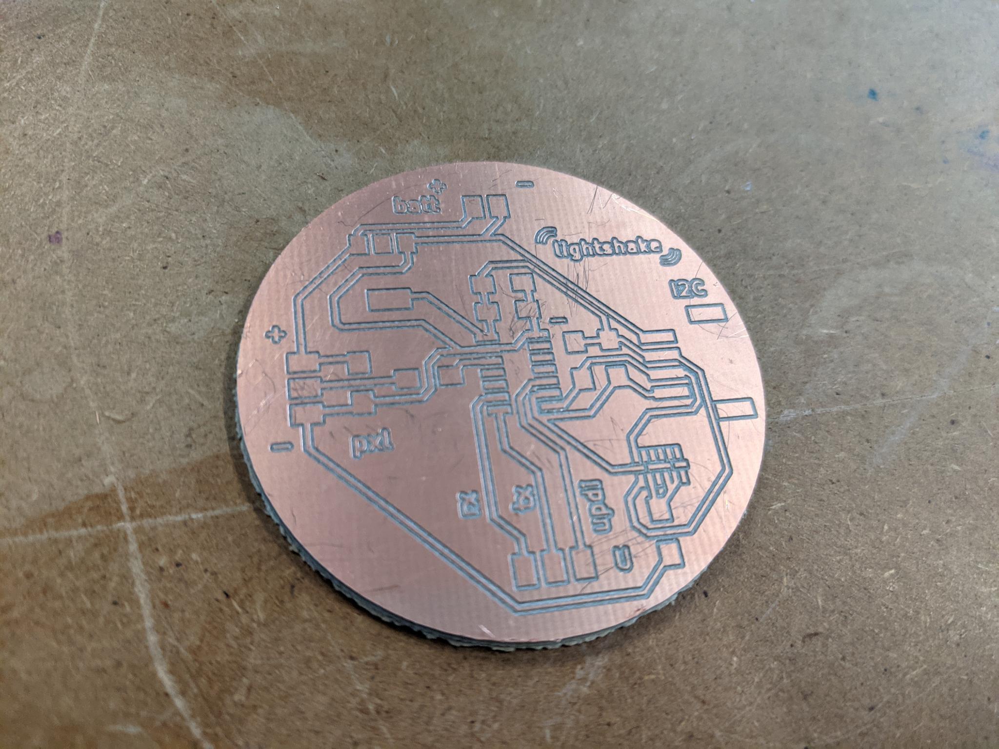
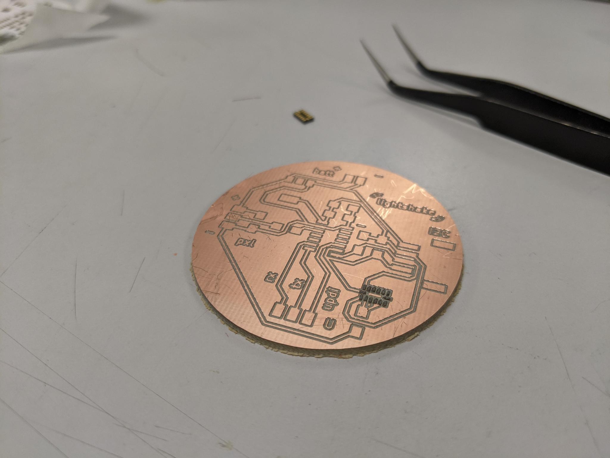
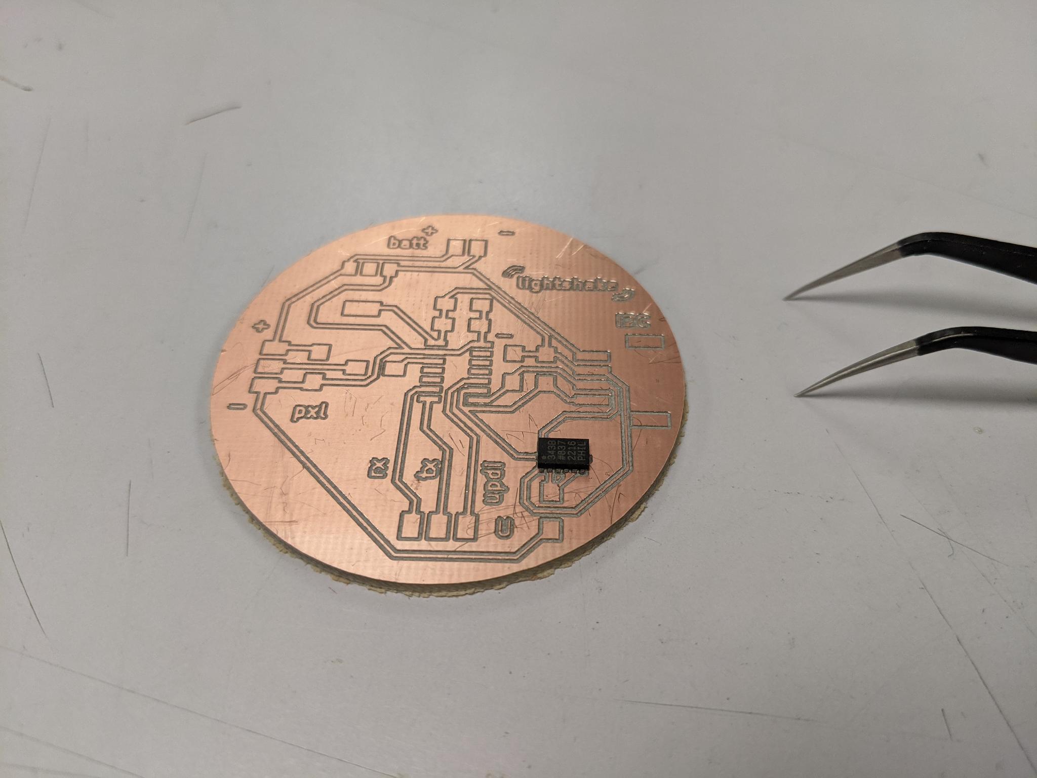
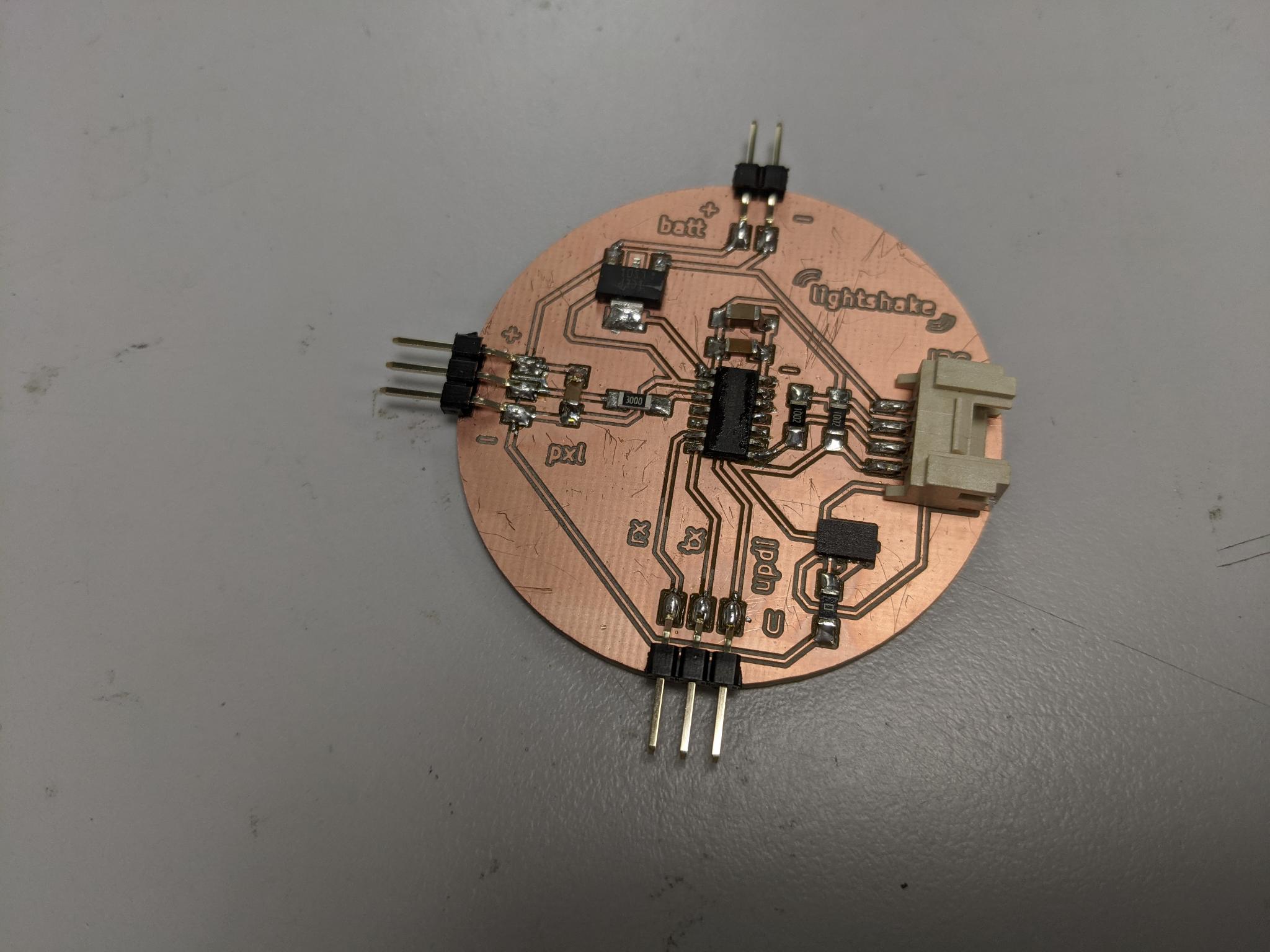
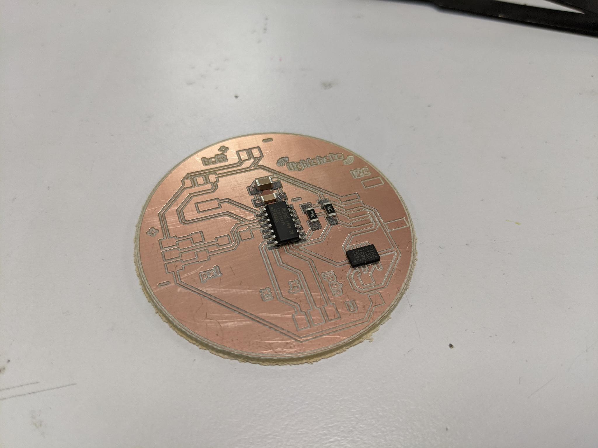
New lightshake I2C board
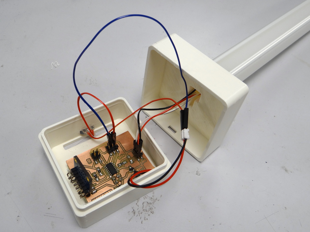
The final goal for this board is to be integrated into a light tube. The tube can be 'filled' with different colors at each tip of the led strip. When shaken, the colors must blend.
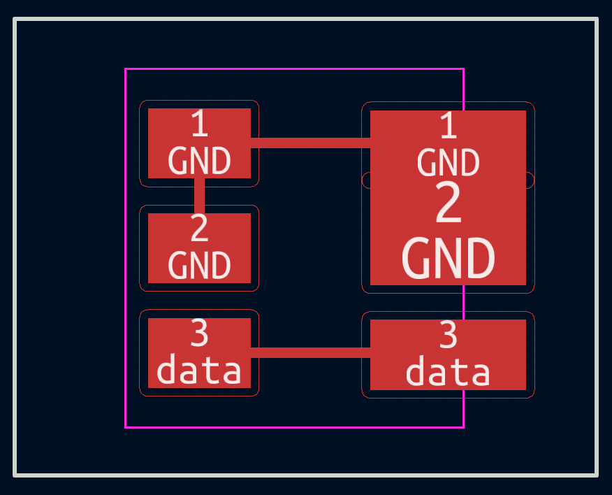
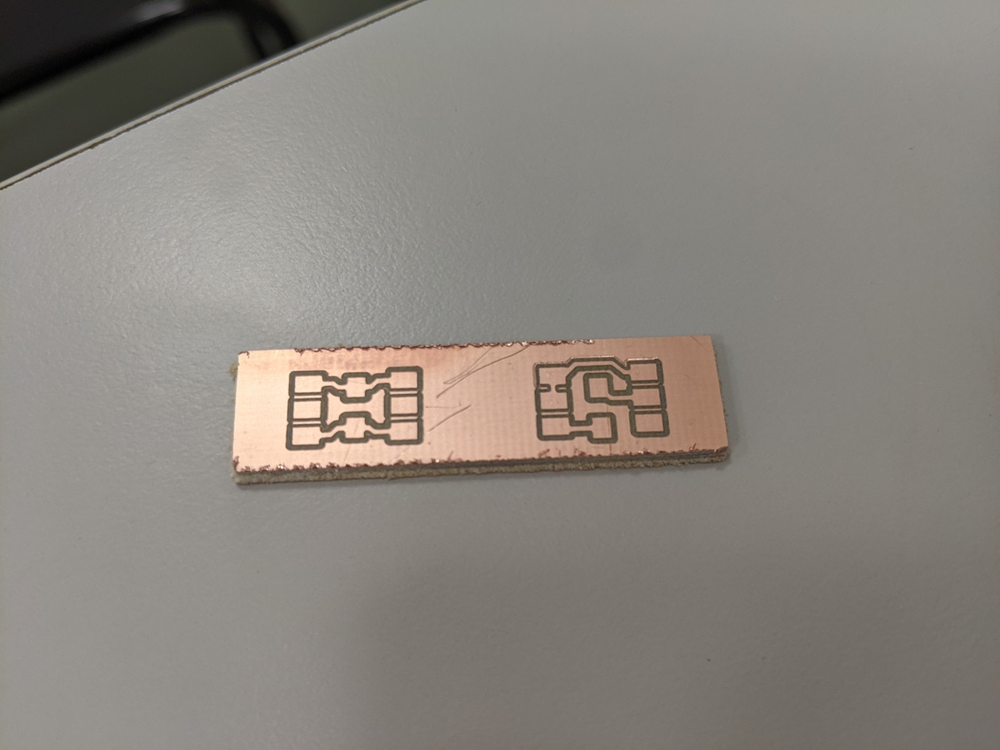
The board works thanks to an ATtiny1614. It can thus be programmed through UPDI with the help of an external UPDI board programmer. It can communicate with the serial monitor thanks to the FTDI provided by the same external programmer. It is powered either by USB if connected to the programmer, or with a 3.7V Lipo battery. It provides header pins to connect a LED strip It provides an I2C grove connector for further communication with another circuit.
Components
| Components name | Description, use | Value / Specs | Package informations | Datasheet or vendor link |
|---|---|---|---|---|
| ATtiny1614 | Microcontroller | SOIC14 | datasheet | |
| 2 capacitors | Filter the signal for the microcontroller | 1uF and 100nF | 1206 | |
| ADXL343 | 3 axis accelerometer | SOIC14 | datasheet | |
| ZLDO1117 1A 3.3V | Voltage regulator | SOT 223 3 | ||
| 2 pullup resistors | On SCL and SCL lines | 10kOhm | 1206 | |
| 1 capacitor | Filters the signal for the led strip | 470nF | 1206 | |
| 1 resistor | to protect the led strip | 300 Ohms | 1206 | |
| BH2103220019- 90 D grove | grove connector for I2C communication | 300 Ohms | 1206 | |
| 3 pins header horizontal | for the UPDI / FTDI communication | 1x03 | 2.54mm | |
| 3 pins header horizontal | fto connect the led strip | 1x03 | 2.54mm | |
| 2 pins header horizontal | to plug the LiPo battery | 1x02 | 2.54mm |
External components :
- RGB WS2812B leds strip
- 3.7V LiPo Battery
- UPDI / FTDI porogrammer board (only to programm and test)
- USB male-female cable (only to programm and test)
Design
I started with a paper sketch.
I thus transposed it in KiCad. I already had all the symbol (the ADXL343 is in the fab library) except the grove connector that my instructor send me. I put it in my repository alobng with the kicad files.
I ran the electricam rules checker which gave me two pieces of information:
- Missing connections. I thus indicated which line shouldn't be connected (see next screenshot)
- Missing power input. This is normal because my battery is external and not indicated on the schematic. But maybe there's a cleaner way to indicate it.
Routing
Routing was okay but a bit long as usual, and I had to use a zero ohm resistor.
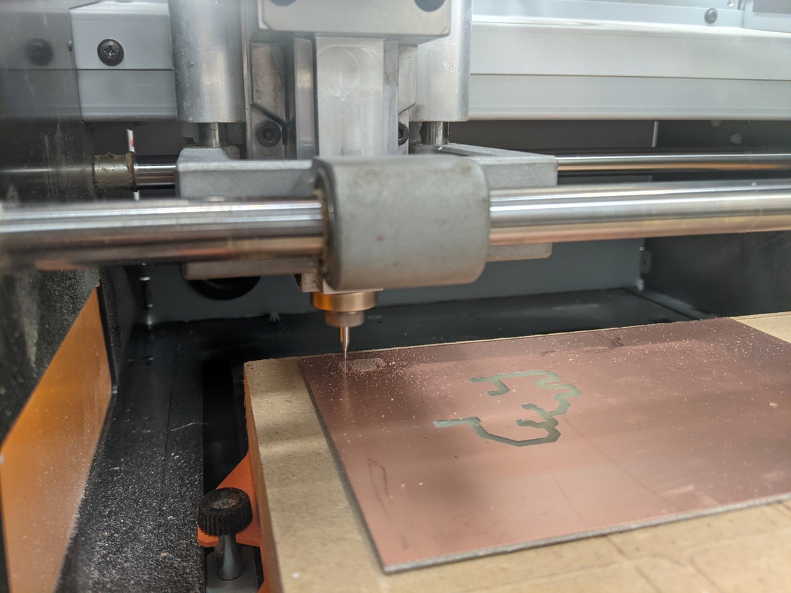
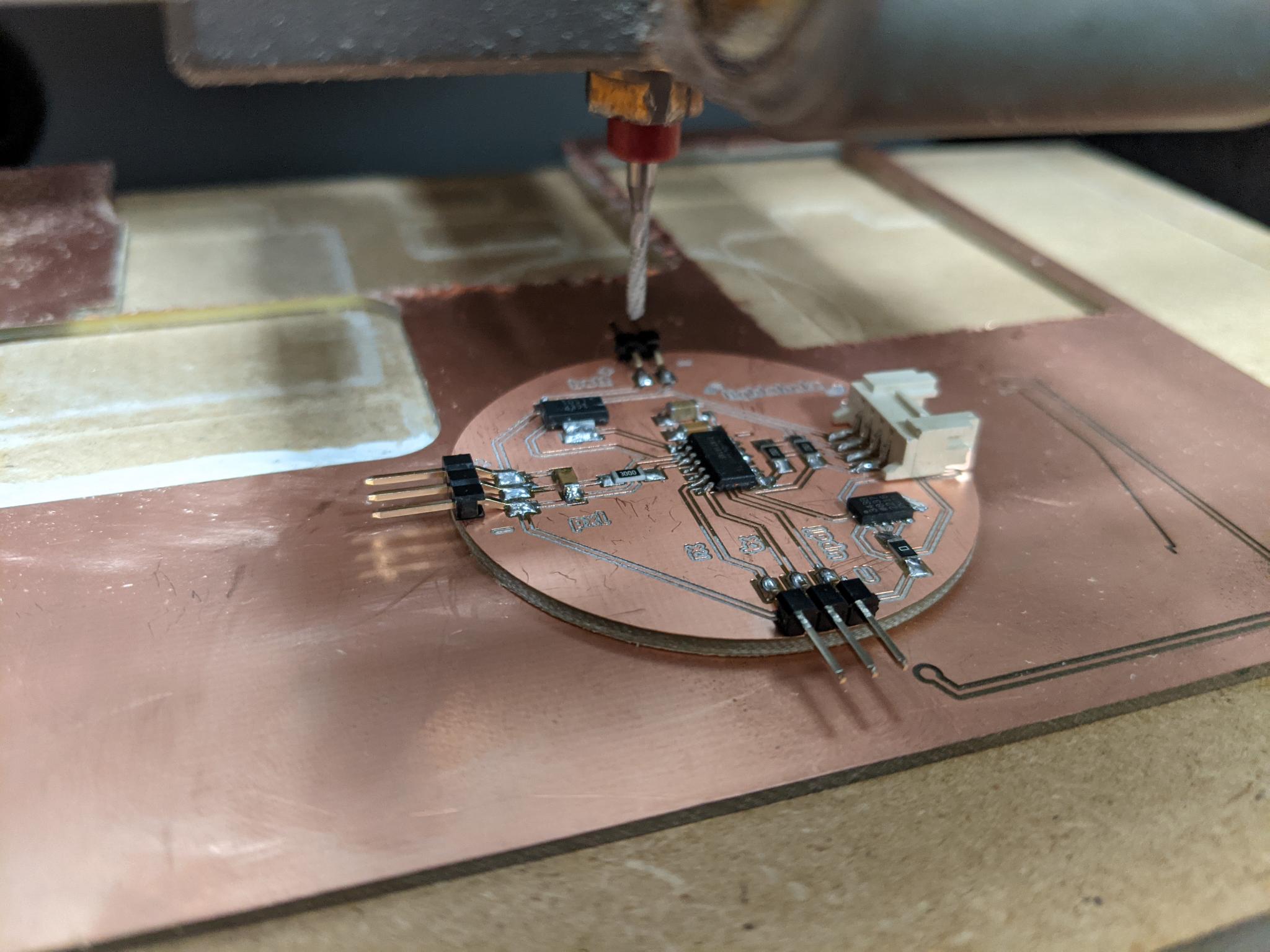
Mill
At first I tought of using a 0.4 mm mill to trace the tracks, but the pads of the AXL343 are too close for that. So I used a V-shape mill (for the first time !).
- I carefully zeroed the mill on the top copper surface, almost ten times, to really be sure to set zero on the lowest point.
- I entered 0.2 diameter mill in FlatCam with the following parameters:
- Cut Z : -0.06 mm
- Travel Z : 2
- End move Z : 15
- Feedrate X-Y : 180 mm/min
- Feedrate Z : 100 mm/min
- Spindle speed : 8000 tours/min
I was impressed by the speed of it, compared to the cylindric ones!
Everything went fine. When I had to mill a second board I was less lucky with the z-level of the copper plate and the traces were more irregular but they still worked though.
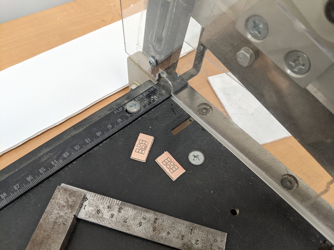
- I did the edge cutting with a 2mm cylindric mill, same parameter as in Electronics production.
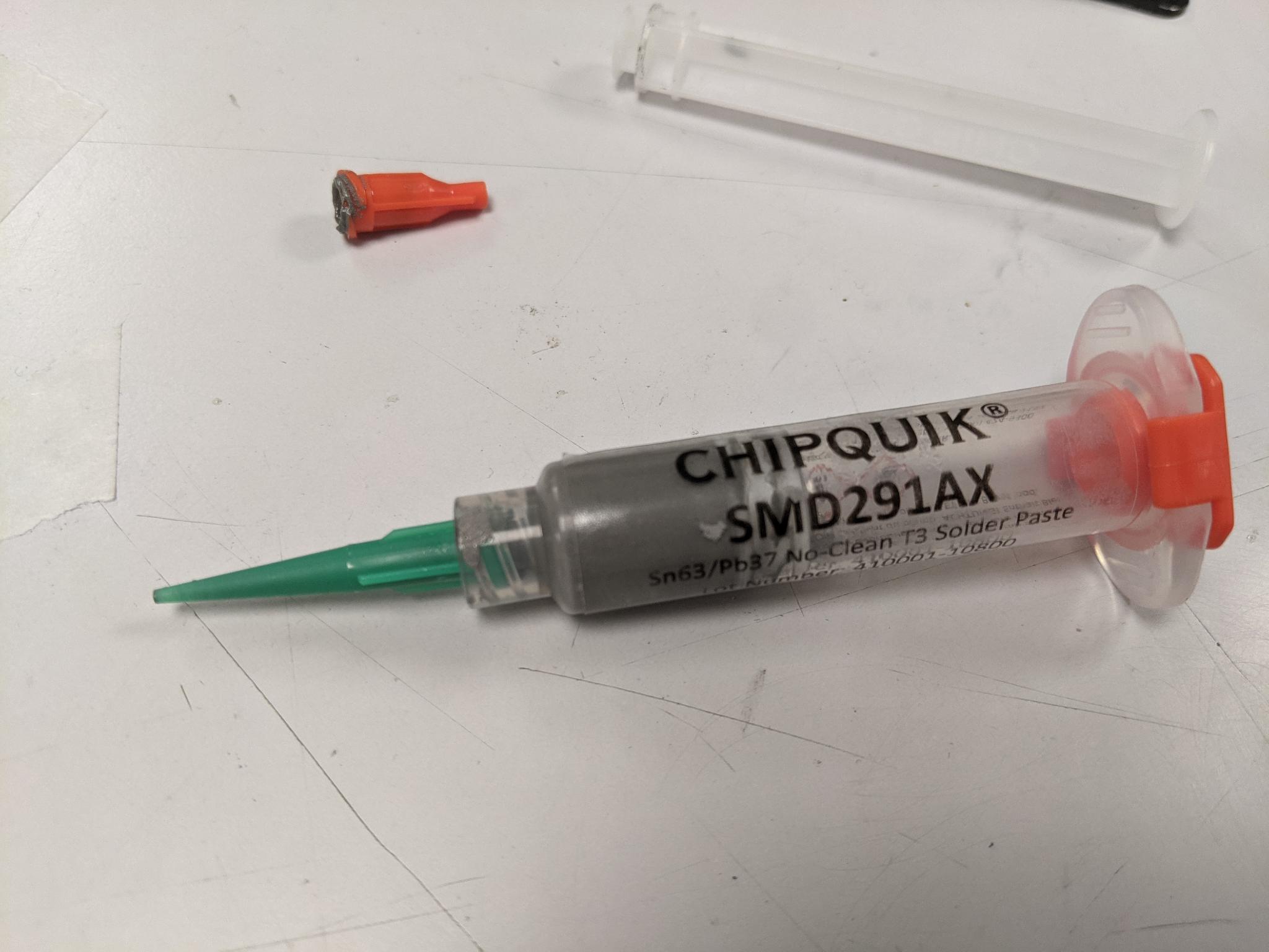
Solder paste and paper mask
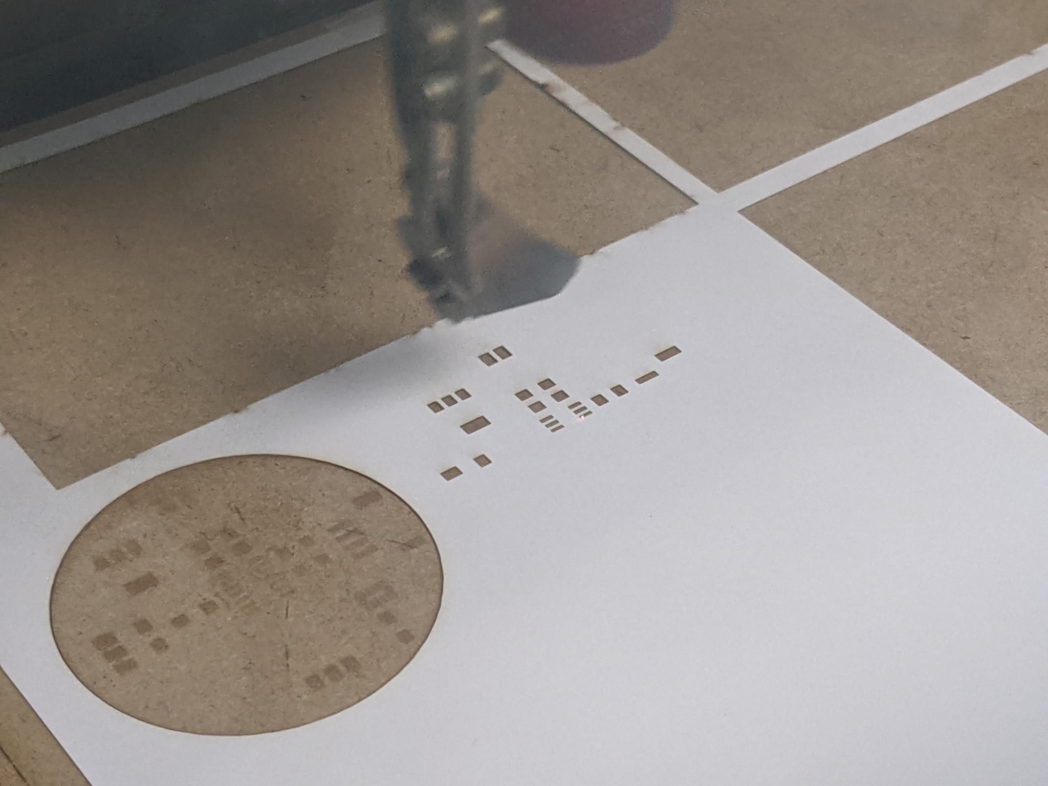
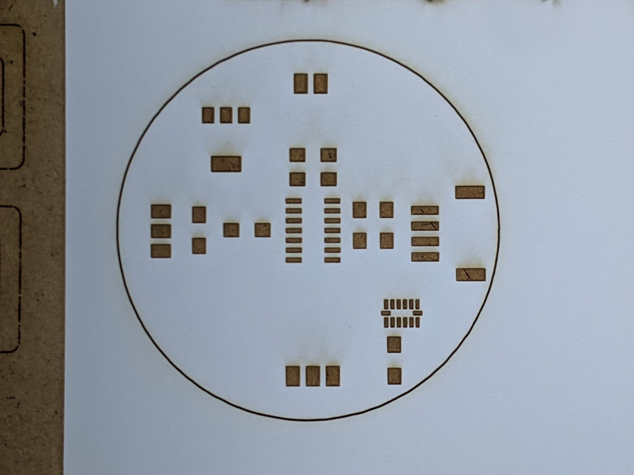
As the ADXL343 package is really small AND has its pads underneath the component, I had to use solder paste. To be sure to put solder paste only on the pads, I used a paper mask etched with the laser cutting machine
To create the paper mask:
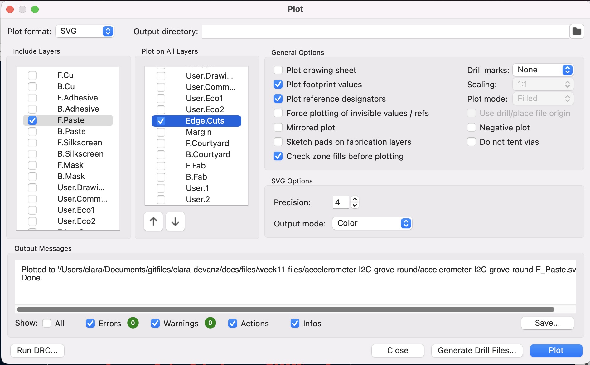
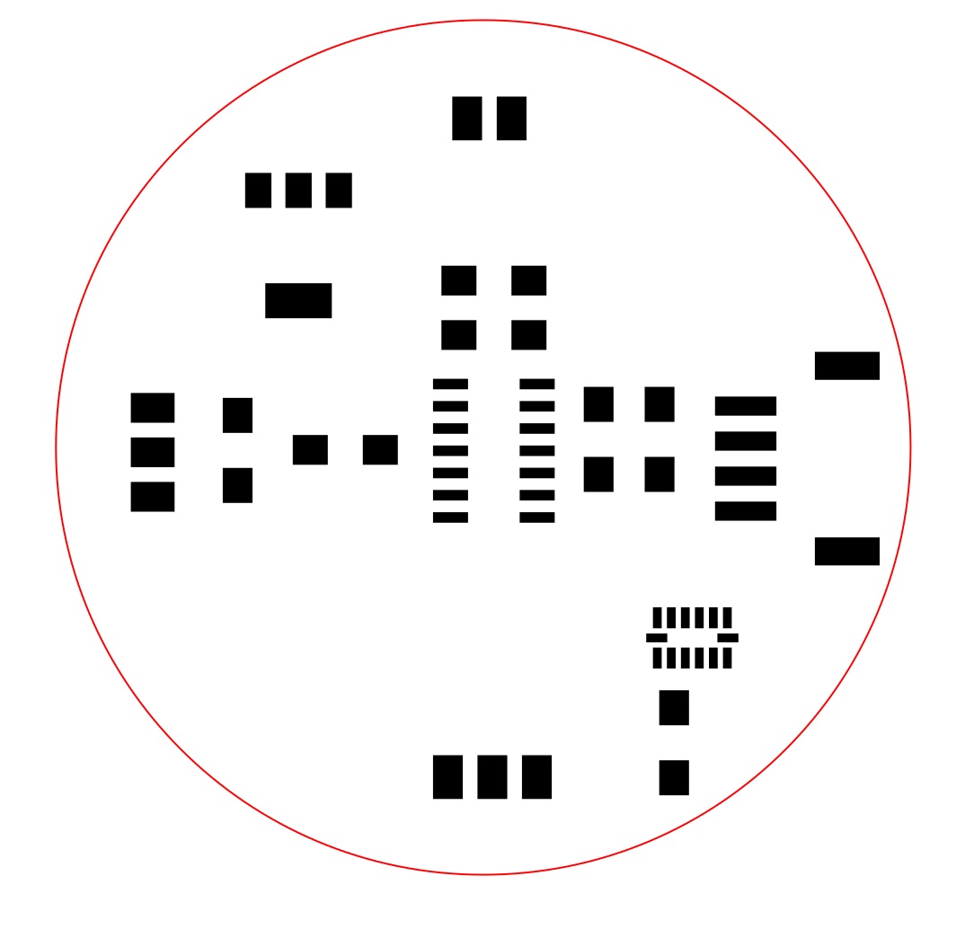
- In Kicad, plot the layer F.Paste in
.svg. Be sure to also tick to add Edge cuts on the file.
- In Inkscape, change the fill and outline properties for laser cutting process: engrave the pads and cut the edges. In our case engraving is black filling and cutting red outline. We engrave the pads and not cut their outlines because it allows us to have a better fidelity to the pads dimensions.
- Tape the paper to a mdf sacrificial board. I used a white paper with a thickness of 120g/m2.
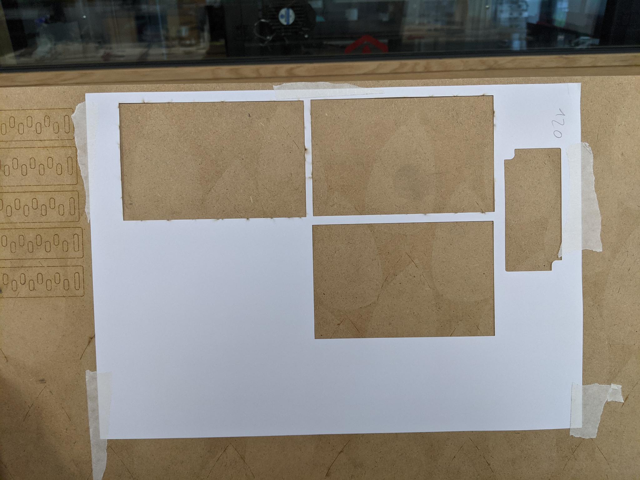
-
Launche the job on the laser cutting machine. I used the trotec Speedy 100 because it's the machine my colleague had done its settings for. The parameters are the following:
- Cutting: 32% Power, 5% Speed, 2 passes
- Engraving: 20% Power, 10% Speed, 1 pass
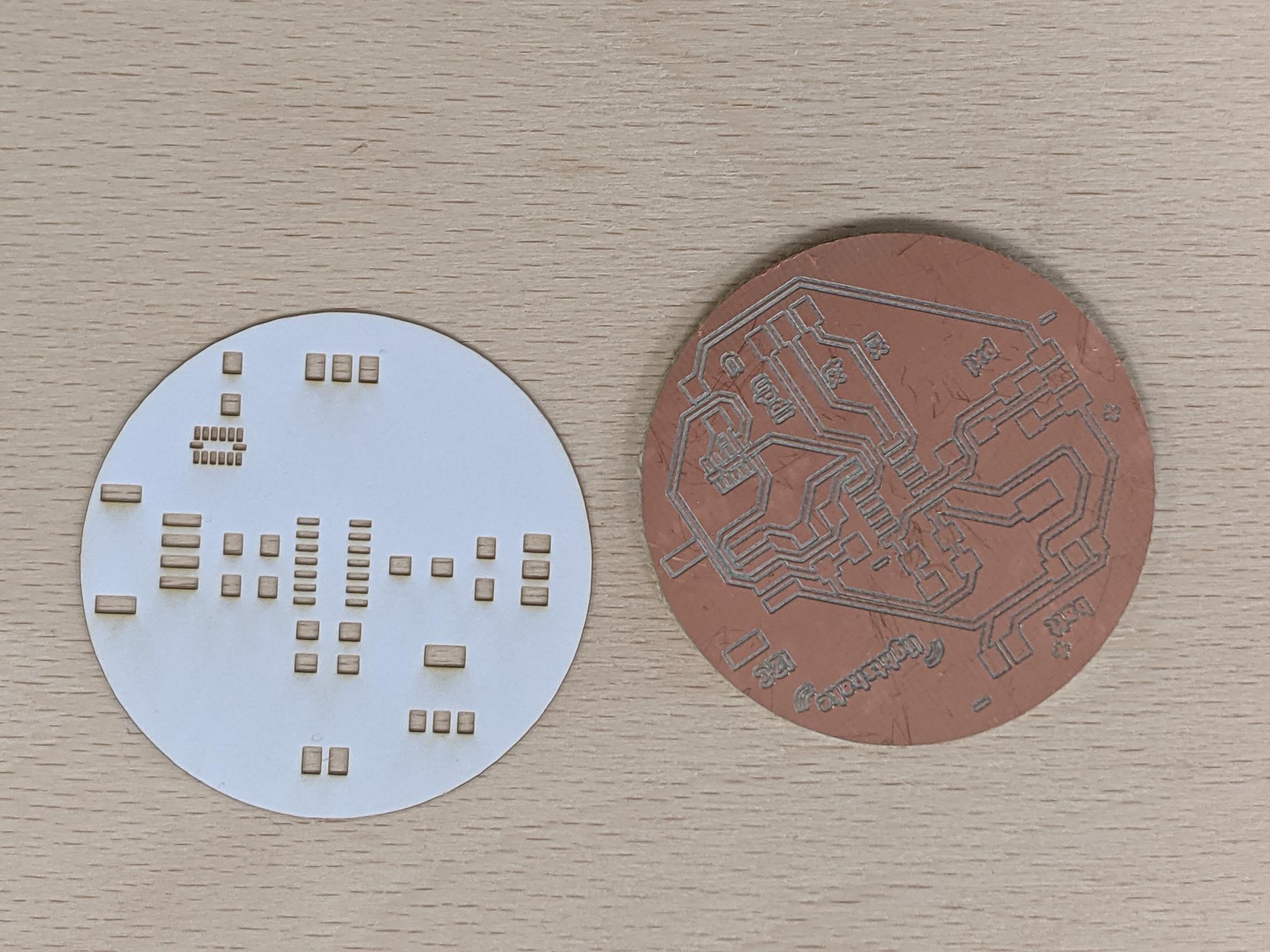
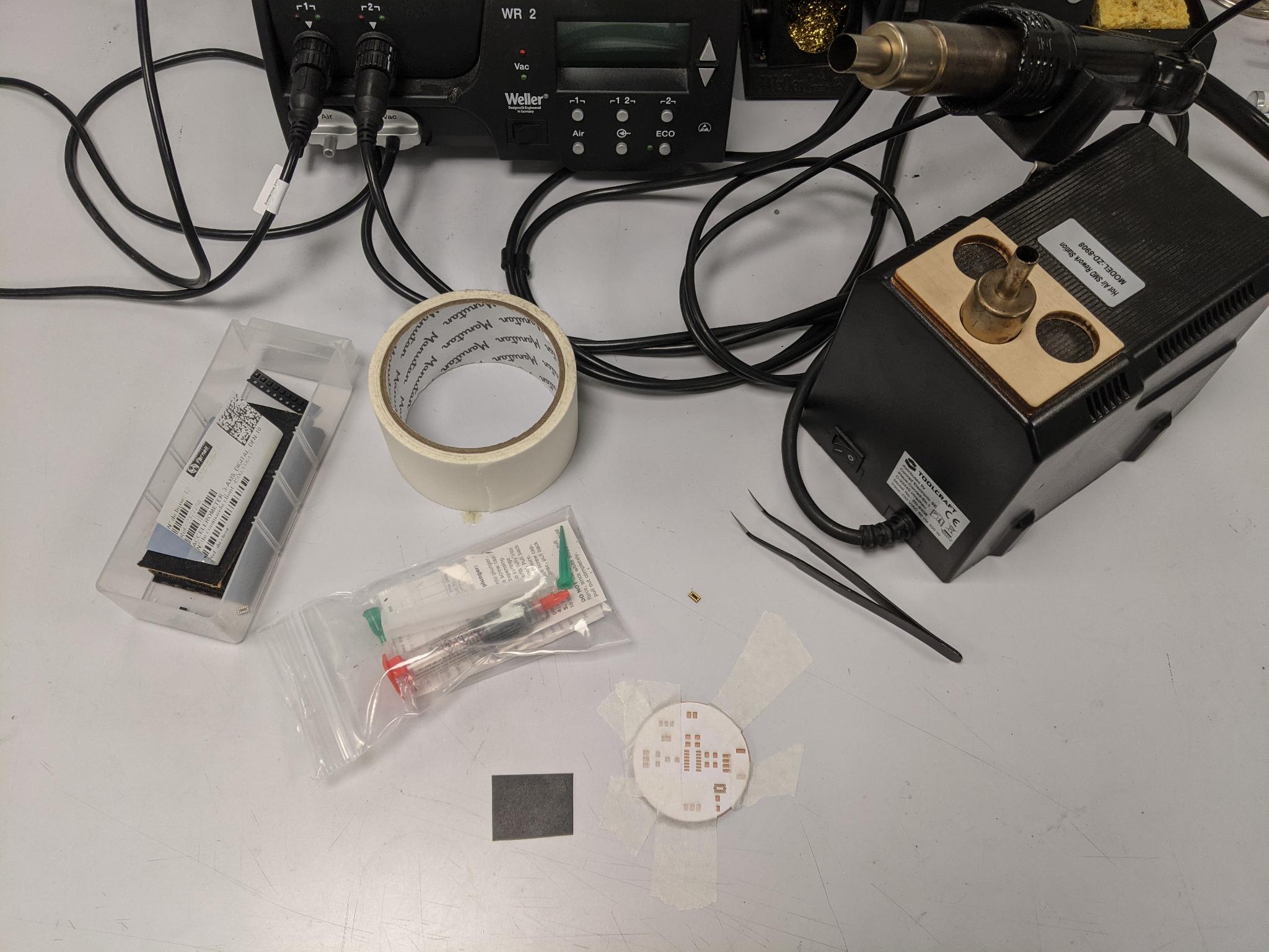
Once you have your paper mask, gather all the material:
- Solder paste (you have to store it in the fridge) with all its accessories: plastic push syringe, fine tips...
- A piece of flexible plastic (such as thin PP) to spread the paste
- Tape to attach the mask and PCB to the table
- A heat gun
- The component(s) you'll solder (in my case the ADXL343)
- Small pliers
Place the mask precisely on top the PCB and tape it to the table (my PCB stuck to the table because there was still double-sided tape from the milling process). Open the solder paste tube and screw the tip.
Spread the solder paste through the mask with the flexible piece of plastic. Take off the mask carefully.
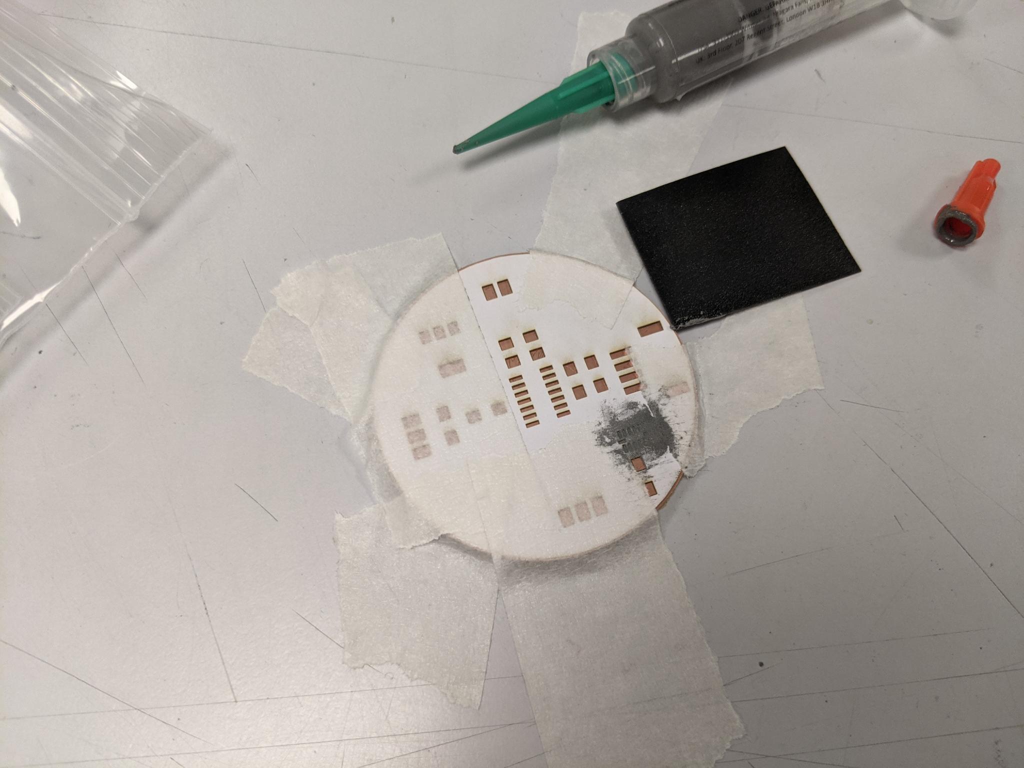
Place delicately the component on the solder paste.
Change the heat gun tip for a large one, then heat the heat gun to a high temperature near 270°C. Approch it slowly from above to your component. Keep the heat gun above the component until you see the paste starting to melt and shine.
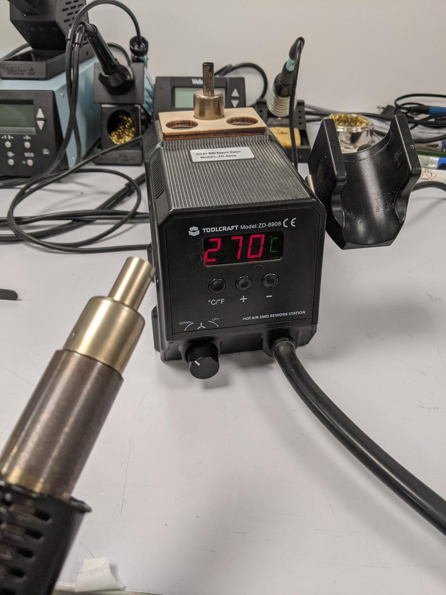
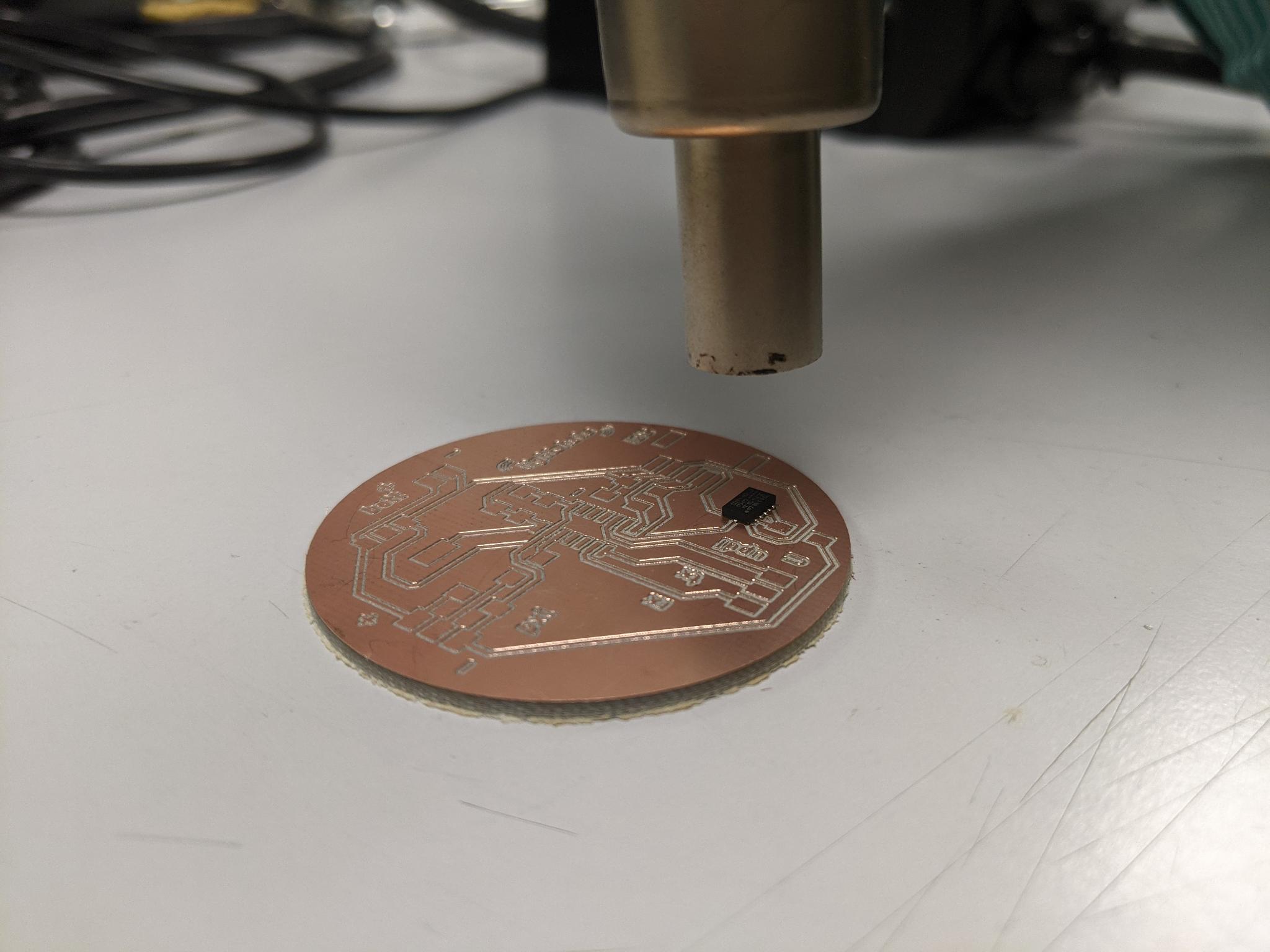
Done ! Check for short circuits. I soldered the other (way bigger) components by hand.
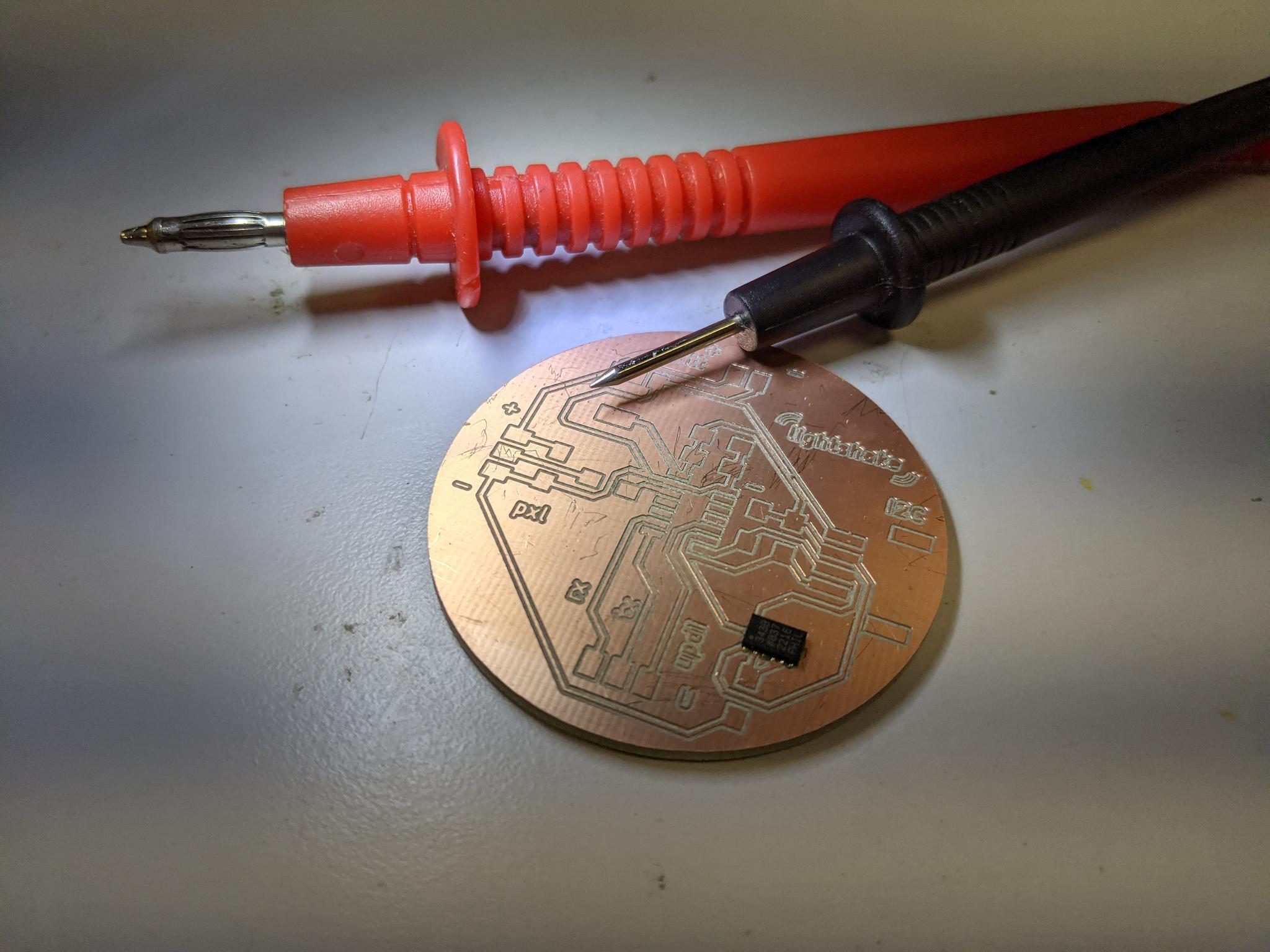
Software side
I first checked that I could program my board with UPDI. Don't forget to also connect the ground reference!! And the Vcc if you want anything to happen.
I could light up a led strip, so success for that step!
I also tested the serial communication by connecting Rx and Tx. I had some challenges here, inverted Rx and Tx and eventually managed to have some information in the serial monitor.
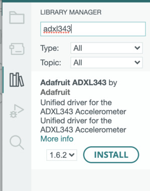
Then in order to use the ADXL I downloaded the Adafruit_ADXL343.h library, along with the depedencies Adafruit Unified Sensor and Adafruit BusIO. I already had installed Wire.h that you need for I2C communication.
But then I was really lost.
ADXL issues
Confident that the hardware was working fine, I tried programming the accelerator ADXL343 but was quite lost in the examples. I tried reading the code provided by Neil but it was way too low level from what I was used to code (also he used another ATtiny than me). I got quite upset about the lack of guidance about that component even if it was on the fabacademy list of material.
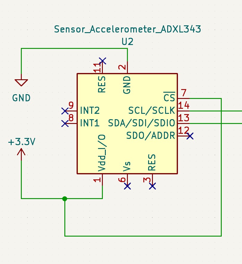
I browsed the documentation of other students to realise I had missed an important point of the documentation, that is that the ADXL pin CS must be connected to VDD in order to use it with I2C. My bad, I was too quick on my wiring!
Instructor's advice: When you have such a component with the pads hidden underneath, trace some tracks going a bit further out for each pin, if you have to hand wire anything afterwards.
I2C pinout
As mentionned in the datasheet, in order to allow the I2C protocol on the ADXL343, CS needs to be connected to VDD. I thus modified my design.
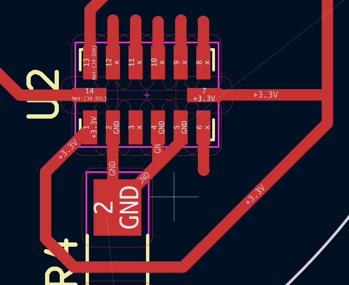
I then milled it. The horizontality was worse than for the first board but I somehow managed to mill the tracks correctly. Let's go back to paper mask, solder paste, hand soldering...
Short circuits?
Unfortunately I couldn't obtain any result with this new board. As suggested my instructor I ran an I2C-scanner script to check if anything is plugged in I2C. My AXL343 is supposed to be on the I2C bus so it should appear. But obviously it's not the case, so there's probably an hardware issue such as a short circuit.

Well I'll move on for this week to an easier component (hardware and software speaking).
MMA8458 breakout board
Getting started
I then decided to use the MMA8458 Adafruit's breakout board, which also features a 3-axis accelerometer and I2C communication. For the hardware it was pretty straight forward as I had provided an I2C grove connector on my board. I just had to solder the pins to the breakout board. To do this you use a breadboard to hold the pins vertically, then classic hand soldering.
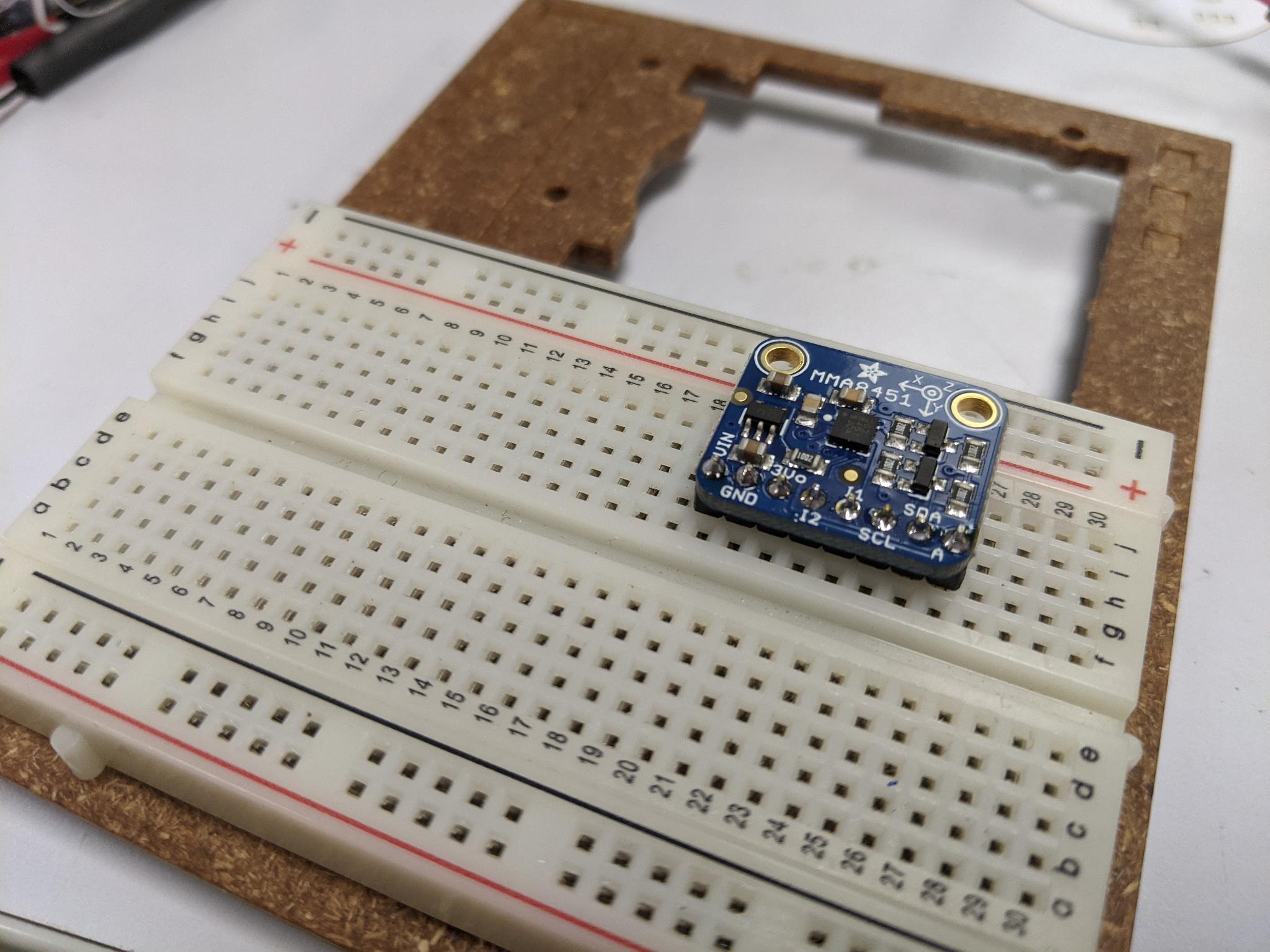
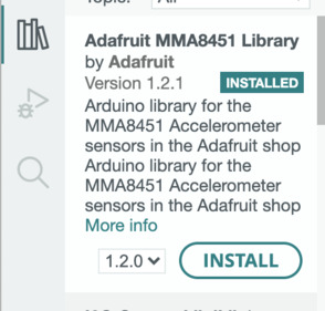
I started by downloading the Adafruit_MMA8451.h library.
If you haven't done it before you should check that you also have Wire.h library installed for I2C communication and Adafruit_Sensor.h for unified sensor functions and tinyNeoPixel.h library if you plan to use neopixel strips like me.
I uploaded successefully the MMA8451demo example provided with the library. It sends information about the axis orientation in the serial monitor, according to the orientation of the breakout board.
Serial communication remarks: Don't forget to switch port from UPDI to FTDI to read the information in the serial port. Also you might need to invert Rx and Tx wire if it doesn't work the first time
Here's an example of what's printed in the serial monitor:
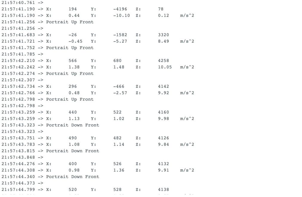
You can read more about the parameters retrieved and how they're processed in the library file Adafruit_MMA8451.h
For example the library defines different orientation presets:
#define MMA8451_PL_PUF 0
#define MMA8451_PL_PUB 1
#define MMA8451_PL_PDF 2
#define MMA8451_PL_PDB 3
#define MMA8451_PL_LRF 4
#define MMA8451_PL_LRB 5
#define MMA8451_PL_LLF 6
#define MMA8451_PL_LLB 7
In the example code they're named this way:
  switch (o) {
    case MMA8451_PL_PUF:
      Serial.println("Portrait Up Front");
      break;
    case MMA8451_PL_PUB:
      Serial.println("Portrait Up Back");
      break;
    case MMA8451_PL_PDF:
      Serial.println("Portrait Down Front");
      break;
    case MMA8451_PL_PDB:
      Serial.println("Portrait Down Back");
      break;
    case MMA8451_PL_LRF:
      Serial.println("Landscape Right Front");
      break;
    case MMA8451_PL_LRB:
      Serial.println("Landscape Right Back");
      break;
    case MMA8451_PL_LLF:
      Serial.println("Landscape Left Front");
      break;
    case MMA8451_PL_LLB:
      Serial.println("Landscape Left Back");
      break;
    }
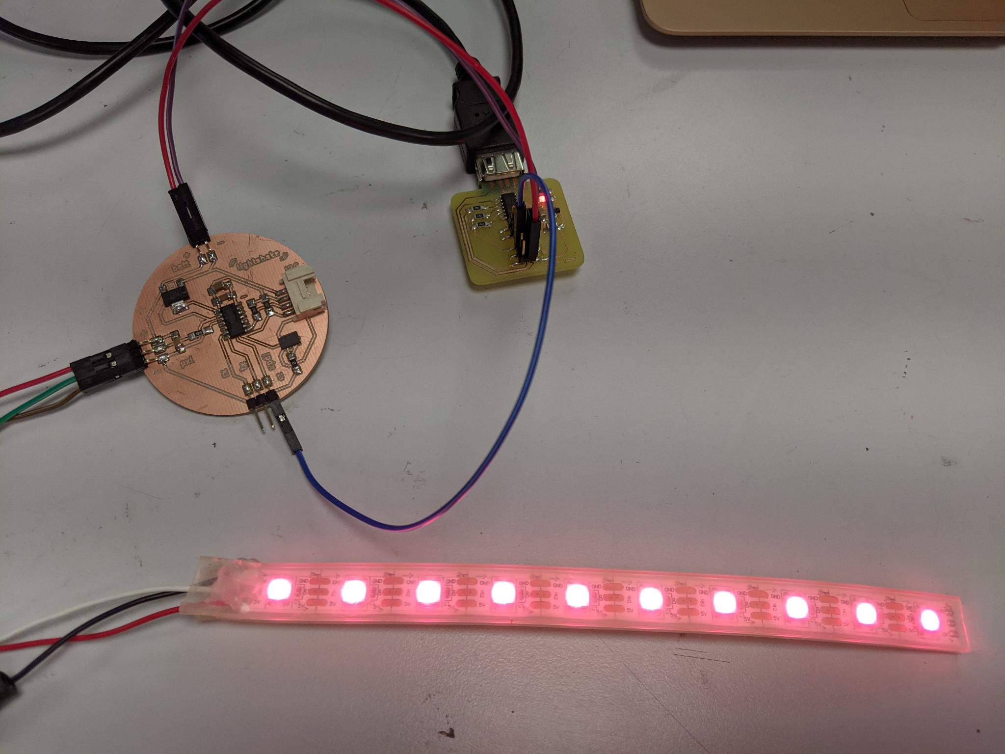
I slightly adapted this example code to trigger the fact that a neopixel strip connected to port PA5 will light up if in two particular orientations ("Landscape Left Front" and "Landscape Right Front").
    case MMA8451_PL_LRF:
      Serial.println("Landscape Right Front");
      for (int i = 0; i < NUMPIXELS; i++) {
        // pixels.Color takes RGB values, from 0,0,0 up to 255,255,255
        strip.setPixelColor(i, strip.Color(r, g, b)); // Moderately bright green color.
        strip.show(); // This sends the updated pixel color to the hardware.
        delay(delayval); // Delay for a period of time (in milliseconds).
      }
Here's a short video demonstrating this example:
Getting familiar with the axis informations
I wanted to detect significative movement, such as when one shakes the accelerometer. I started by detecting siginficative variations along the x-axis by introducing x1 and x2 which are two measures of x delayed by a few milliseconds. I thus calculate the difference dx. The value of dx will trigger specific actions if above a certain value:
  float x1;
  float x2;
  float dx;
  mma.read();
  sensors_event_t event;
  mma.getEvent(&event);
  x1 = event.acceleration.x;
  delay (50);
  mma.read();
  mma.getEvent(&event);
  x2 = event.acceleration.x;
  delay (50);
  dx = x1-x2;
Here's what we have when we ask to print x1, x2 and dx and sets a minimum absolute value of 2 to print a message "accelerates on x"
Here's the full code that lights up the led strip when significant change on x-axis is detected:
#include <Wire.h>
#include <Adafruit_MMA8451.h>
#include <Adafruit_Sensor.h>
#include <tinyNeoPixel.h>

#define STRIP           1 // PA5 on lightshake
#define NUMPIXELS      10

tinyNeoPixel strip = tinyNeoPixel(NUMPIXELS, STRIP, NEO_GRBW + NEO_KHZ800);
int delayval = 50;

Adafruit_MMA8451 mma = Adafruit_MMA8451();

void setup(void) {

  strip.begin(); // This initializes the NeoPixel library.
  strip.clear();
  delay(delayval); // Delay for a period of time (in milliseconds).

  Serial.begin(9600);
  Serial.println("Adafruit MMA8451 test!");

  if (! mma.begin()) {
    Serial.println("Couldnt start");
    while (1);
  }
  Serial.println("MMA8451 found!");

  mma.setRange(MMA8451_RANGE_2_G);

  Serial.print("Range = "); Serial.print(2 << mma.getRange());
  Serial.println("G");

}

void loop() {
  mma.read();
  sensors_event_t event;
  mma.getEvent(&event);
  //uint8_t o = mma.getOrientation();
  float x1;
  float x2;
  float dx;

  x1 = event.acceleration.x;
  Serial.print("x1 : \t"); Serial.print(x1); Serial.print("\t");
  delay (50);
  mma.read();
  mma.getEvent(&event);
  x2 = event.acceleration.x;
  Serial.print("x2 : \t"); Serial.print(x2); Serial.print("\t");
  delay (50);
  dx = x1-x2;
  Serial.print("dx : \t"); Serial.print(dx); Serial.print("\t");

  if (abs(dx)>=2){
    Serial.print("accelerates on x");
    turnOnAllStrip(255,0,0);
    }

  else {
    turnOffAllStrip();
  }
  Serial.println();
  delay(500);

}

void turnOnAllStrip(int r, int g, int b){
  for (int i=0;i<NUMPIXELS;i=i+1){
  strip.setPixelColor(i, strip.Color(r, g, b));
  strip.show();
  delay(delayval);
}
delay(1000);
}

void turnOffAllStrip(){
  for (int i=0;i<NUMPIXELS;i=i+1){
  strip.setPixelColor(i, strip.Color(0, 0, 0));
  strip.show();
}
}
And here's a code to detect significant change on all three axis.
- The led strip turns red when there's a significant change on the x-axis (
abs(dx)>10) - The led strip turns green when there's a significant change on the y-axis (
abs(dy)>10) - The led strip turns blue when there's a significant change on the z-axis (
abs(dx)>10)
#include <Wire.h>
#include <Adafruit_MMA8451.h>
#include <Adafruit_Sensor.h>
#include <tinyNeoPixel.h>

#define STRIP           1 // PA5 on lightshake
#define NUMPIXELS      10

tinyNeoPixel strip = tinyNeoPixel(NUMPIXELS, STRIP, NEO_GRBW + NEO_KHZ800);
int delayval = 50;

Adafruit_MMA8451 mma = Adafruit_MMA8451();

void setup(void) {

  strip.begin(); // This initializes the NeoPixel library.
  strip.clear();
  delay(delayval); // Delay for a period of time (in milliseconds).

  Serial.begin(9600);
  Serial.println("Adafruit MMA8451 test!");

  if (! mma.begin()) {
    Serial.println("Couldnt start");
    while (1);
  }
  Serial.println("MMA8451 found!");

  mma.setRange(MMA8451_RANGE_2_G);

  Serial.print("Range = "); Serial.print(2 << mma.getRange());
  Serial.println("G");

}

void loop() {
  mma.read();
  sensors_event_t event;
  mma.getEvent(&event);
  //uint8_t o = mma.getOrientation();
  float x1;
  float x2;
  float dx;

  float y1;
  float y2;
  float dy;

  float z1;
  float z2;
  float dz;

  int dx_trig = 10;
  int dy_trig = 10;
  int dz_trig = 10;

  x1 = event.acceleration.x;
  y1 = event.acceleration.y;
  z1 = event.acceleration.z;

  Serial.print("x1 : \t"); Serial.print(x1); Serial.print("\t");
  Serial.print("y1 : \t"); Serial.print(y1); Serial.print("\t");
  Serial.print("z1 : \t"); Serial.print(z1); Serial.print("\t");

  delay (50);

  mma.read();
  mma.getEvent(&event);

  x2 = event.acceleration.x;
  y2 = event.acceleration.y;
  z2 = event.acceleration.z;

  Serial.print("x2 : \t"); Serial.print(x2); Serial.print("\t");
  Serial.print("y2 : \t"); Serial.print(y2); Serial.print("\t");
  Serial.print("z2 : \t"); Serial.print(z2); Serial.print("\t");

  delay (50);

  dx = x1-x2;
  dy = y1-y2;
  dz = z1-z2;

  Serial.print("dx : \t"); Serial.print(dx); Serial.print("\t");
  Serial.print("dy : \t"); Serial.print(dy); Serial.print("\t");
  Serial.print("dz : \t"); Serial.print(dz); Serial.print("\t");

  if (abs(dx)>=dx_trig){
    Serial.print("accelerates on x");
    turnOnAllStrip(255,0,0);
    }

  if (abs(dy)>=dy_trig){
    Serial.print("accelerates on y");
    turnOnAllStrip(0,255,0);
    }

  if (abs(dz)>=dz_trig){
    Serial.print("accelerates on z");
    turnOnAllStrip(0,0,255);
    }

  else if (abs(dx)<=dx_trig && abs(dy)<=dy_trig & abs(dz)<=dz_trig){
    turnOffAllStrip();
  }
  Serial.println();
  delay(500);

}

void turnOnAllStrip(int r, int g, int b){
  for (int i=0;i<NUMPIXELS;i=i+1){
  strip.setPixelColor(i, strip.Color(r, g, b));
  strip.show();
  delay(delayval);
}
delay(1000);
}

void turnOffAllStrip(){
  for (int i=0;i<NUMPIXELS;i=i+1){
  strip.setPixelColor(i, strip.Color(0, 0, 0));
  strip.show();
}
}
On the following videos you can see x-axis acceleration variations in red, y-axis in green and z-axis in blue (second video):
Demo circuit with led strip
For my application I don't really care about which axis presents a significant change and rather want to detect a shaking movement. I'll have two different colors at the two ends of my strip and I want to blend the two colors when I shake the led tube
Color coding
I didn't succeed from the first attempt to have a nice color gradient, as I was introducing too many parameters comparing RGB values of one tip and the other.
One of the attempt:
The formula was in fact way simpler. Let's say that the initial state of the led strip is given by:
  strip.setPixelColor(0, strip.Color(rA, gA, bA));
  strip.setPixelColor(NUMPIXELS-1, strip.Color(rB, gB, bB));
  strip.show();
Finally the way to have a nice gradient is this piece of code:
 int r; int g; int b;
    int p = 1;

    for (int i=1;i<NUMPIXELS-1;i=i+1)
      {
      r = rA + p*(rB-rA)/NUMPIXELS;
      g = gA + p*(gB-gA)/NUMPIXELS;
      b = bB + p*(bB-bA)/NUMPIXELS;

      strip.setPixelColor(i, strip.Color(r, g, b));
      strip.show();
      p=p+1;
     }
Here's a picture of a successfull gradient:
Code
The whole code with serial prints to check everything is fine is the following:
#include <Wire.h>
#include <Adafruit_MMA8451.h>
#include <Adafruit_Sensor.h>
#include <tinyNeoPixel.h>

#define STRIP           1 // PA5 on lightshake
#define NUMPIXELS      10

tinyNeoPixel strip = tinyNeoPixel(NUMPIXELS, STRIP, NEO_GRBW + NEO_KHZ800);
int delayval = 50;

int rA = 220; int gA = 30; int bA = 20;
int rB = 120; int gB = 80; int bB = 10;

Adafruit_MMA8451 mma = Adafruit_MMA8451();

void setup(void) {

  strip.begin(); // This initializes the NeoPixel library.
  strip.clear();

  Serial.begin(9600);
  Serial.println("Adafruit MMA8451 test!");

  if (! mma.begin()) {
    Serial.println("Couldnt start");
    while (1);
  }
  Serial.println("MMA8451 found!");

  mma.setRange(MMA8451_RANGE_2_G);

  Serial.print("Range = "); Serial.print(2 << mma.getRange());
  Serial.println("G");

  for (int i=1;i<NUMPIXELS-1;i=i+1){
  strip.setPixelColor(i, strip.Color(0, 0, 0));
  strip.show();
  }
  strip.setPixelColor(0, strip.Color(rA, gA, bA));
  strip.setPixelColor(NUMPIXELS-1, strip.Color(rB, gB, bB));
  strip.show();

}

void loop() {

  mma.read();
  sensors_event_t event;
  mma.getEvent(&event);
  //uint8_t o = mma.getOrientation();
  float x1;
  float x2;
  float dx;

  float y1;
  float y2;
  float dy;

  float z1;
  float z2;
  float dz;

  int dx_trig = 10;
  int dy_trig = 10;
  int dz_trig = 10;

  x1 = event.acceleration.x;
  y1 = event.acceleration.y;
  z1 = event.acceleration.z;

  Serial.print("x1 : \t"); Serial.print(x1); Serial.print("\t");
  Serial.print("y1 : \t"); Serial.print(y1); Serial.print("\t");
  Serial.print("z1 : \t"); Serial.print(z1); Serial.print("\t");

  delay (50);

  mma.read();
  mma.getEvent(&event);

  x2 = event.acceleration.x;
  y2 = event.acceleration.y;
  z2 = event.acceleration.z;

  Serial.print("x2 : \t"); Serial.print(x2); Serial.print("\t");
  Serial.print("y2 : \t"); Serial.print(y2); Serial.print("\t");
  Serial.print("z2 : \t"); Serial.print(z2); Serial.print("\t");

  delay (50);

  dx = x1-x2;
  dy = y1-y2;
  dz = z1-z2;

  Serial.print("dx : \t"); Serial.print(dx); Serial.print("\t");
  Serial.print("dy : \t"); Serial.print(dy); Serial.print("\t");
  Serial.print("dz : \t"); Serial.print(dz); Serial.print("\t");


  if ((abs(dx)>=dx_trig)||(abs(dy)>=dy_trig)||(abs(dz)>=dz_trig)){
    Serial.print("accelerates !!");
    int r; int g; int b;
    int p = 1;

    for (int i=1;i<NUMPIXELS-1;i=i+1)
      {
      r = rA + p*(rB-rA)/NUMPIXELS;
      g = gA + p*(gB-gA)/NUMPIXELS;
      b = bB + p*(bB-bA)/NUMPIXELS;

      strip.setPixelColor(i, strip.Color(r, g, b));
      strip.show();

      Serial.print("r : \t"); Serial.print(r); Serial.print("\t");
      Serial.print("g : \t"); Serial.print(g); Serial.print("\t");
      Serial.print("b : \t"); Serial.print(b); Serial.print("\t");
      Serial.print("p : \t"); Serial.print(p); Serial.print("\t");
      Serial.println();

      p=p+1;
     }
  }

  Serial.println();
  delay(500);

}
Illustrations
I achieved the simple action I wanted to: blend the colors of each tip of the led strip when I shake the accelerometer. Ultimately I will have all components attach together so the movement of the led tube will create that interaction.
Circuit before shaking:
Circuit after shaking movement:
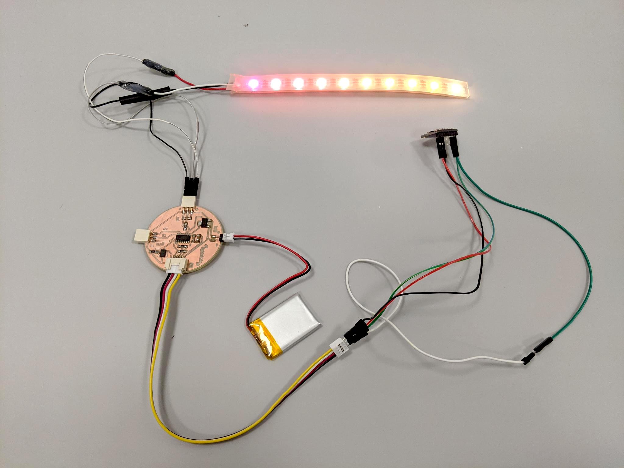
Yet another board!
In order to place the MMA8451 accelerometer directly on the circuit I redesigned my board. I also removed the ADXL343, and changed the grove for header pins. I changed the regulator for a smaller one (3.3 V 100mA and with smaller footprint).
I hand soldered it. Not working yet, stay tuned 8-)
Files
- KiCad files and gerber of the ADXL343 board (number 2)
- KiCad files and gerber of the MMA8451 board (number 3)
- Arduino file of the lightshake gradient demo
Week 12 - Molding and casting
Wax premold technique
One of the goal of this week was to get familiar with 3D milling with a CNC such as the Shopbot Buddy. We thus started by creating a premold in a molding wax block.
Premold design
Constraints
The constraints for the model were numerous:
- Width and length: you have to take in account a sufficient width of silicone that will be cast in the premold
- Height: you have to take in account the silicone mold bottom thickness, but also the depth your milling tool can go down to. It thus depends on the milling tool you choose
- Details: the size of the surface details you can achieve depends on the diameter and the shape of your milling tool.
- One side milling: You have to anticipate if your mill can go to all the surfaces, for example if they are hidden under other volumes.
- Simplicity: I decided to do a first mold in one part, with a flat surface, because time management is a big challenge for this week.
I thus decided to create a relatively flat object I could use in my final project. As my final project is about playing with light effects and shaddes, I wanted to create an incense holder to play with the fumes light effects, with a textured surface to have some nice shadings on the object.
CAD in Fusion 360
I first started to design the object itself. I got inspired by the process of the following youtube video by Kristian Laholm to design a wave panel :
Design steps
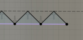
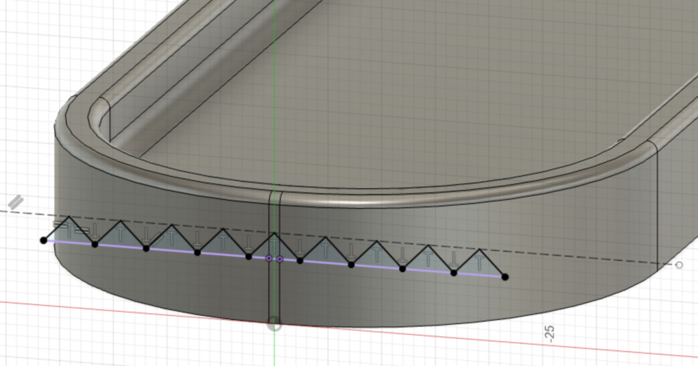
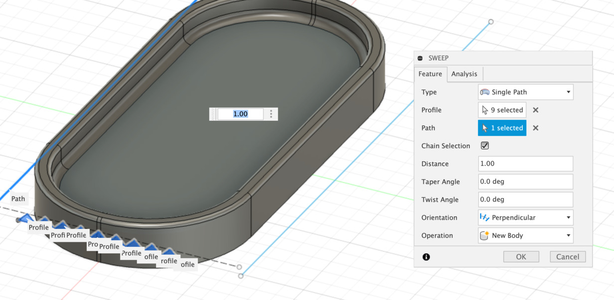
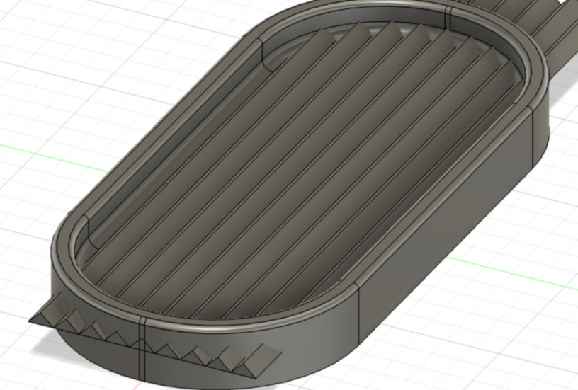
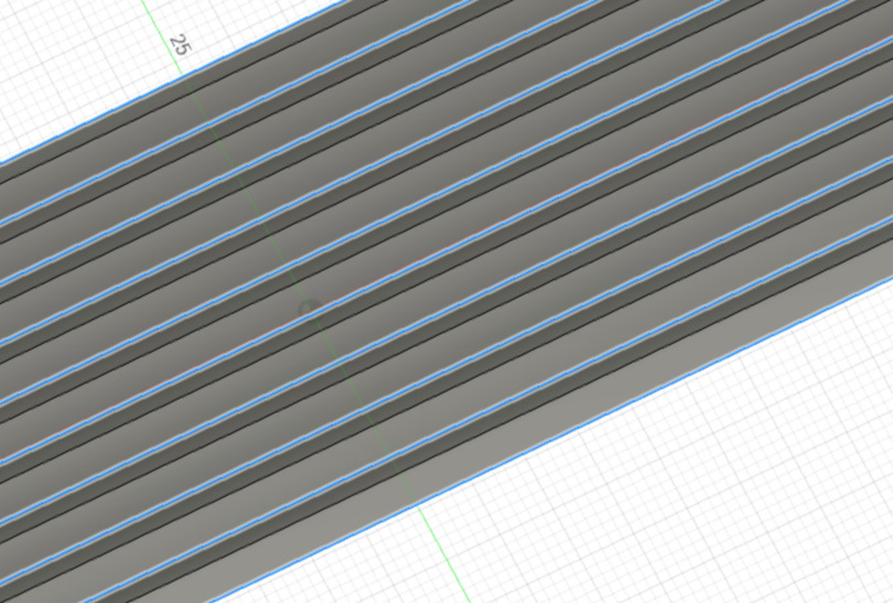
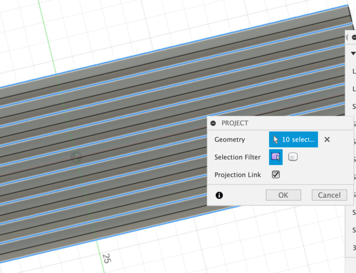
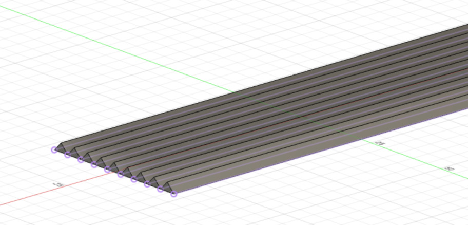
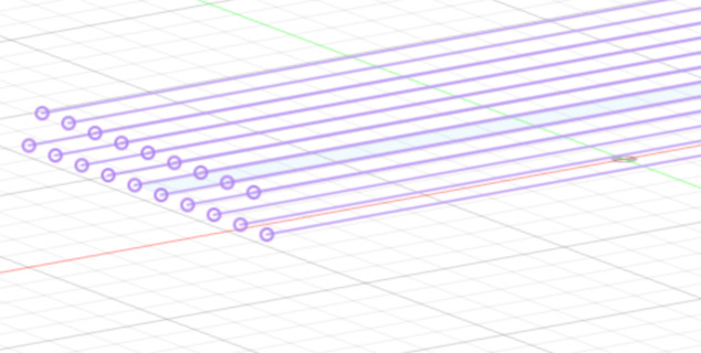
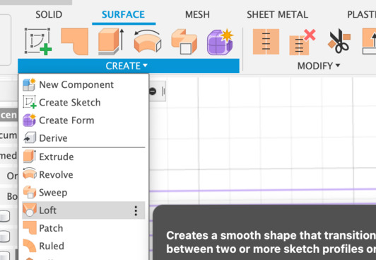
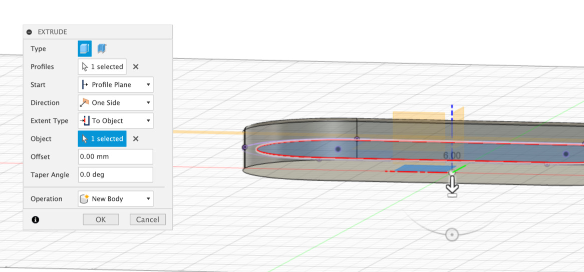
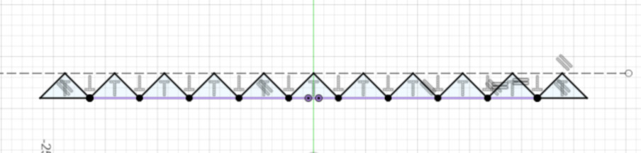
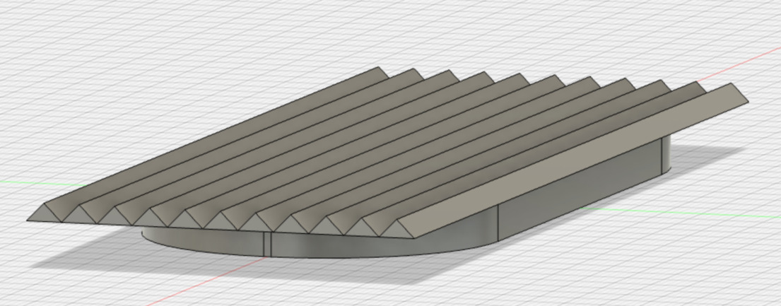
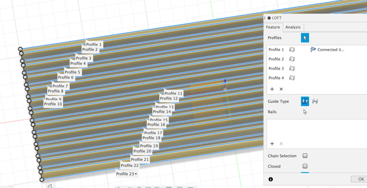
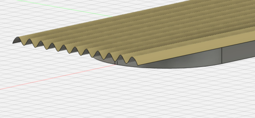
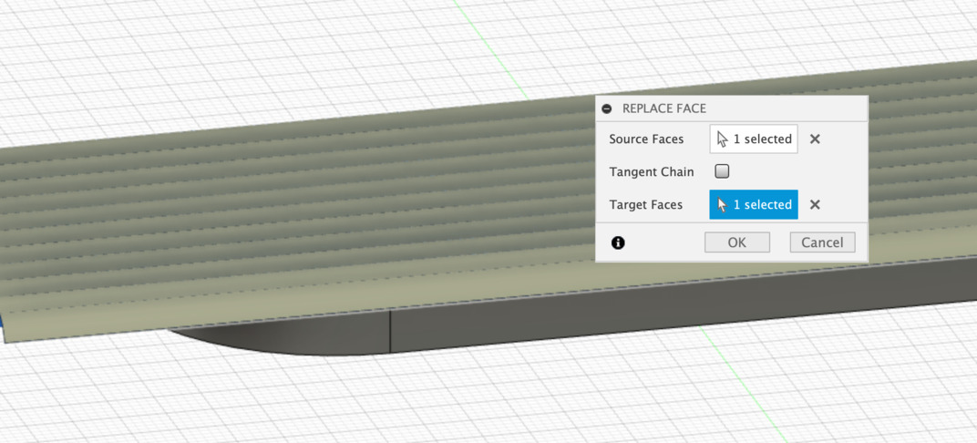
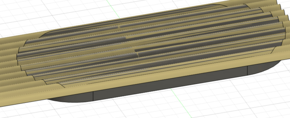
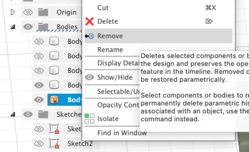
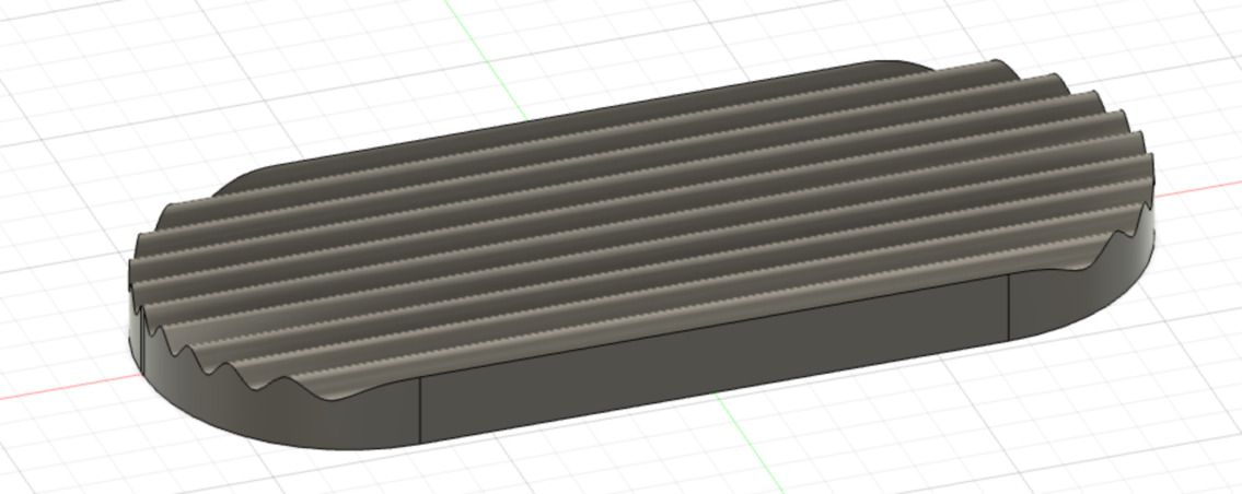
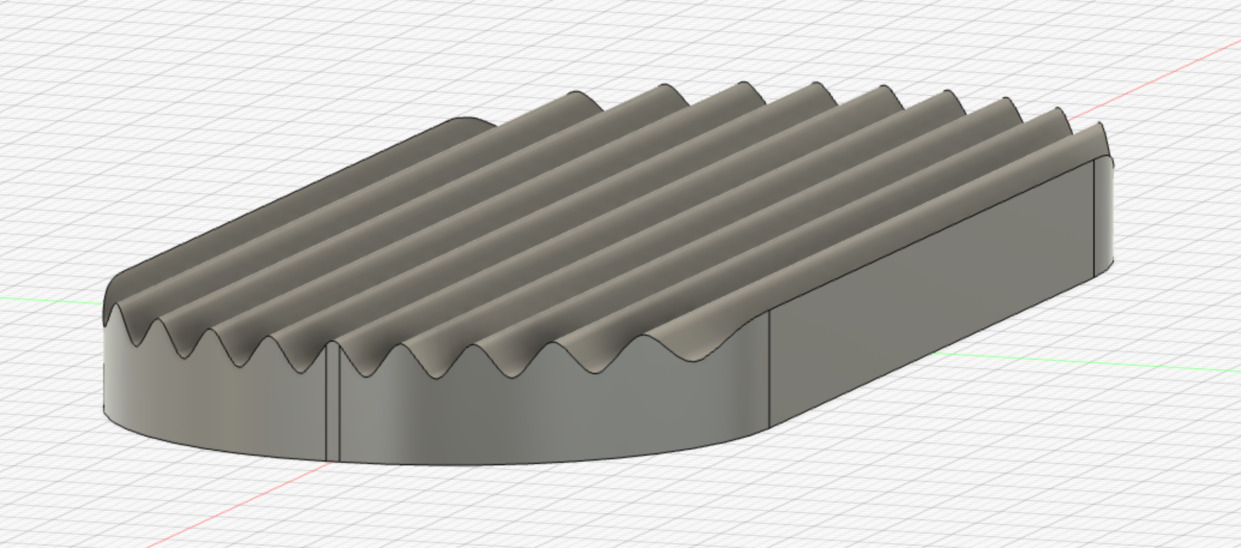
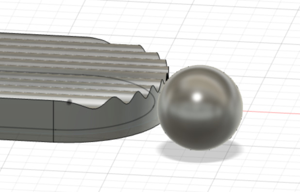
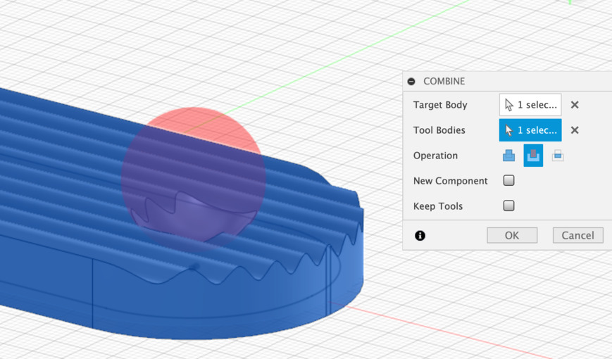
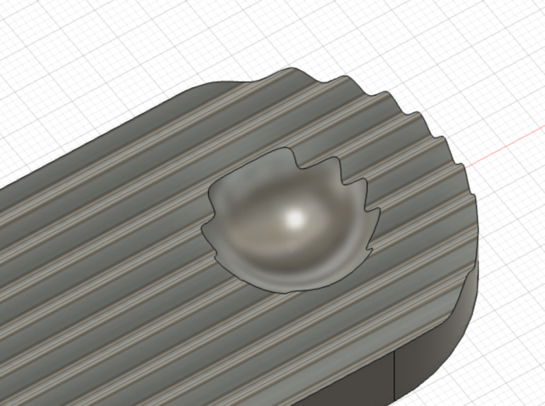
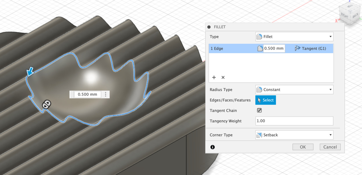
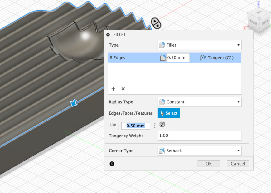
Result
The sphere will not be molded. As I imagined it it should be able to hold an incense stick while allowing to orient it according to its length. The stability will be the biggest challenge here!
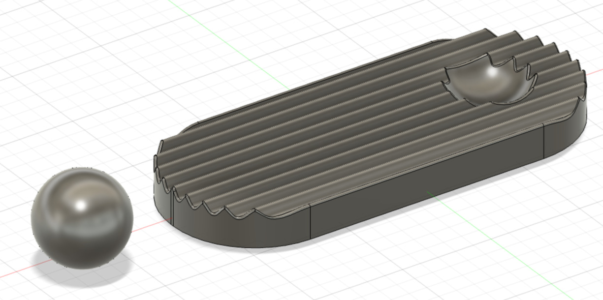
I printed in PLA (0.1mm layer height) to check that I liked the general shape.
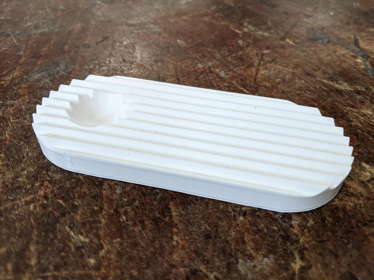
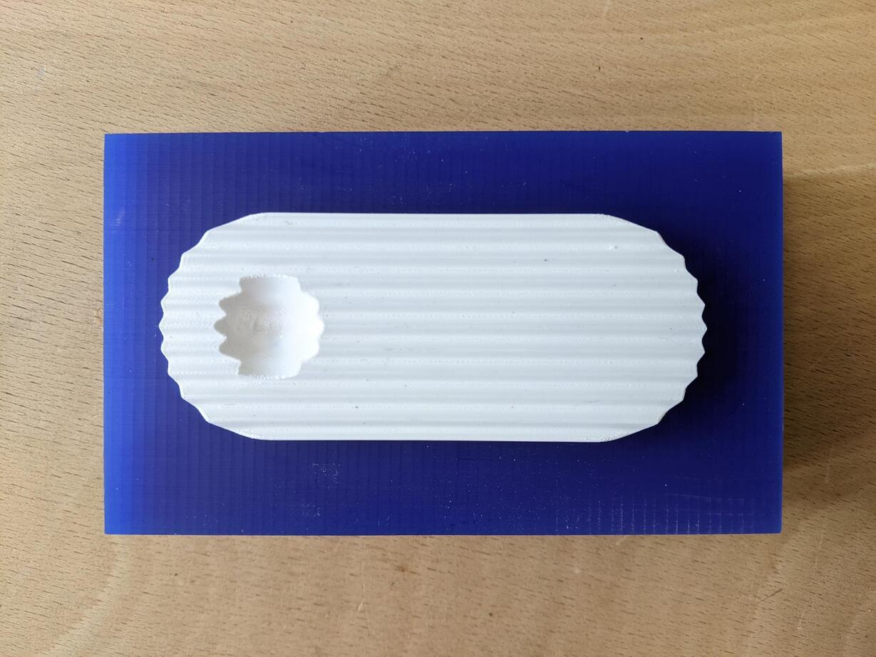
I then designed the whole enclosure by creating an outside shape withe the same of the wax block I will mill afterwards.
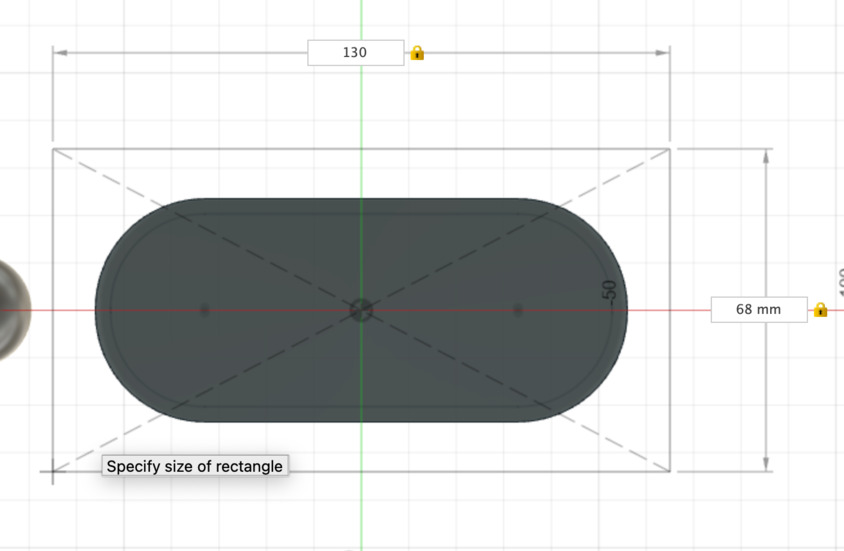
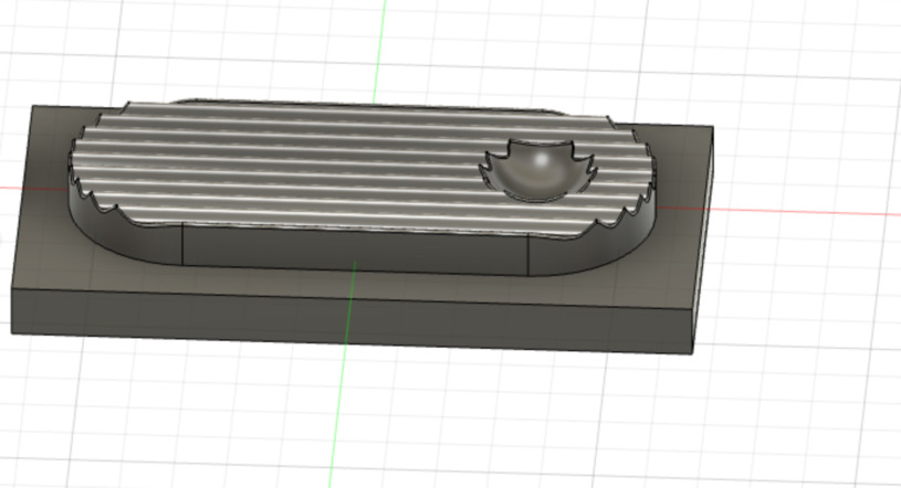
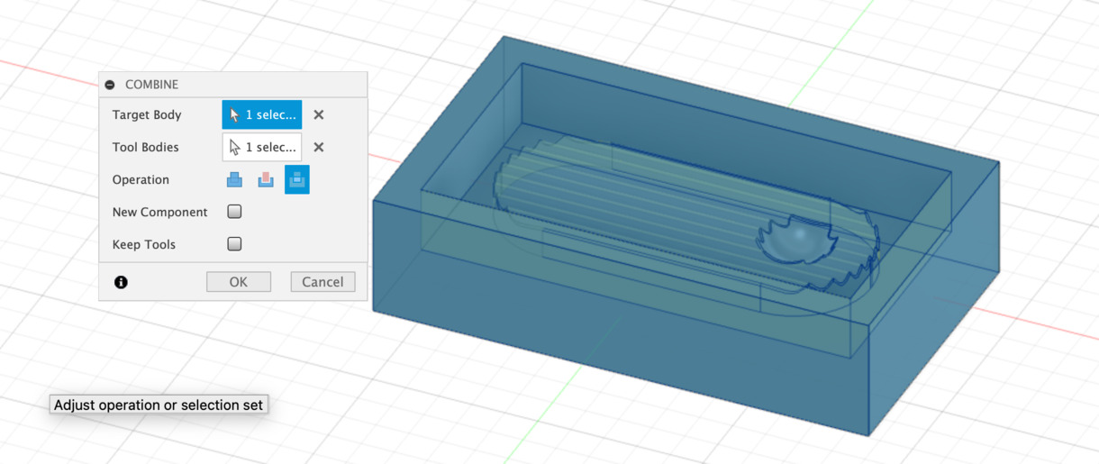
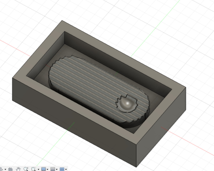
Premold milling with the Shopbpot Buddy CNC
Job preparation on VCarve
The material dimensions are those of the wax block. I selected the zero on the surface of the material. I then imported the stl model and placed it correctly in the material area.
I prepared two tasks: * one rough milling with a 6mm diameter mill * one finer milling with a 3.175 diameter rounded mill
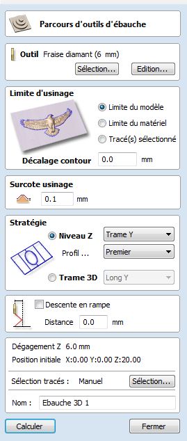
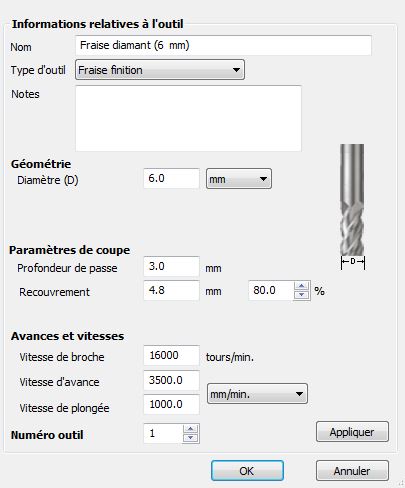
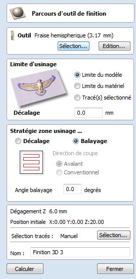
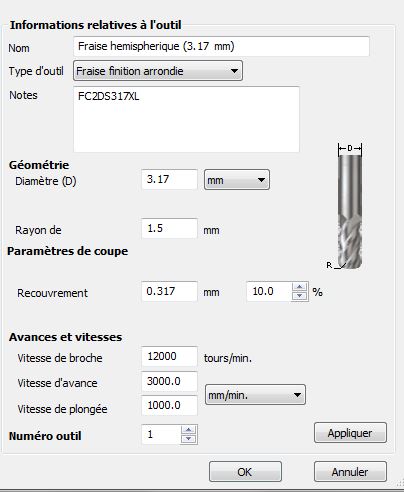
The first previsualisation gave the impression that the mill wouldn't go all the way down in the top surface creases, so I modified my design to have less and wider creases. But in fact it was because the tool was not correctly parametrized in VCarve: the diameter was correct, but I needed to indicate that it was a rounded mill. I then obtained a satisfying previsualisation.
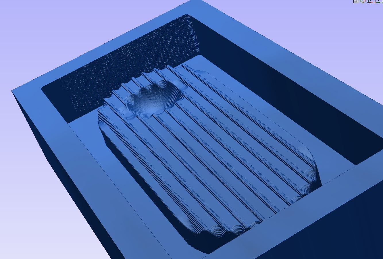
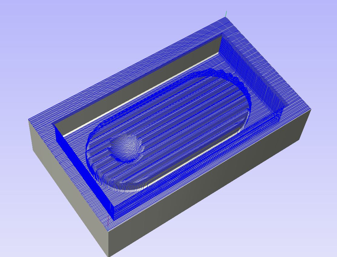
Milling
Our instructor had prepared a system to hold the wax block in place. Nevertheless it was a bit high and I couldn't do the zero properly with the metal plate like we do usually, and did the zero manually by checking visually it was perfectly touching the surface of the wax block.
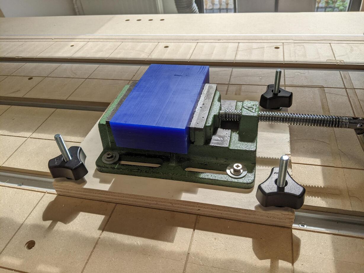
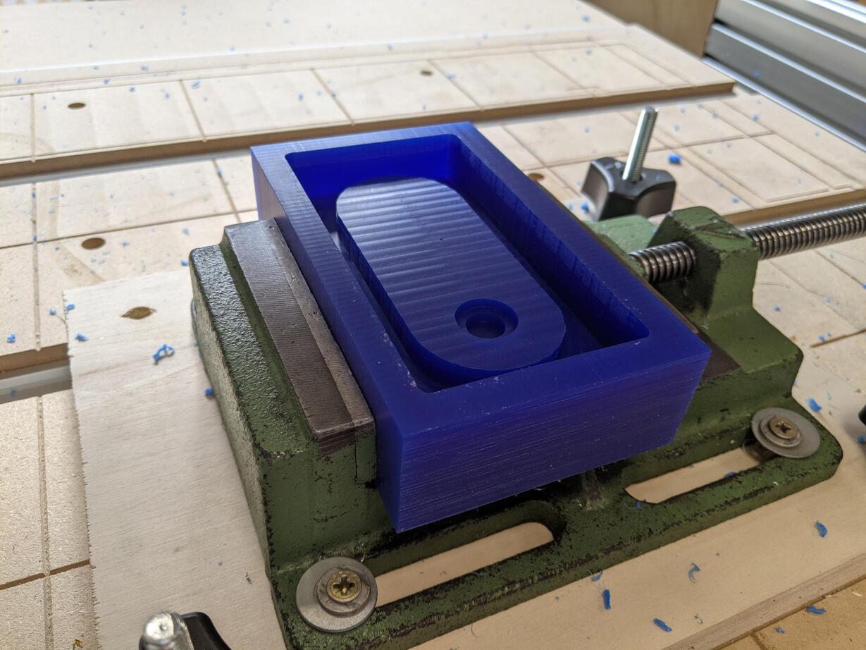
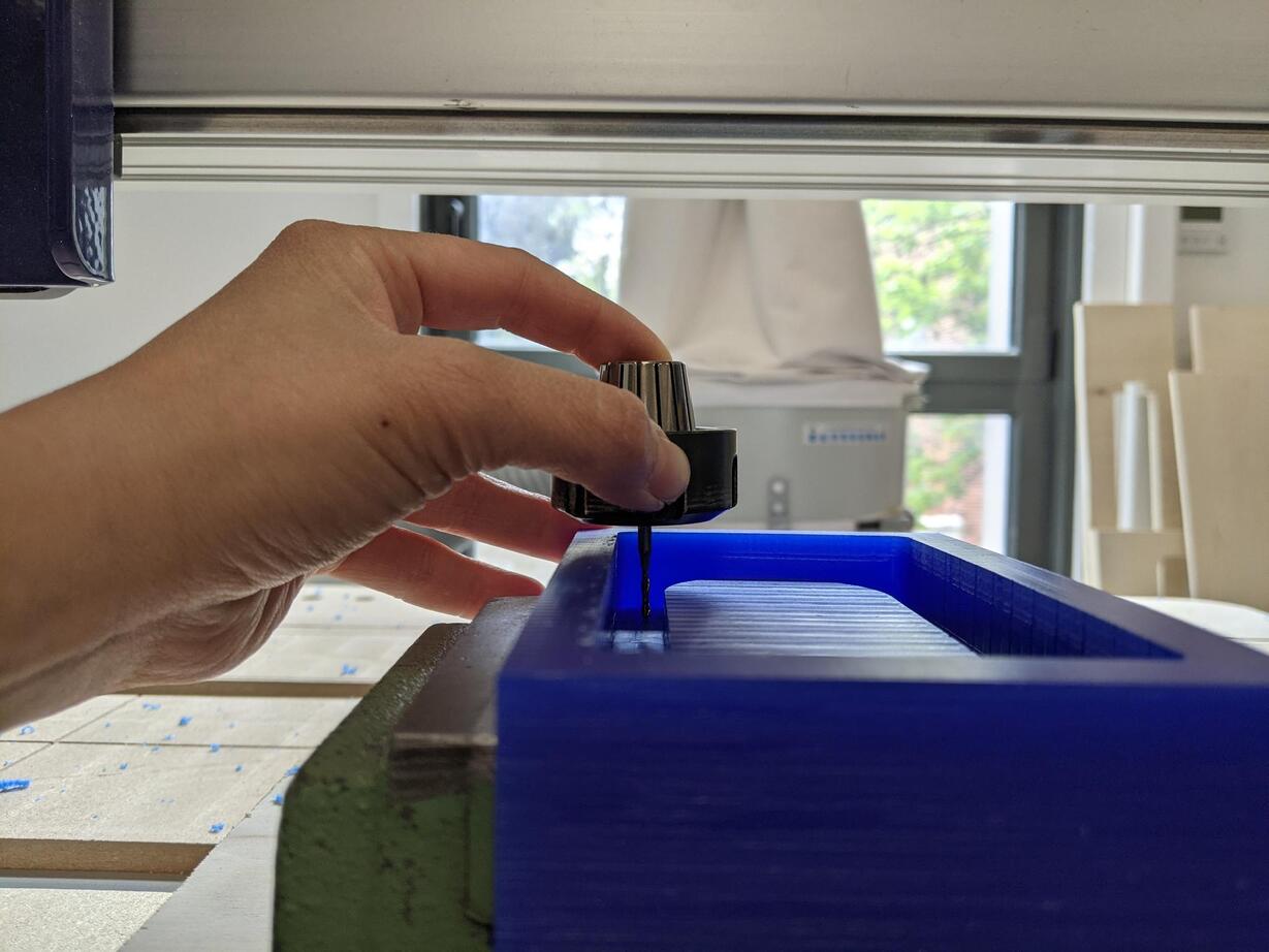
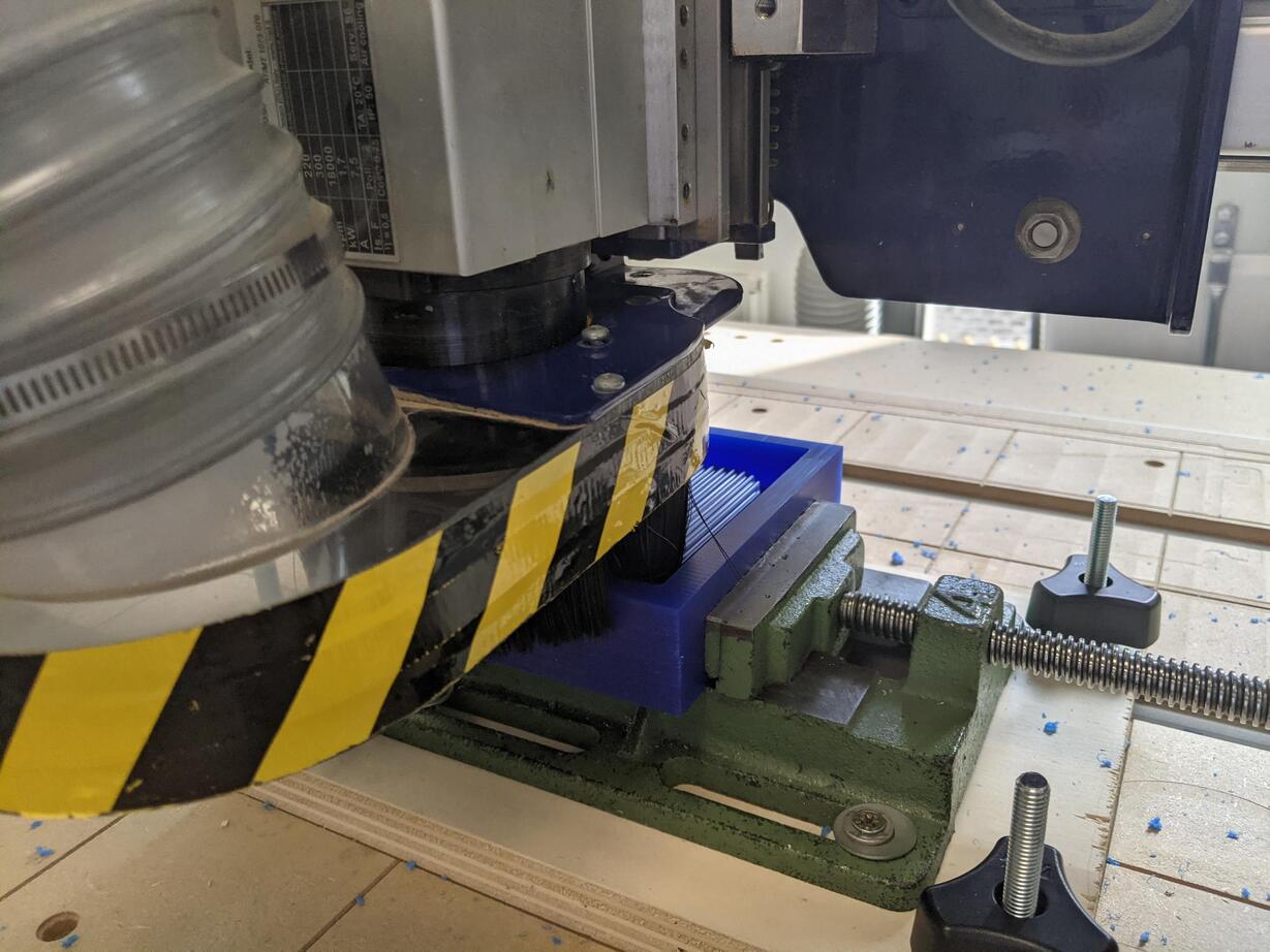
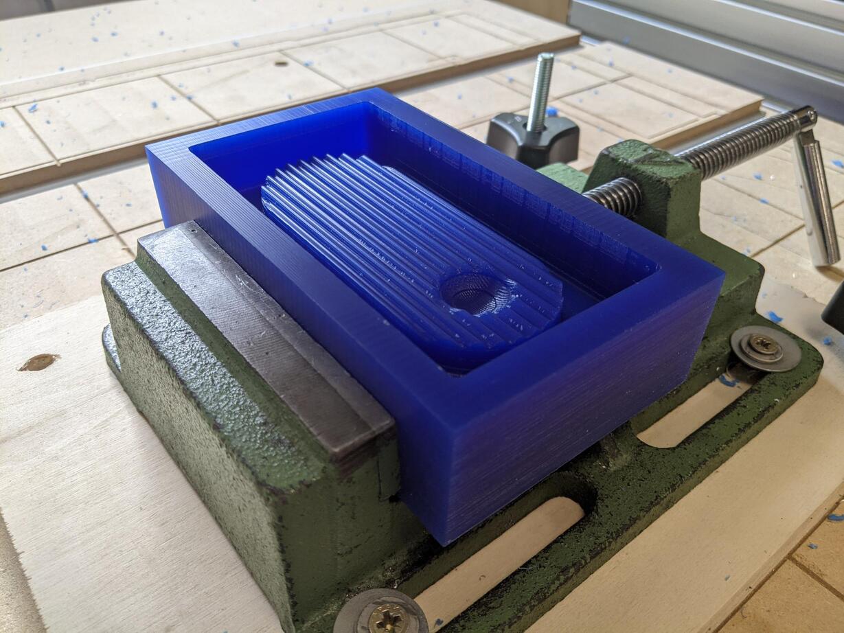
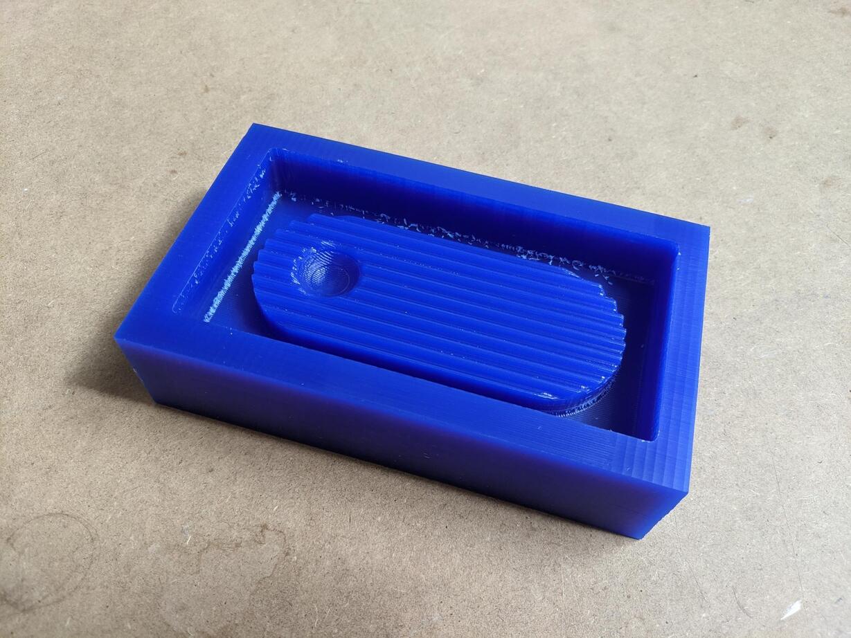
The result was overall very satisfying.
Casting the silicone mold
I then casted some silicone in the wax premold.
Material
- Silicone Part A and B
- Wax premold
- Plastic containers
- Metal spatula
- Balance
- Plastic throwable eyedropper
- Throwable latex gloves
- Tissue paper
- Ethanol if you make a mess with the liquid silicone
Steps to follow
- Weigh the silicone Part A and Part B after mixing thoroughly each part in their bottle, in the proportion indicated by the fabricant. In my case It was 5g Part B for 100g Part A.
- Mix them together very well.
- Remove the air bubbles with the vacuum pump.
- Cast it slowly in a corner of the premold in order to go directly to the bottom surface and not the details of the premold. This is to avoid creating air bubbles on details of the mold.
- Wait 16 hours before removing the silicone mold.
- Wait for the tools to dry for cleaning.
The silicone mix was very thick and not easy at all to cast! I was scared it would be a complete mess not resulting in a satisfying mold. First I thought it could be a low quality silicone, but it was probably because I forgot to shake the Part B! I probably put only the bottom of the liquid agent (since I used a throwable plastic eyedropper)
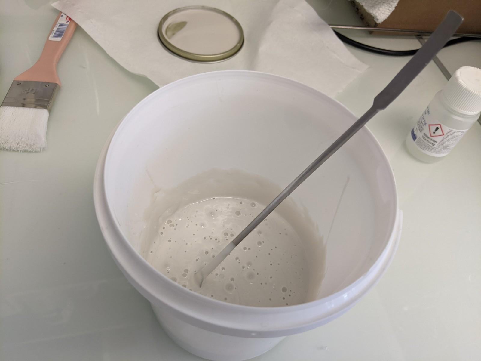
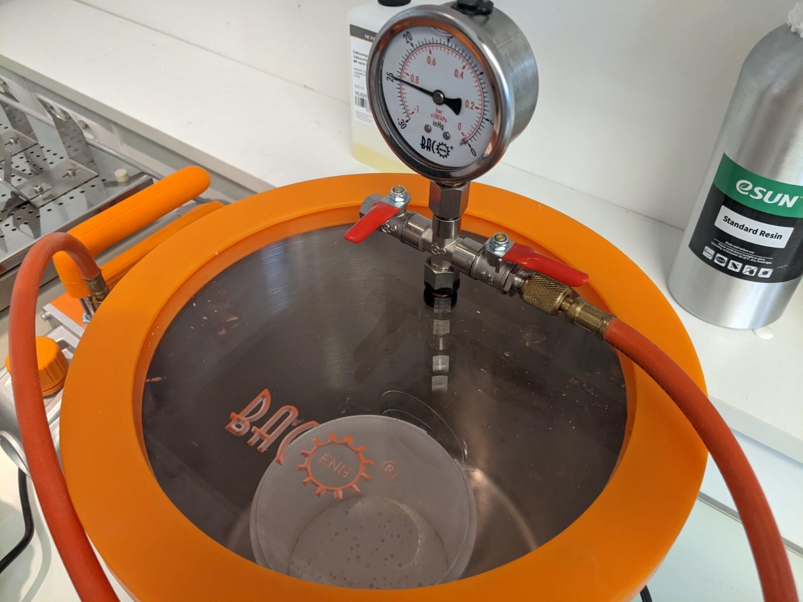
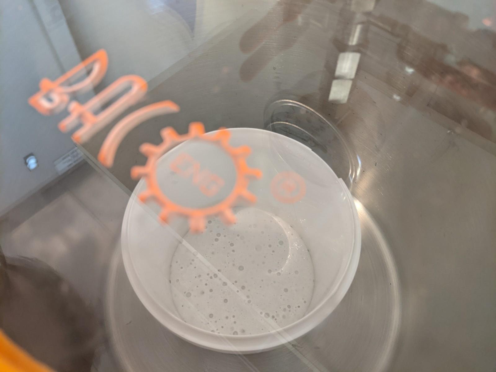
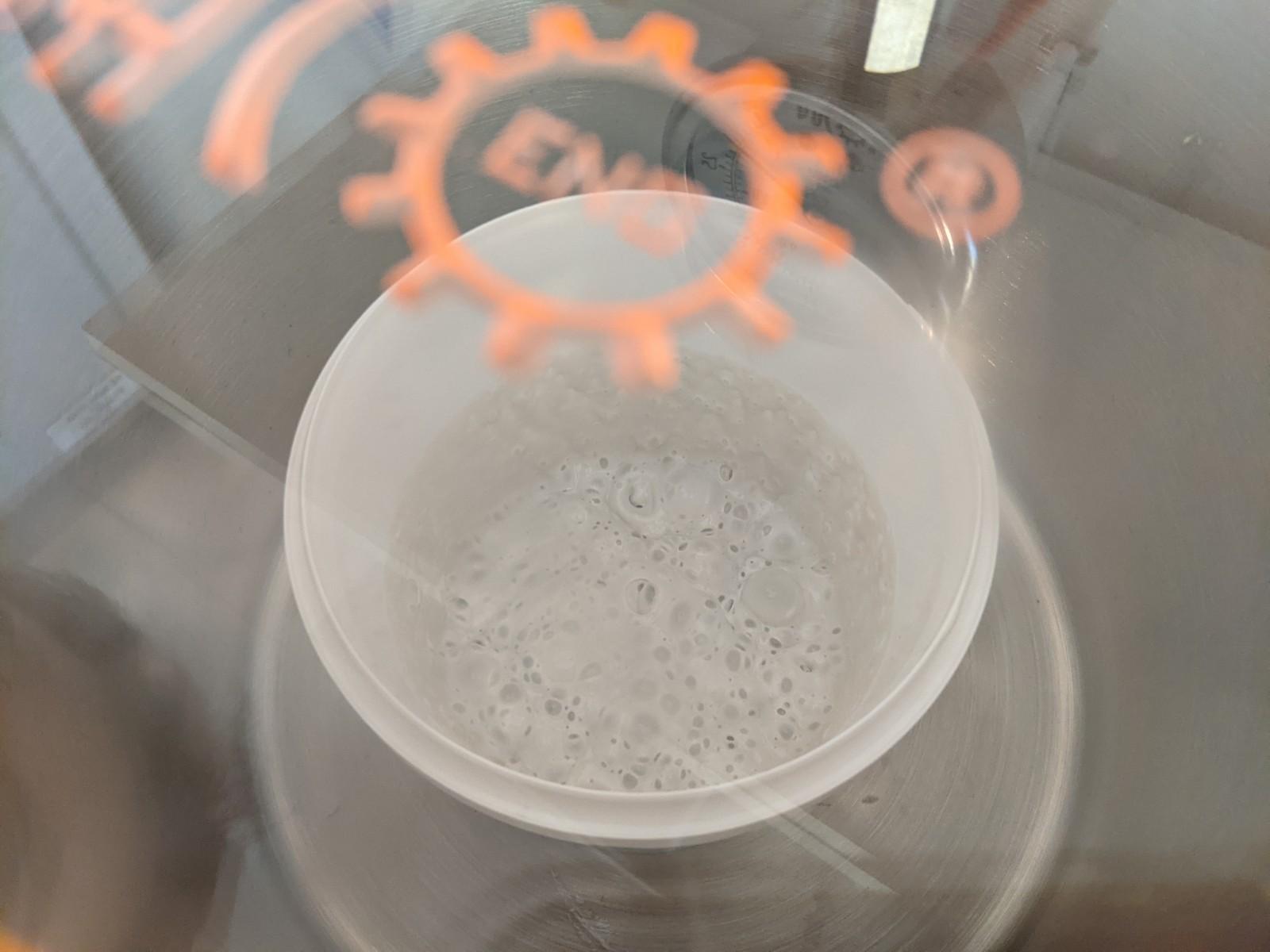
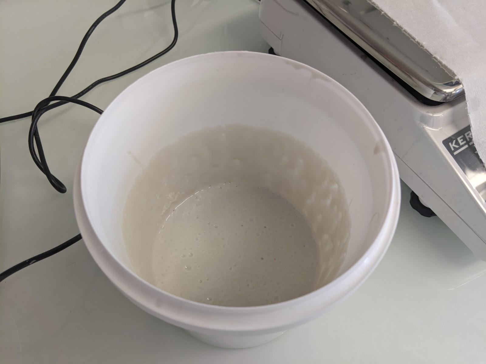
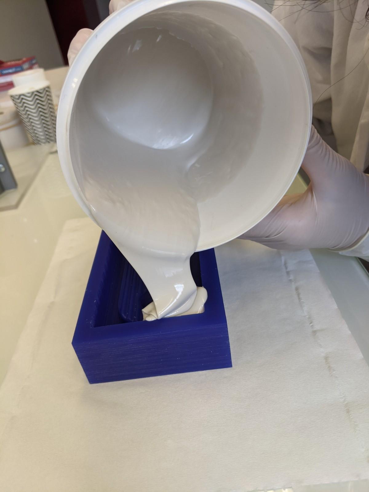
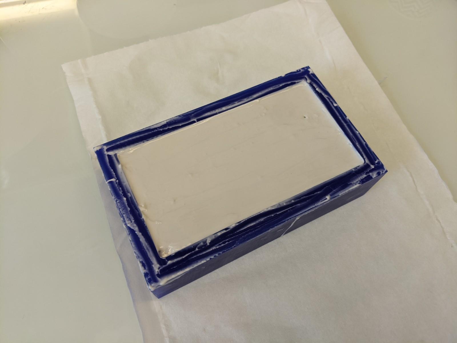
I came back to the lab two days after and in fact it worked just fine! It only had very few imperfections. To take out the silicone mold I just slowly pulled the edges of the silicone from the wax with my fingers, and it went off nicely.
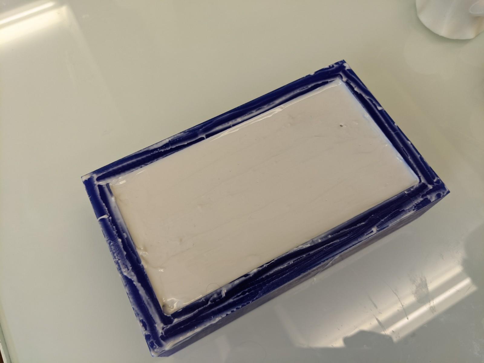
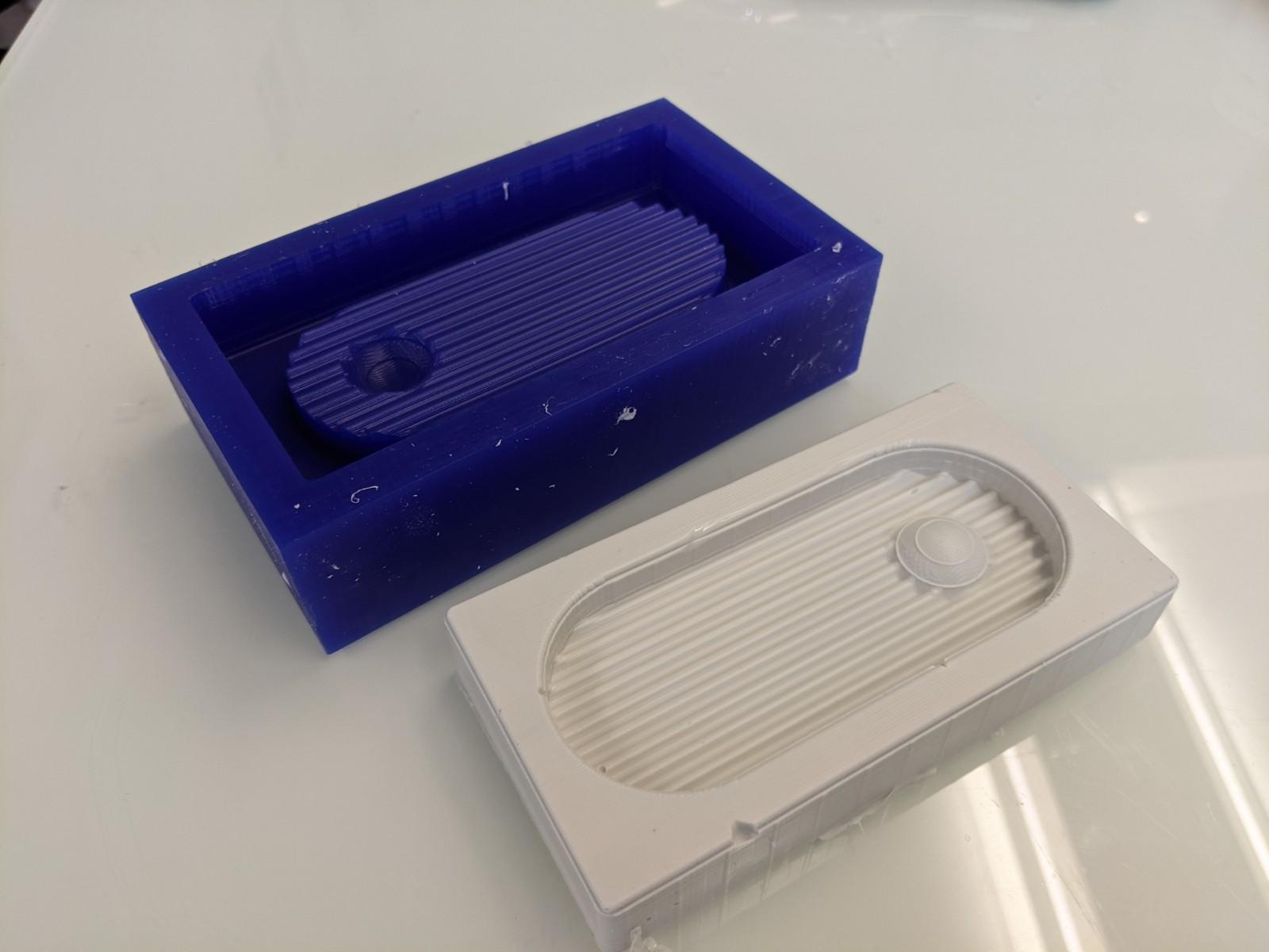
Silicone 'sock-mold' (?)
Principle
Another molding technique demonstrated by my colleague Simon is to cast silicone all around a premold inside a removable enclosure. He even made a parametric enclosure design in fusion to be adapted to various models dimensions. You need a flat surface on your model to use this technique, and you have to think that your object must be easily extracted from the silicone mold around it.
Printing the enclosure
- Open the fusion file and change the dimensions for the enclosure.
- Save as mesh
- Slice
- Print it in PLA
Making the mold
Material
- Object to model
- Parametric two parts enclosure
- Four screws and four bolts to tighten the enclosure
- Screwdriver
- Wrench
- Double-sided tape
- Piece of 3mm acrylic or similar flat surface (The one I used measures approx 15 x 25 cm)
- Silicone part A and B
- Plastic container
- Metal spatula
- Latex gloves
- Balance
- Vacuum pump
- Exacto or box cutter
- Rubber bands
- Flat spatula
Steps to follow
- If needed, design and print your model
- If needed, adjust and print your enclosure (see above)
- Tape the model to the acrylic plate with double sided tape
- Tape the enclosure to the acrylic around the model
- Screw the two parts of the enclosure together
- Try to mark the orientation of your object somehow (in order to place the slits correctly once the silicone will be solidifier, see a few steps below)
- Shake the two parts of the silicone
- Weigh them in the same containter. It shouldn't fill all the container as the mixture will double / triple volume when we will remove the air bubbles
- Mix well with the metal spatula
- Remove the air bubbles with the vacuum pump
- Cast it slowly: as usual, aim for the acrylic plate and not the surface of your object.
- You can tap the acrylic plate on the table if you want to remove eventual air bubbles
- Wait 16 hours
- When dried, separate the acrylic plate from the rest using a flat spatula
- Open the enclosure by unscrewing the four screws
- Take out the object trapped in the silicone: make some diagonal slits while stretching the silicone where you're making your cuts. The zigzag shape of the cut will allow to align better the silicone when remolding. Cut until you can release your object (maybe approx to half of the height). You can make two zig zag cuts on two opposite sides of the silicone mold. Avoid cutting them on area of your object with a lot of details
- Remove the object
I did such a mold using a ribbed column I printed months ago to make a candle but never had the opportunity to mold. I had also printed an adapted enclosure beforehand (but after some thoughts I think it's too large, which wastes some silicone).
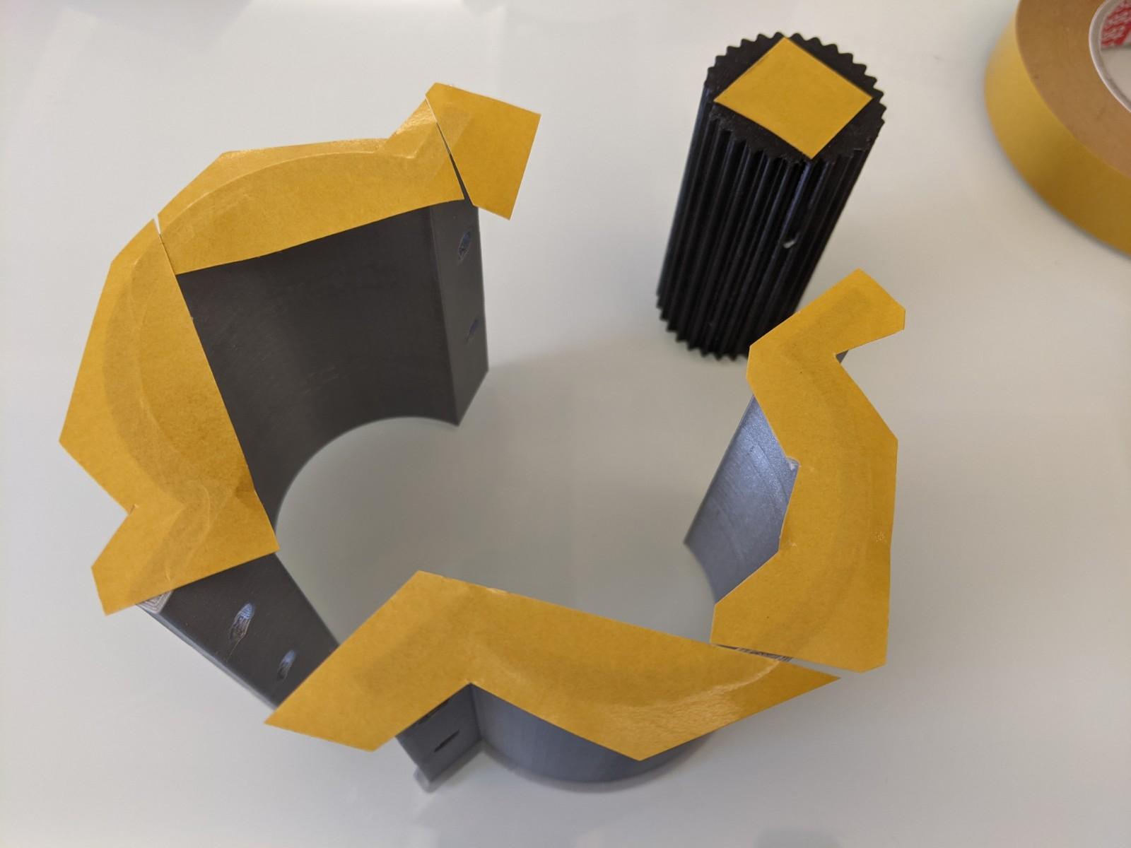
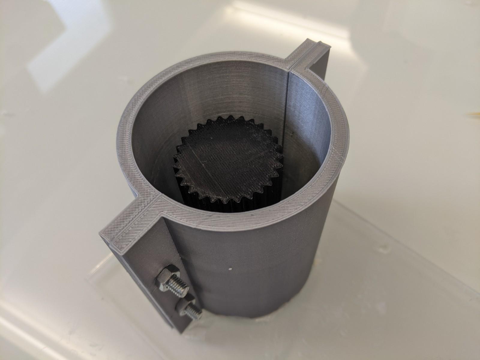
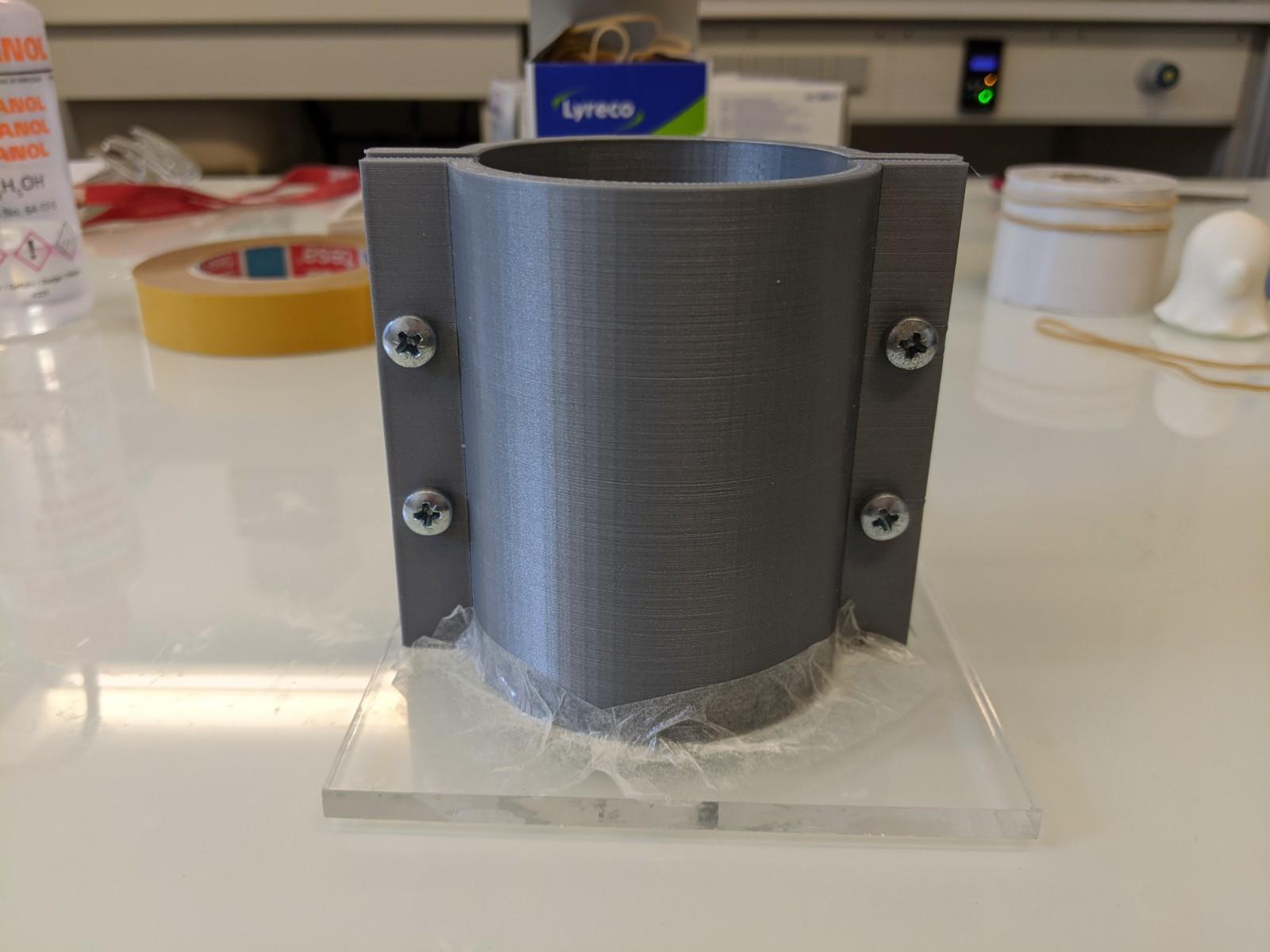
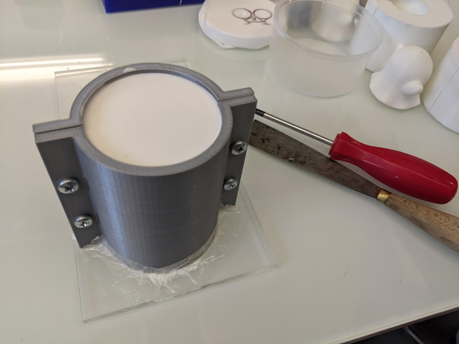
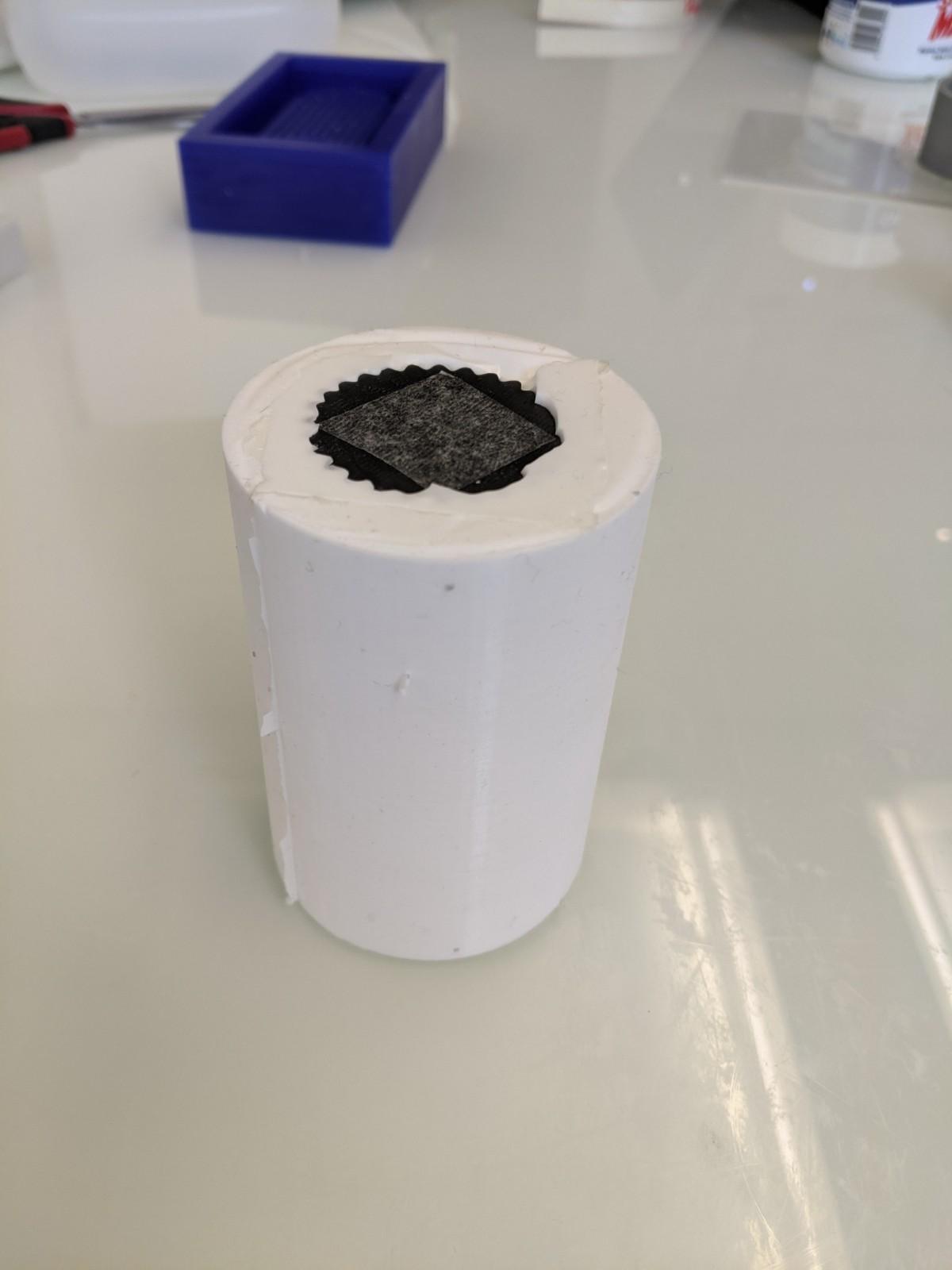
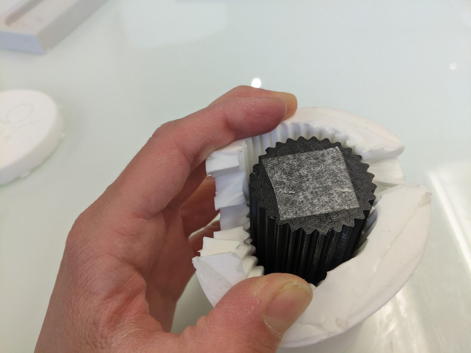
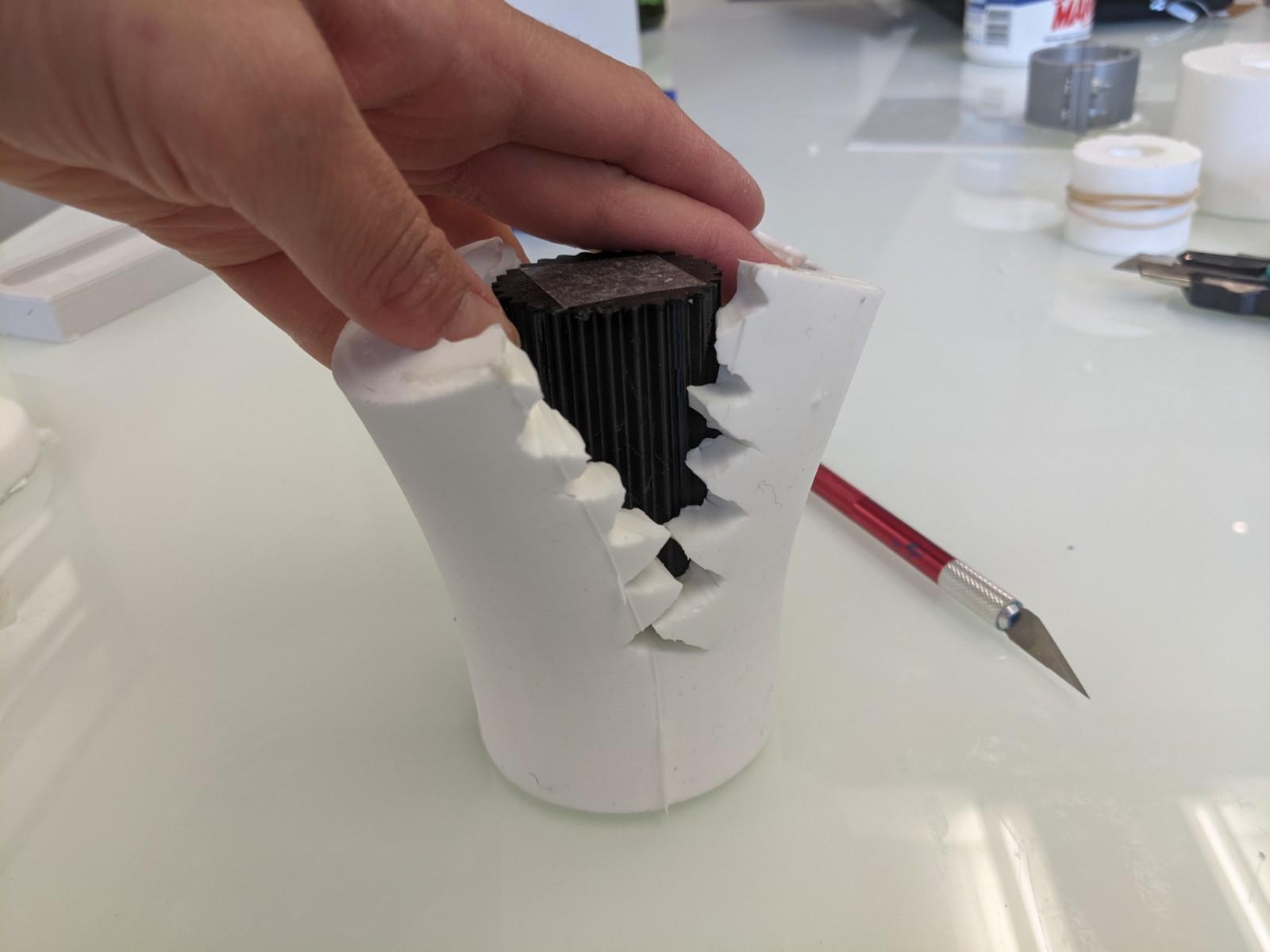
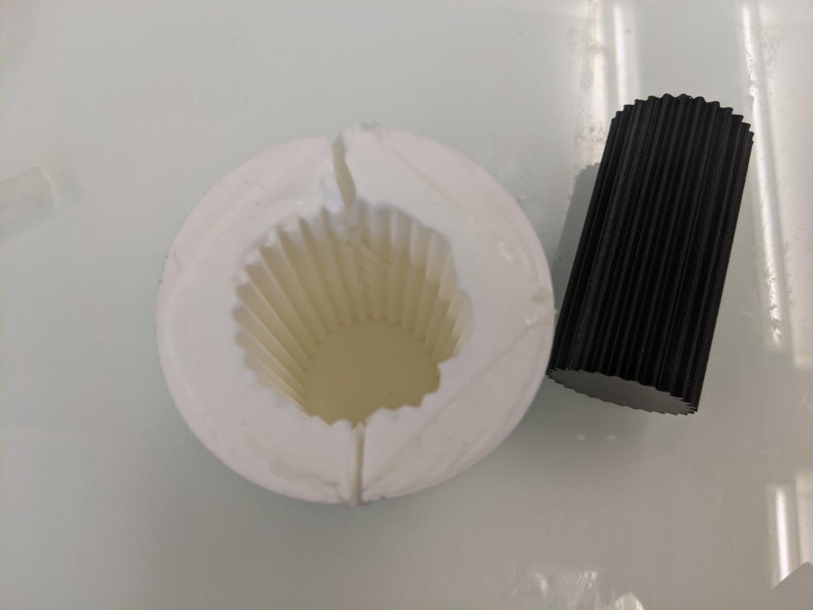
Casting in the sock mold
- Carefully align the zigzag slits
- Wrap some rubber bands to secure them tightly, but not too much!
- Cast the material and wait for it to dry
- Remove the rubber bands and carefully pull out the silicone from the molded part
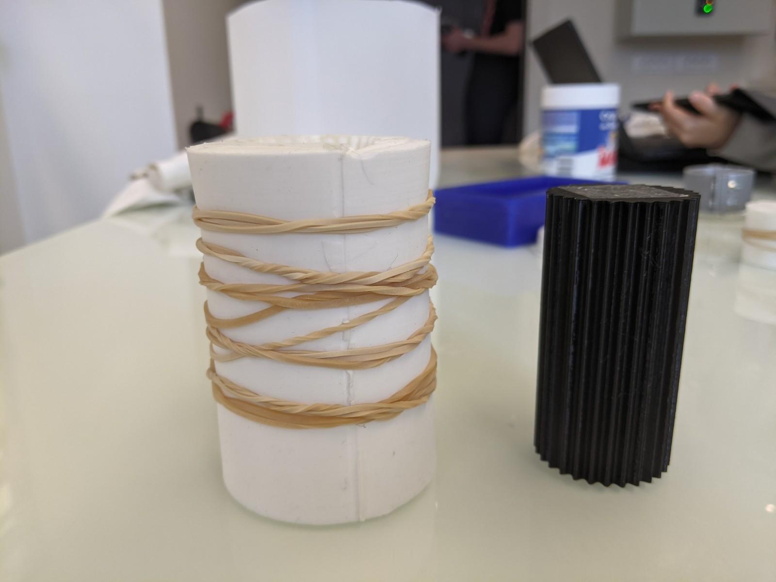 This is too tight!
Casting
I wanted to cast some rough material such as plaster or cement, but first of all started by casting polyurethane, since it's very quick to dry and easy to use. That would make a nice first test.
Casting polyurethane
Casting polyurethane is really easy. Thus you have to comply to some safety rules:
- Latex throwable gloves
- Eye protection, since it is irritating for the eyes
- Ventilated area
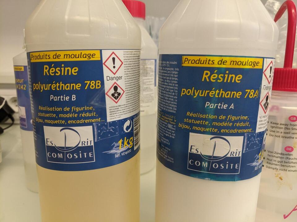

Steps to follow
- Shake well part A and part B
- Weigh them (following the instructions on the bottles for the proportions of A and B) and mix them in a throwable container (such as a paper cup or plastic tray)
- Mix them well with a metal spatula to have an homogeneous liquid
- The reaction realeses heat, as soon as it gets a bit warmer you should cast them - in a corner of the mold, slowly and consistently.
- Wait 20 minutes before demolding
The reaction happens very fast, for my first try I waited just too long (I wanted to take a picture of that step), and it solidified before I had the time to cast it, becoming a big gelified block. Unfortunately I had to throw the mix and do a new mix.
The result for the incense holder tray was quite satisfying, except some yellowish small spots. Not mixed correctly maybe?
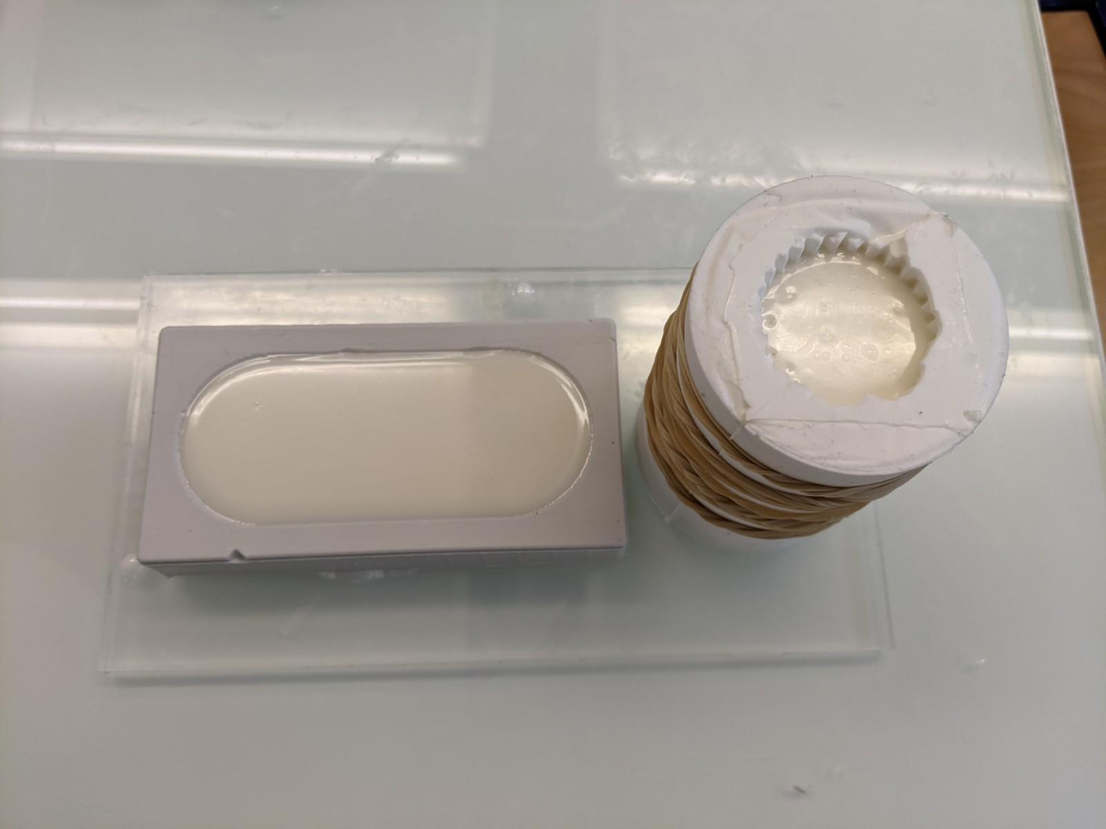
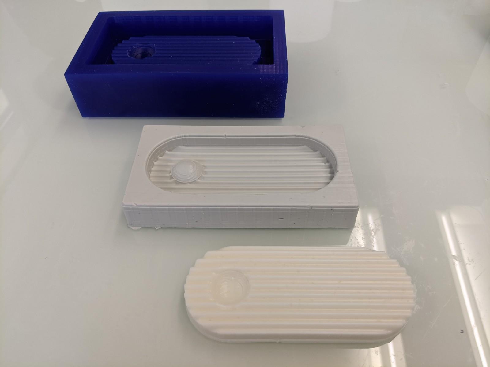
The ribbed column made in the sock-mold was deformed by the rubber bands pressure! Also the mold's slits are too visible.
Casting plaster
I asked to the paint workers on the campus if they had some construction plaster and they provided me a generous quantity of plaster powder, to be mixed with water.
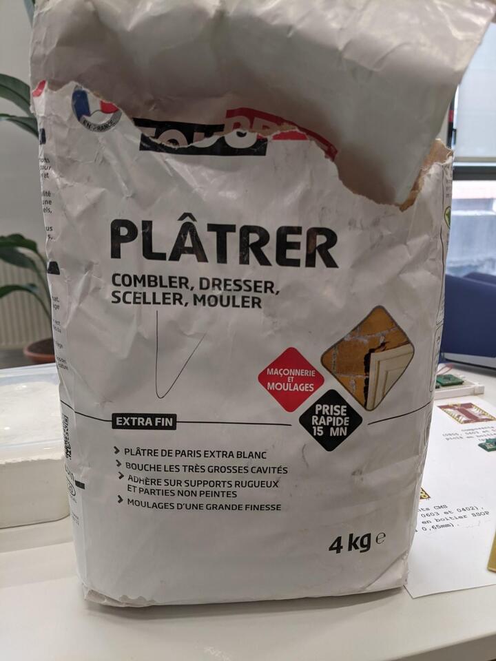
At first I followed the ratio indicated on the plaster bag, (1,5 volume plaster powder for 2 volumes water), but then progressively adjusted it to have a thicker mix. The ratio I was satisfied with was 50g plaster powder for 30g water
Material
- Plaster powder
- Silicone mold
- Throwable paper cups
- Graduated cylinder
- Metal spatula
- Balance
- Paper tissue to protect the area
- Latex gloves (I read that dry plaster can irritate the skin)
- Water
- Medium size brush
- A flat surface such as piece of 3mm acrylic
Steps to follow
- Place the silicone mold on the flat surface (here the piece of acylic)
- Protect the balance's surface with a tissue paper
- Weigh 50g of plaster in the paper cup
- Measure 30 cL of water in the graduated cylinder
- Mix them well with the metal spatula.
-
(Optional) Brush some of the mix at the bottom of the silicone mold into the details
When you mix the plaster you tend to introduce quite some air bubbles that are hard to get rid off because of the plaster's thickness. That's why I started by brushing the details on the bottom of the silicone mold for the incense tray. I then casted the plaster mix and gently tapped the acrylic plate.
-
Cast the plaster mix. You have to procede quite quickly, else it will dry and thickens.
- Remove the air bubbles by tapping the acrylic plate on the table's surface. Also you can gently tap the edges of the silicone mold to make the air bubbles go up to the surface
- Wait at least 30 minutes to demold
- The plaster can be demolded but it's not completely dried yet. It can take 24-48hours to dry completely
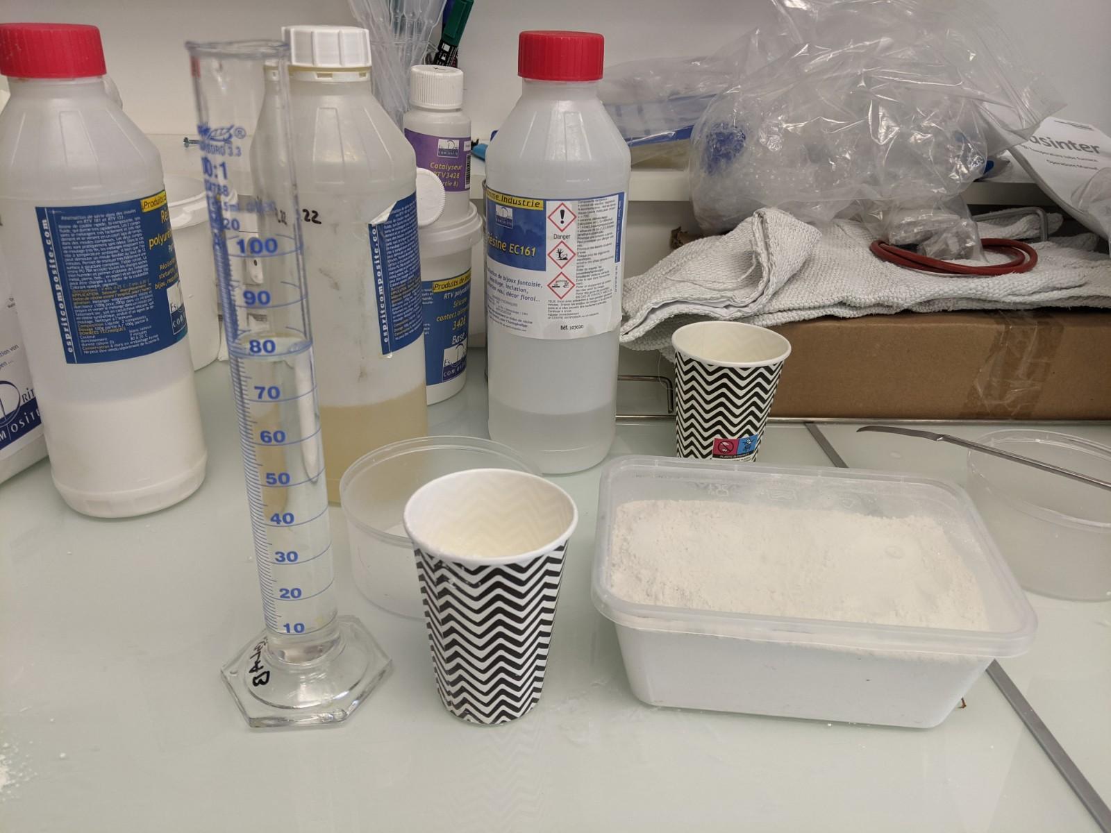
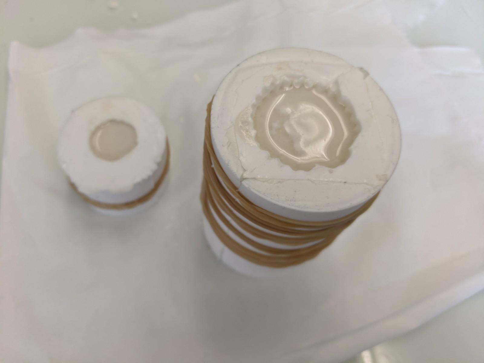
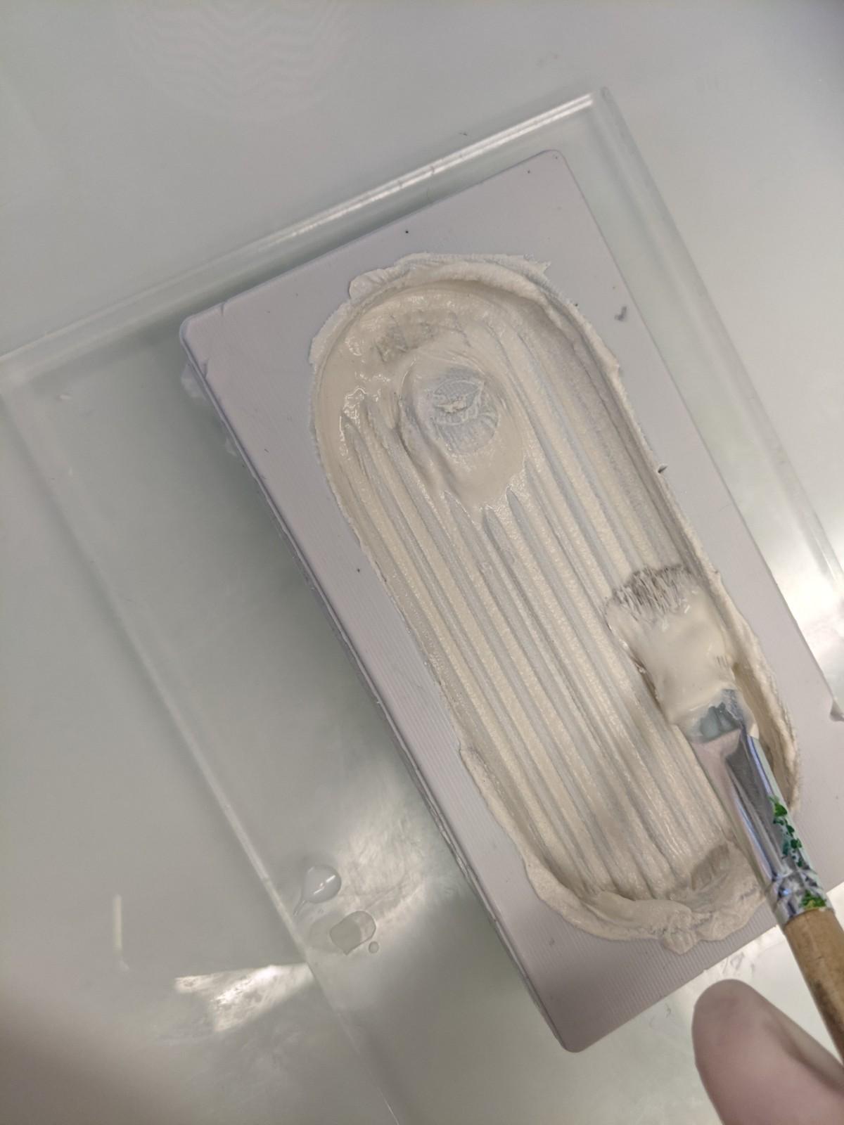
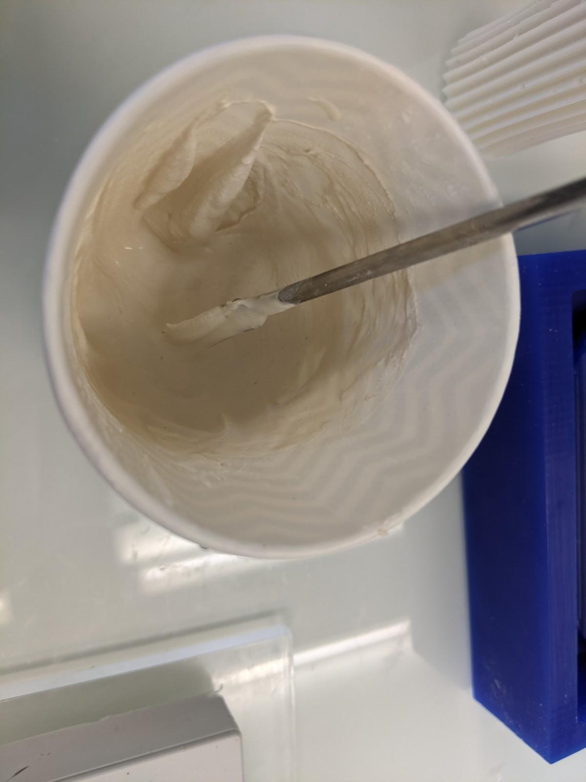
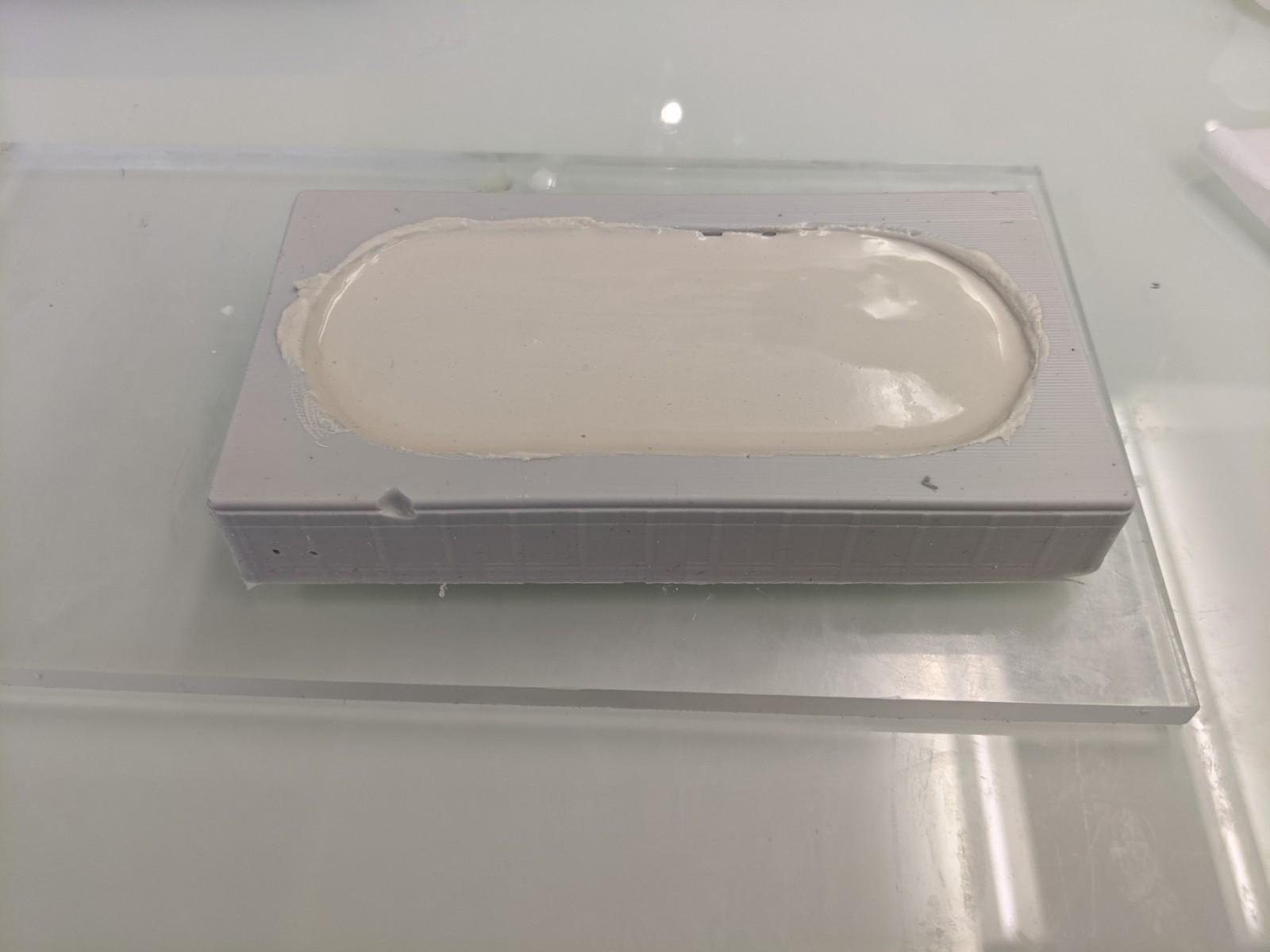
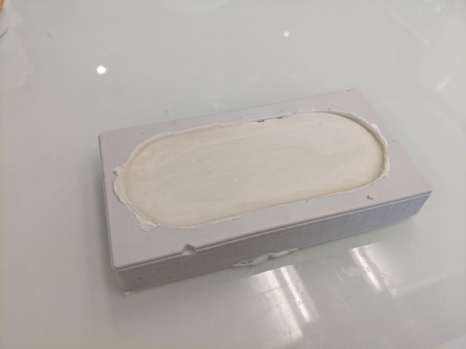
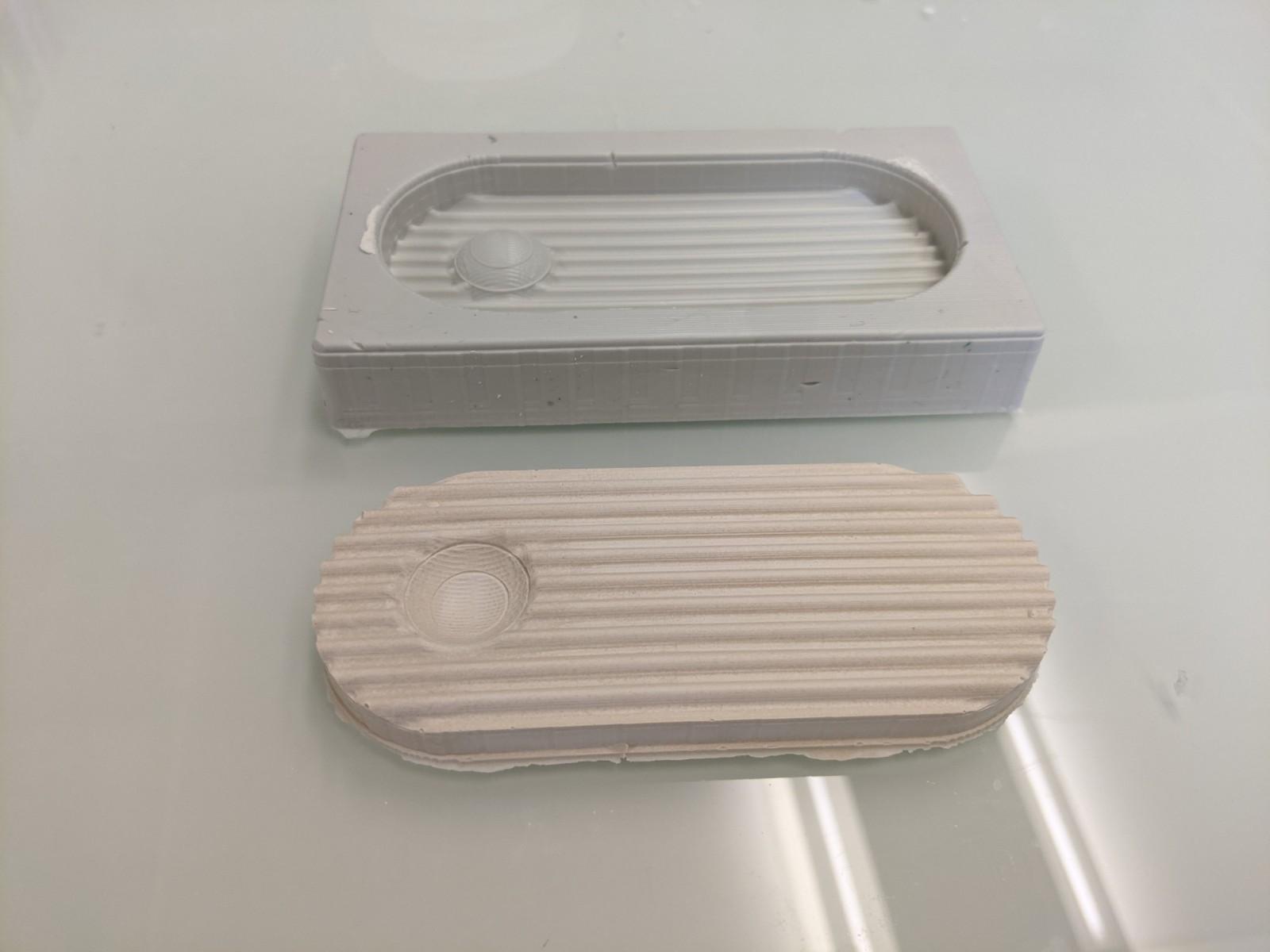
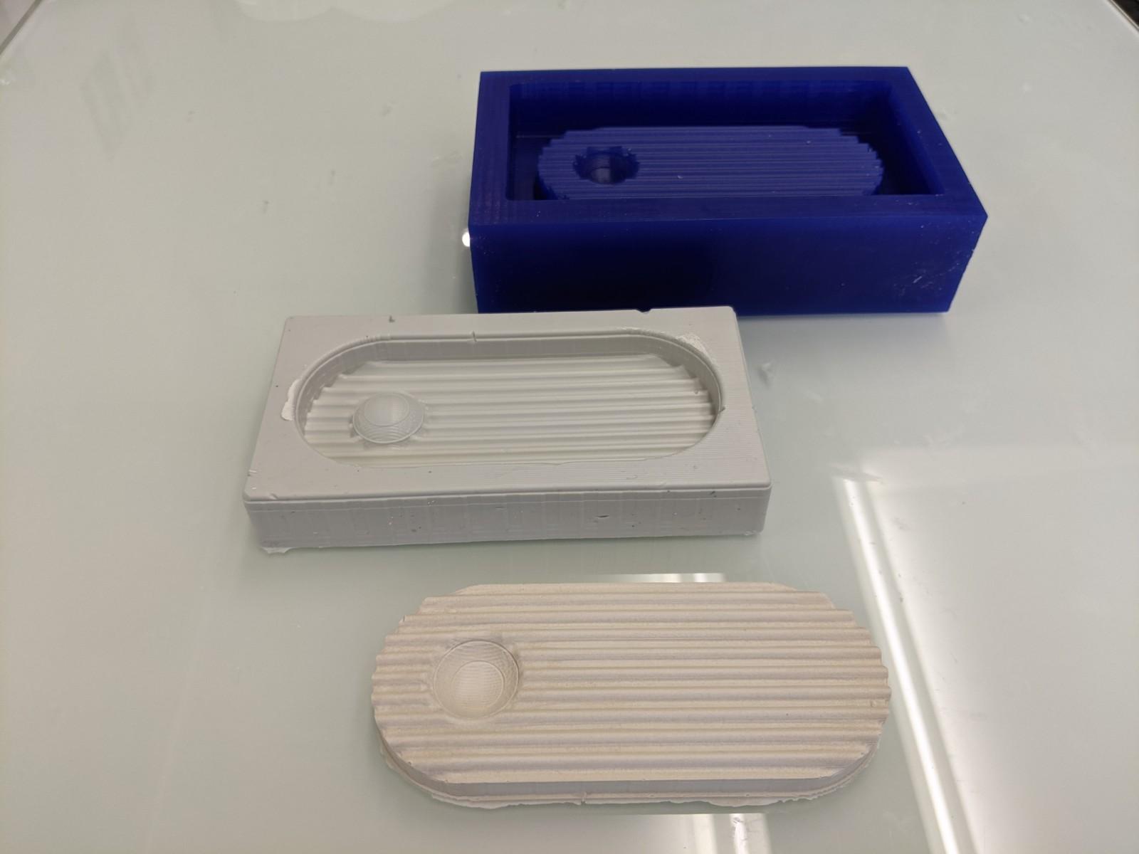
Post processing
Using some sandpaper can really improve the finishing of your objects. I sanded using 80, then 150, then 180 grain/m2 sandpaper, while the parts were not completely dried.
Other plaster experiments
I had an interesting result with some grinded coffee beans. So far the result is rather nice but since I didn't dry them it may develops some bacteria.
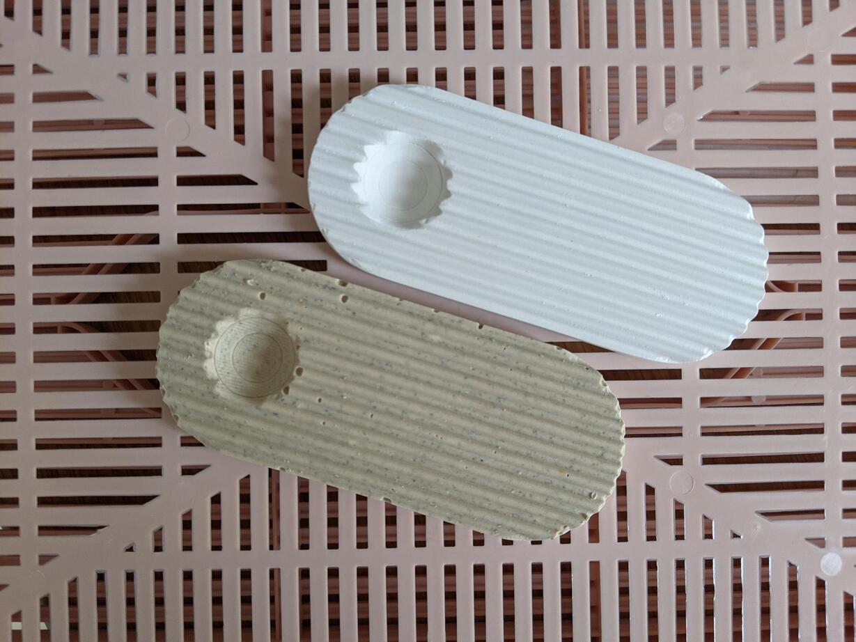
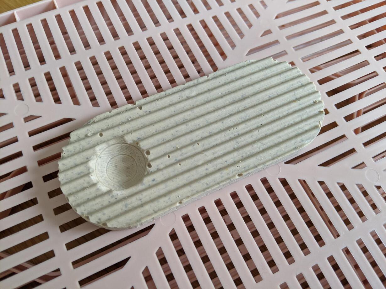
Comparing polyurethane and plaster casting
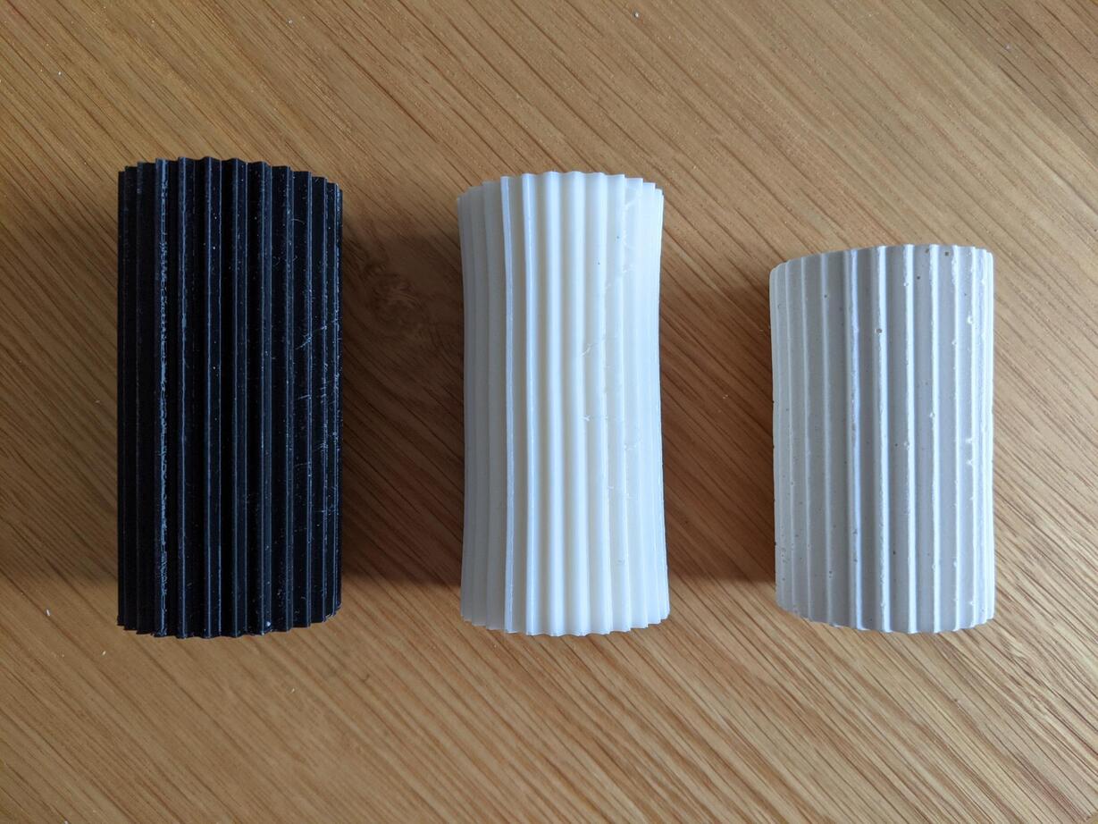
Files
Week 13 - Networking & communications
Week's explorations and achievments
- Group assignment : we achieved a serial communication between two Arduino Uno boards using the SoftwareSerial library
- I tested I2C communication between 3 arduino uno boards: a master board talked to secondary boards thanks to adresses defined in their script and lit up LEDs connected to one of their GPIO
- I implemented the same code on my own boards, as I had 3 functionnal boards providing I2C headers
- I integrated the neopixel protocol in the project to monitor neopixel strips instead of simple LEDs, connected to the secondary boards
- I integrated an RFID reader on my master board which uses the SPI protocol. As done during the week 'Embedded Programming', the RFID reader allows to monitor r,g,b values
- I programmed the I2C communication for the secondary boards to retrieve these r,g,b values from the master board
- I did a bit of soldering to clean my circuit aspect
- I modified my code to demonstrate the behavior I have in my mind for my final project (see video at the end)
Final project demo: only one peripheral adress
For my final project I think of a slightly different process as the usual I2C networking one where all secondary boards have different adresses. Indeed, I intend to use only one peripheral adress for my secondary boards and an I2C bus that will remain open until there is a contact, because I want my elements to be physically independent unless you make them physically interact. It doesn't change so much the code, except it's talking to only one peripheral board.
Also I started going in the direction of my final project in which it's the master role to send the r,g,b values to the secondary boards.
Master's code:
#include <Wire.h>

int t = 0;
int r = 20;
int g = 60;
int b = 30;

void setup() {
  Serial.begin(115200); //speed of the communications
  Wire.begin();
}

void loop()
{

  for (t = 0; t <= 1; t ++) { // 0,1

    Wire.beginTransmission(7);
    if ( t == 1) {
      Wire.write(1);
      Wire.write(r);
      Wire.write(g);
      Wire.write(b);
    } else {
      Wire.write(0);
      Wire.write(0);
      Wire.write(0);
      Wire.write(0);
    }
    Wire.endTransmission();

    delay(100);
  }

}
Secondary's code
#include <Wire.h>
#include <tinyNeoPixel.h>

#define STRIP           1 // PA5 on lightshake
#define NUMPIXELS      15

tinyNeoPixel strip = tinyNeoPixel(NUMPIXELS, STRIP, NEO_GRB + NEO_KHZ800);
int delayval = 300;

int r = 0; int g = 0; int b = 0;
int i = 0; //index of a pixel in the strip
int d1 = 0;

void setup() {
  Serial.begin(115200);
  strip.begin();
  strip.clear();
  Wire.begin(7);     //change address for the nodes, here I use 8 and 9.
  Wire.onReceive(receiveEvent);
}

void loop() {

  if (d1 == 1)
  {
    strip.setPixelColor(i, strip.Color(r, g, b));
    strip.show();
    delay(delayval);
    i = i+1;
  }

}

void receiveEvent(int howMany)
{
  while (Wire.available())
  {
    d1 = Wire.read();
    r = Wire.read();
    g = Wire.read();
    b = Wire.read();
  }
}
RFID reader and SPI protocol
Master board
My master board is the development board based on an ATtiny3216 that I produced during the week Electronic production.
I connected an RFID-RC522 reader to my master board, which communicates together thanks to SPI protocol. It needs a lot more cable than the I2C protocol! You indeed have to connect COPI/MOSI, CIPO/MISO, SCK, SS and RST, as well as 3.3V and GND. I already had tested this RFID reader during the Embedded Programming week, though it was on a commercial board.
Hopefully I had already provided the pins COPI, CIPO and SCK on my ATtiny3216 development board (using the ATtiny3216 pinout, see the week Electronics Production), and I had enough GPIO to connect SS and RST, which are configurable.
My connections between the ATtiny3216 master board and the RFID reader are thus:
- COPI/MOSI together
- CIPO/MISO together
- SCK together
- SS on pin 4
- RST on pin 5
- GND together
- 3.3 V together
In order to use the RFID reader, I used the SPI.h library and the MFRC522.h library.
I also added a single neopixel (a lilypad sewable mini board), that I connected to pin 3 (Data in). I could have used the neopixels that are directly soldered onto my boards, if only they had been correctly soldered! Now that I know how to use solder paste I would probably manage resoldering them correctly, but that was not my priority. Of course, I connected the + to Vcc and the - to ground.
Finally, I am powering the board with USB.
Secondary boards
My secondary boards are two boards made during the week Input Device, based on ATtiny1614. As in the previous example, I connected an LED strip to both of them and powered each of them with 3.7V LipoCell battery. It provides an I2C grove with two 10K pullup resistors.
What it does
This code emulates a gesture that would be important in my final project.
The master board with the RFID reader corresponds to the color palette where you will blend primary colors to obtain a certain tint. Then a secondary board corresponds to an independent light sources that you will dip in the palette to fill the element with the palette's color. Several light sources should be provided.
Technically, the primary colors blending could be achieved thanks to NFC tags, each corresponding to a certain primary color. You can read more about it in my assignment for week 4 - Embedded Programming. I used the same tags. Here are their adress and how i named them:
| Name | Card UID |
|---|---|
| Red | 04 FB 32 22 DA 64 80 |
| Green | 04 F3 30 22 DA 64 80 |
| Blue | 04 87 31 22 DA 64 80 |
| White | 04 96 31 22 DA 64 80 |
| Black | 04 02 34 22 DA 64 81 |
The color blend is made visible thanks to the neopixel rgb led connected to the master board (could be changed for a neopixel ring).
The specificity of this "network" is that the I2C grove connector is by default not connected and I am connecting it only when I want to retrieve the R,G,B value from the master board to the led element
Issues encountered
I had no particular difficulty to integrate the RFID reading part to the master's code. Nevertheless finding the correct timing to retrieve the color in the led element was quite challenging. I wanted it to be able to fill the led element according to the duration of the contact: if you keep the led element on the palette, it will fill pixel by pixel until all are lit up, but it you interrupt the contact, only the first pixels will be lit up.
Also, I wanted to be able to fill the same strip with different colors, if you interrupt the filling, change the palette's color, then fill the remaining pixels.
The sensitive aspect of the code is then when do you increment the index of the pixel currently lighting up. The correct way to do it was in the receiveEvent function in the led element's code:
void receiveEvent(int howMany)
{
    while (Wire.available())
    {
        d1 = Wire.read(); //d1 is
        r = Wire.read();
        g = Wire.read();
        b = Wire.read();
        if (d1==1)
        {
            i = i+1;
        }

    }
}
This is the corresponding I2C transmitting part of the master's code:
      for (t = 0; t <= 1; t ++)
      {

        Wire.beginTransmission(7);

        if (t == 1)
        {
            Wire.write(1);
            Wire.write(r);
            Wire.write(g);
            Wire.write(b);
        }

        else {
        }

        Wire.endTransmission();
        delay(100);

      }
Video
Code
Master's code
Here is all the code of the master's board, including the RFID reading part.
// Clara Devanz
// Fabacademy2023
// Master board with RFID reader (color palette)

#include <Adafruit_NeoPixel.h>
#include <Wire.h> // for I2C communication
#include <MFRC522.h> //RFID reader library
#include <SPI.h> // used for the RFID reader

#define PIX 3 //PIN of the neopixe(s)
#define NUMPIXELS 1 //number of neopixels

Adafruit_NeoPixel pixels(NUMPIXELS, PIX, NEO_GRB + NEO_KHZ800);

int del = 50;  //delay
int t = 0;
int r = 0;
int g = 0;
int b = 0;
int w = 0;
int k = 200;

#define RST_PIN 5          // Configurable
#define SS_1_PIN 4        // Configurable

#define NR_OF_READERS 1

byte ssPins[] = {SS_1_PIN};

MFRC522 mfrc522[NR_OF_READERS];   // Create MFRC522 instance.

/**
 * Initialize.
 */
void setup() {
  pinMode(PIX, OUTPUT);
  Serial.begin(9600); // Initialize serial communications with the PC
  Wire.begin();
  while (!Serial);    // Do nothing if no serial port is opened (added for Arduinos based on ATMEGA32U4)
  SPI.begin();        // Init SPI bus

  for (uint8_t reader = 0; reader < NR_OF_READERS; reader++) {
    mfrc522[reader].PCD_Init(ssPins[reader], RST_PIN); // Init each MFRC522 card
  }
}

/**
 * Main loop.
 */
void loop() {

  for (uint8_t reader = 0; reader < NR_OF_READERS; reader++) {
    // Look for new cards
    // String content[reader];

    if (mfrc522[reader].PICC_IsNewCardPresent() && mfrc522[reader].PICC_ReadCardSerial()) {

      Serial.print(F("Reader "));
      Serial.print(reader);
      // Show some details of the PICC (that is: the tag/card)
      Serial.print(F(": Card UID:"));
      Serial.println();

      readTags(mfrc522[reader].uid.uidByte, mfrc522[reader].uid.size);

    }

      // Halt PICC
      mfrc522[reader].PICC_HaltA();
      // Stop encryption on PCD
      mfrc522[reader].PCD_StopCrypto1();

  } //end of the loop with the readers

      for (t = 0; t <= 1; t ++) { // 0,1
      Wire.beginTransmission(7);

      if (t == 1){
      Wire.write(1);
      Wire.write(r);
      Wire.write(g);
      Wire.write(b);

      }

      else {
      //Wire.write(0);
      //Wire.write(0);
      //Wire.write(0);
       //Wire.write(0);
      }

      Wire.endTransmission();
      delay(100);
      }

}

/**
 * Helper routine to dump a byte array as hex values to Serial.
 */
void readTags(byte *buffer, byte bufferSize) {

  String adress="";

  for (byte i = 0; i < bufferSize; i++) {
    Serial.print(buffer[i] < 0x10 ? " 0" : " ");
    Serial.print(buffer[i], HEX);
    adress.concat(String(buffer[i] < 0x10 ? " 0" : " "));
    adress.concat(String(buffer[i], HEX));

  }

  adress.toUpperCase();

  if (adress.substring(1) == "04 FB 32 22 DA 64 80")
  {
    r += 10;
    Serial.print(F(" red tag identified")); // String wrapper for printing strings in the serial monitor and using Flash memory instead of SRAM
    pixels.setPixelColor(0, pixels.Color(r,g,b)); //starts at 0!
    pixels.setBrightness(k);
    pixels.show();
    Serial.println();
    Serial.println("Value of red color is " + String(r));
    delay(del);
  }

  else if (adress.substring(1) == "04 F3 30 22 DA 64 80")
  {
    g += 10;
    Serial.print(F(" green tag identified"));
    delay(del);
    Serial.println();
    pixels.setPixelColor(0, pixels.Color(r,g,b)); //starts at 0!
    pixels.setBrightness(k);
    pixels.show();
    Serial.println();
    Serial.println("Value of green color is " + String(g));
    delay(del);

  }


  else if (adress.substring(1) == "04 87 31 22 DA 64 80")
  {
    b += 10;
    Serial.print(F(" blue tag identified"));
    delay(del);
    Serial.println();
    pixels.setPixelColor(0, pixels.Color(r,g,b)); //starts at 0!
    pixels.setBrightness(k);
    pixels.show();
    Serial.println();
    Serial.println("Value of blue color is " + String(b));

  }

  else if (adress.substring(1) == "04 96 31 22 DA 64 80")
  {
    Serial.print(F(" white tag identified"));
    delay(del);
    Serial.println();
    r=0;
    g=0;
    b=0;
    k = 200;
    pixels.setPixelColor(0, pixels.Color(r,g,b)); //starts at 0!
    pixels.setBrightness(k);
    pixels.show();

  }

  else if (adress.substring(1) == "04 02 34 22 DA 64 81")
  {
    Serial.print(F(" black tag identified"));
    k -= 20;
    Serial.println();
    Serial.println("Value of brightness is " + String(k));
    delay(del);
    Serial.println();
    pixels.setBrightness(k);
    pixels.setPixelColor(0, pixels.Color(r,g,b)); //starts at 0!
    pixels.show();
  }

  else
  {
    Serial.print("unknown tag");
    delay(500);
  }

}
Secondary's code
Here is all the code of the led element's board
//Clara Devanz, inspired by the code by Luis Diaz cited by Adriano Torres
//Fab Academy 2023
//ATtiny1614 secondary board (led element)

#include <Wire.h>
#include <tinyNeoPixel.h>

#define STRIP           1 // PA5 on lightshake
#define NUMPIXELS      15

tinyNeoPixel strip = tinyNeoPixel(NUMPIXELS, STRIP, NEO_GRB + NEO_KHZ800);
int delayval = 100;

int r = 0; int g = 0; int b = 0;
int i = -1; //index of a pixel in the strip
int d1 = 0;

void setup() {
  Serial.begin(115200);
  strip.begin();
  strip.clear();
  Wire.begin(7);     //change address for the nodes
  Wire.onReceive(receiveEvent);
}

void loop() {

  if (d1 == 1)
  {
    if (i >= NUMPIXELS) {i=-1;}
    strip.setPixelColor(i, strip.Color(r, g, b));
    strip.show();
    delay(delayval);
  }

  else {
    delay(delayval);
  }

}

void receiveEvent(int howMany)
{
  while (Wire.available())
  {
    d1 = Wire.read();
    r = Wire.read();
    g = Wire.read();
    b = Wire.read();

    if (d1==1)
      {i = i+1;}
  }

}
Files
Week 16 - Applications and implications
Here are the key questions we were asked to answer about our final project on week 16.
What will it do?
My project will consist in a set of tools to experiment light art.
Users will interact with it thanks to the following gesture:
- Setting a RGB color in one of the palette pod, thanks to primary colors pucks.
- Attribute this color to a led element by placing it on the palette pod. The longer the led element is in contact with the palette pod, the more the led element gets lit up.
- the led element can be filled with different colors if it's placed on another pod or if the user changes the color of the pod
- Mix the colors of the led element if it has been filled with different colors, by shaking the led element
- Place led elements on the scene
- Place other passive elements of the kit on the scene
- Enjoy the light effects, experiment various configurations
Who has done what beforehand?
Light art has been explored in many ways by artists and crafters. Among the more famous is the minimalist artist Dan Flavin who worked with neon tubes.
The led elements that I want to provide resemble to light tubes used in photography or filming. Similar coloured lights can also be found in interior design.
I will try building the more possible by myself, though I know I will use Neopixel RGB led strips instead of building the led strips myself.
What will you design?
I will probably be too short on time to design all the elements I would ideally like to provide in my set of tools. Here's the elements I would like to design in order of priority:
- the led element, including the design of:
- PCB and wiring
- Clear / diffusing case (maybe molded silicone)
- Foot, allowing the tube to stand and hiding all the electronics. The bottom of the foot will expose contact pads to temporarily connect the foot element to the color palette
- the color palette, including the design of:
- PCB and wiring for each pods
- Overall palette casing
- the primary colors pucks, including the design of:
- PCB (optionnal, only if leds are included in the puck)
- Puck casing
- 3D framed scene
- ribbed obstacles, in particular the design of molds.
- a piece of furniture or casing that contains all the elements of the set of tools
- screens
- windows
What materials and components will be used?
Led elements
Here's the material needed for one led element:
- Neopixel RGB led strips (WS218) with sufficient density (60 leds per meter). I need at least a meter to have several elements (an element should not exceed 15 leds).
- ATtiny1614
- MMA8458 3-axis accelerometer
- Li-Po battery 3.7V
- Small electronic components: capacitors (to filter signals), resistor (to protect the strip), switch (to turn the device on/off), headers (for UPDI/FTDI)
- Wires, tin
- PCB copper plate
- Copper tape for the contact pads?
- matt PLA/ABS for the foot
- Option 1: silicone for the diffusing case. Option 2: diffusing acrylic (not coloured)
- ? matt PLA/ABS to provide rigidity to the tube ?
- a UPDI/FTDI programmer board
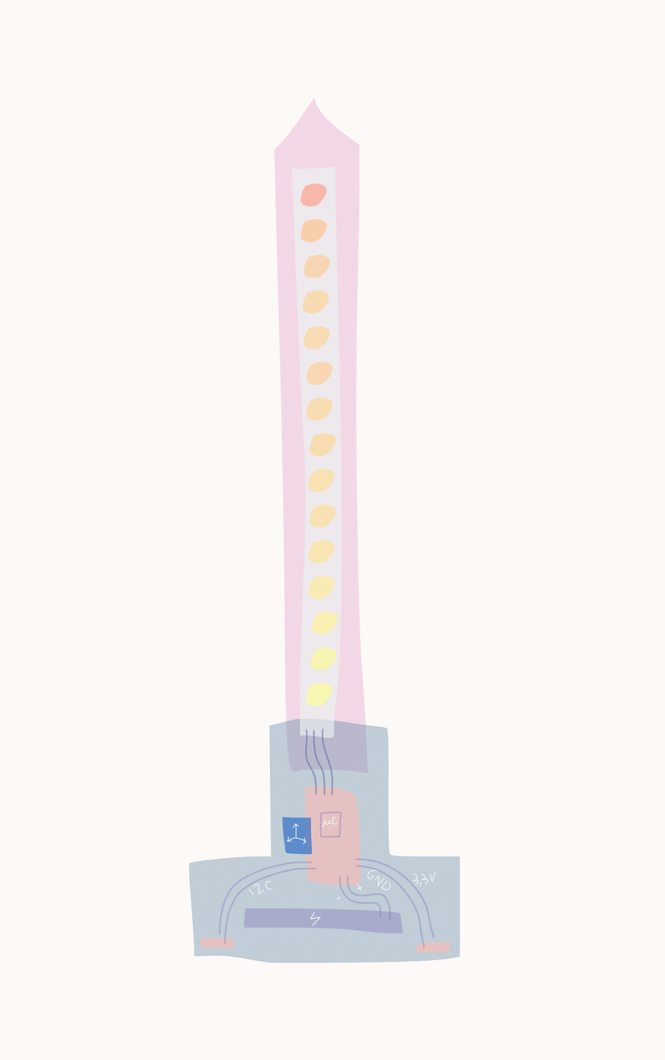
Color palette
Here's the material needed for one pod (ideally 3 pods would be provided)
- ATtiny3216
- RC522 RFID reader
- Neopixel ring
- USB sector power supply / optionally USB power bank
- Small electronic components: capacitors (to filter signals), resistors (to protect the neopixel ring + I2C pullup resistors), switch (to turn the device on/off), headers (for testing and for UPDI/FTDI)
- Wires, tin
- PCB copper plate
- Copper tape for the contact pads?
- Plywood for the casing
- Diffusing acrylic or other diffusing texture (felt, paper, wood veneer)
- a UPDI/FTDI programmer board
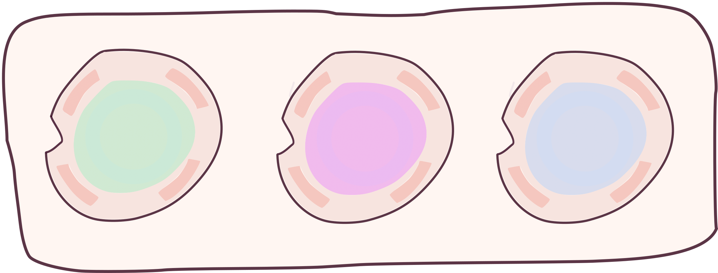
Primary colors pucks
Here's the material needed for one puck (5 pucks would be provided, minimum 3 pucks for R, G and B)
- RFID passive tag sticker
- 3mm thick plywood
If the puck is lit up:
- simple led(s)
- cell battery
- resistor
- wires, tin
- wood veneer
Ribbed obstacles
Here's the material needed for a ribbed obstacle
- PLA / wax to create a premold
- silicone to create a mold
- Plaster / Drystone / Wax for casting
- Epoxy resin for casting ?
- Other casting materials ?
- Or ABS sheet for vacuum forming ?
- Paper
3D framed scene
Here's the material needed for the scene
- Plywood
- Depending on the assembly system: nothing if press-fit, or glue/ screws/ magnets
- Optionnaly if there's a false floor to hide led elements inside : diffusing acrylic
The 3D framed scene could also be fully integrated in the overall piece of furniture.
A piece of furniture
I am really not sure about the final shape of this furniture or casing. Will it be a standing furniture, will it hang on a wall, or be laid on a table? Also it may just be a simple suitcase. Anyway I will probably need:
- wood
- drawer metal slides / piano hinge / magnets...
- screws
Screens
A screen could be made of:
- Wood frames
- MDF slats
- Paper / Felt
Windows
A window could be made of:
- Plywood
Where will they come from?
We already have a lot of material in the Fablab, coming from our usual suppliers (Farnell / Mouser for electronics, trotec for plywood and acrylic, ). Some should be purchased in craft / art material (paper, felt, drystone or plaster)
How much will they cost?
Here's a (non extensive) Bill of Material
| Component / Material | Price per unit (€) | Quantity | Information |
|---|---|---|---|
| 1M/60leds WS2812 Digital RGB LED Flexi Strip | 16,80 | 1 | |
| Neopixel ring 16 or 12 RGB LEDS | 7,50 | 3 | |
| MMA8458 3-axis accelerometer | 7 | 4 | |
| RC522 RFID readers | 4 | 3 | |
| NFC tag stickers | 1 | 5 | |
| ATtiny3216 | 1,3 | 1 | |
| ATtiny1614 | 1 | 4 | |
| LiPo 3.7V battery | 10 | 4 | |
| Plywood board 300*600 3mm thick | 4,58 | 4 | |
| Plywood board 600*1200 12mm thick | 50 | 1 | |
| Silicone RTV Esprit composite 1kg | 43,65 | 1 | |
| Drystone / Plaster 1kg | 12,95 | 1 | |
| LED diffusing acrylic trotec 300*600mm, 3mm thick | 13,21 | 1 | |
| Matt PLA FormFutura 750g spool | 34,99 | 1 |
What processes will be used?
- Electronics design, PCB milling, hand soldering
- Laser cutting
- 3D printing
- Molding and casting
- Large format machining ?
What questions need to be answered?
- How to provide a nice finishing for the contact pads parts?
- How to charge easily the batteries?
- How is the scene integrated in its environment? (in order to define the 3D frame and the piece of furniture)
How will it be evaluated?
The project will be evaluated by test users. The main features to evaluate is:
- Do the gestures to change the light colors feel intuitive?
- Does the set of tools allow interesting expressivity?
- Does it feel inviting for more experiments?
What has been done for now?
Here's what have been done:
- Three models of ribbed obstacles
- Two successful molds for ribbed obstacle
- Ribbed obstacles casted in polyurethane and plaster
- Master board design (for the color pallette pod)
- Code for the color pallette color change when a NFC tag is detected
- Code to send a color value in I2C to a secondary board
- Code to light the neopixel strip of the secondary board according to the duration of the contact
- Code to mix two colors if a shaking movement is detected
What's next?
The first priority is working on the contact pad design of the led element and the color palette.
Week 17
This week I worked only on the candle light element.
- I tested my PCB casing modelled with Fusion 360 and printed in PLA on Raise 3D Pro 2 machines. I adjusted my designs to obtain a case in two parts, top and bottom. The bottom part contains the PCB and battery. A first hole allow me to place a switch to turn the circuit on and off. A second hole will be used for the contact pads that will connect this circuit to the palette circuit.
- I did the casing for the neopixel strip, also using Fusion 360. I printed the tube case and lasercut a board of Troglass LED acrylic to diffuse the light.
- I redesigned the PCB in Kicad, to have something more compact and with vertical headers. The design is overall very close to the lightshake one, designed and produced during the week Input device (version for an MMA8458 accelerometer breakout board)
- I milled the PCB
- I hand soldered the components. To reduce the volume of the circuit, I had to cut and bend the header pins of the accelerometer breakout board and of my board's pins, then soldered them together.
- I secured everything in the casing and tested: everything works fine!