Week 15 - Wildcard week: generative design and waterjet machining
Goals
- Generate an svg pattern with code, using at least one random parameter
- Machine this pattern using a waterjet cutting machine
Week's explorations and achievements
- I tested the engraving job quality with the waterjet cutting machine
- I tested aluminium inlays in a stoneware hole, also thanks to the waterjet machine
- I explored p5.js to make various patterns based on the principle of Truchet tiles
- I found a method to work with vector graphics in p5.js and export svg files
- Unfortunately we were very low on the abrasive sand stock so I couldn't really explore the waterjet machining of my patterns.
Waterjet cutting
Machine presentation and best practices
The model we have at the Fablab is a ProtoMAX compact waterjet cutting machine, from the company OMAX. It allows us to cut a wide variety of materials thanks to a very high pressure water jet and a particular abrasive sand made mainly with grenat stone.
- Pressure: 2000 bar
- Table XY dimensions: 369 mm x 393 mm.
- X-Y maximum movement: 304 x 304mm
- Max thickness: 25mm (depending on the material)
Once correctly installed, the machine doesn't require particular safety measures to protect the person operating it since it's all closed. Nevertheless be sure to handle the abrasive sand with care, it could itch your skin: it's always best to wear disposable latex gloves and a respiratory mask.
Also some best practices must be kept in mind to avoid damaging the machine or extend its lifetime:
- Keep the cover open when you're not using it, to keep the moist at a reasonable level
- Unplug the junction tube of abrasive once you're done machining, to avoid moist in the abrasive container. Of course don't forget to plug it again when you'll use the machine again.
- Make sure the water evacuation in your lab is always correct
- Rinse the abrasive deposits regularly
- Empty the water one in a while
- Always make sure the water tank is filled when you're launching a job
- Always home the machine when you turn it on (clicking on the red message boxes in Omake)
- Always start with a test before cutting anything, by placing the head between two slats and let a test running for 30 seconds ('Test' button in the OMake software)
- Be very careful to anticipate the clamps position when you're setting a path: you want to avoid at all cost that the waterjet head hits the clamps
Preparing the path in the Layout software
Once you have your design file ready in a .dxf format, you can prepare the job in the Omax software called Layout
A sensitive situation I often faced with the Layout software is the dimensions of my job, which are not respected when I import a .dxf. It may be a problem with my version of Inkscape when I save the file as a .dxf. A strange way I found to solve this is to reopen the dxf file in Inkscape (selecting manual scaling of 1.00), and resave it as a .dxf. Also, tick the 'respect dimensions' in the dialog that opens when you're importing the dxf from layout.
After having check that the dimensions are consistent, move the design correctly on the grid (near the origin seems more logical to me). Don't hesitate to click on Clean design (button in the right menu) to avoid any path problem.
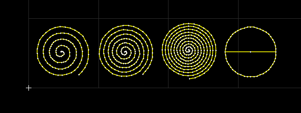
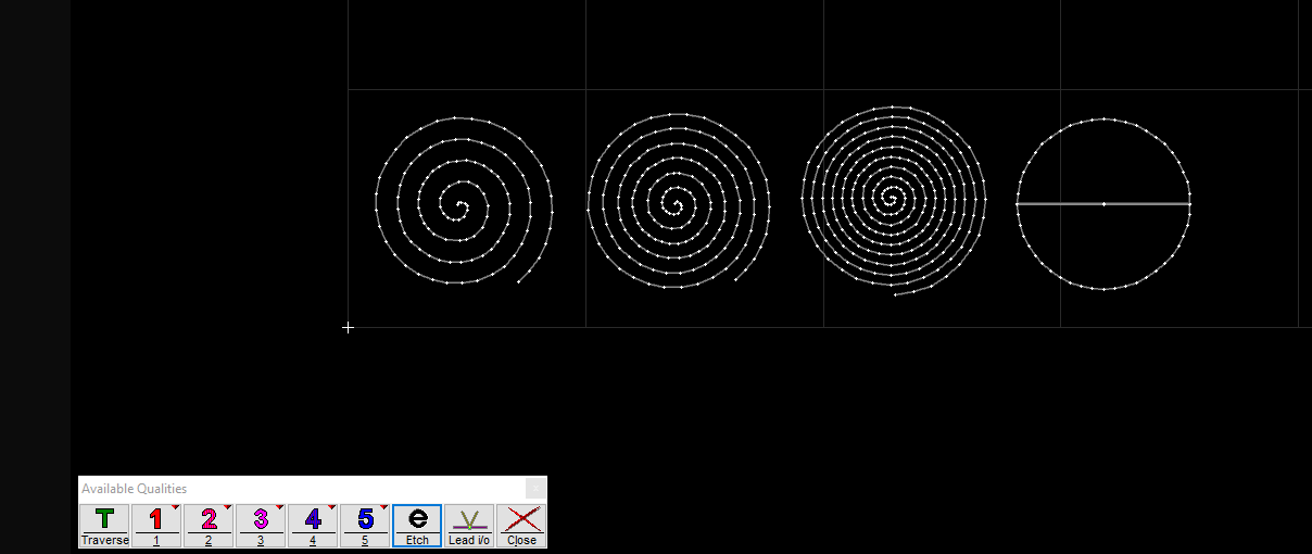
Then choose the cutting quality for your different design paths. Here I wanted to engraved everything, so I chose the quality e (black).
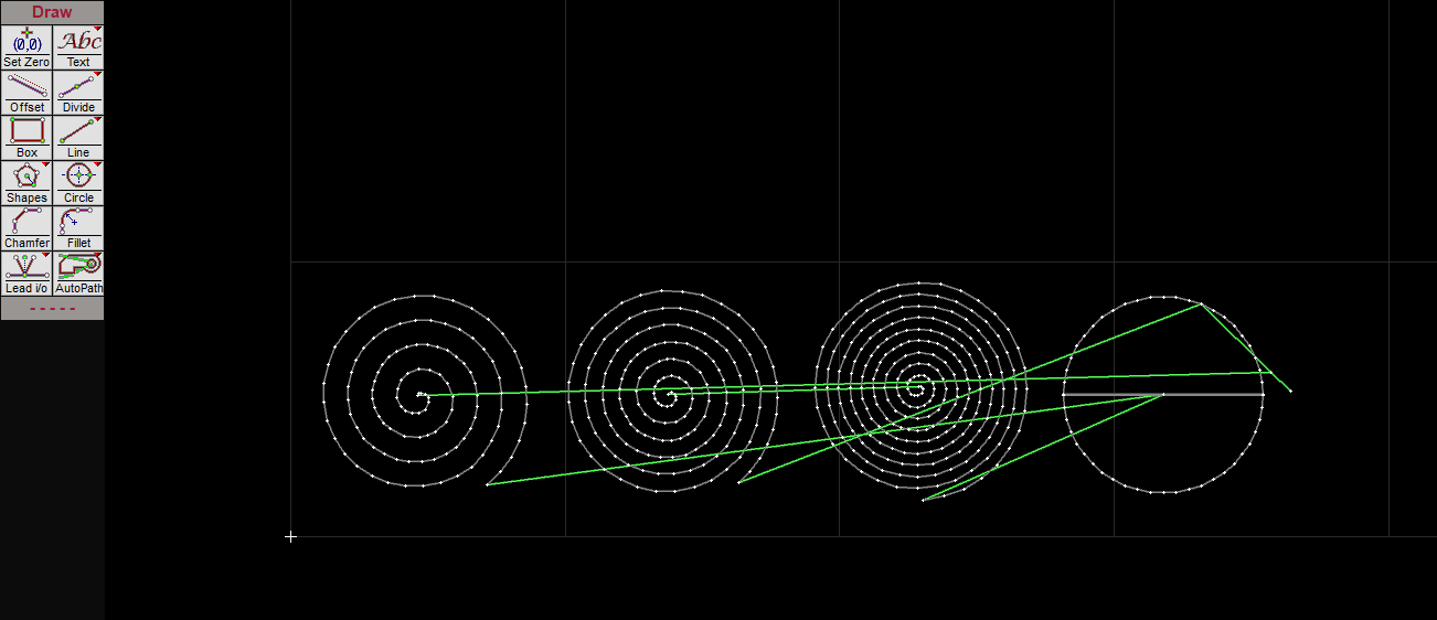
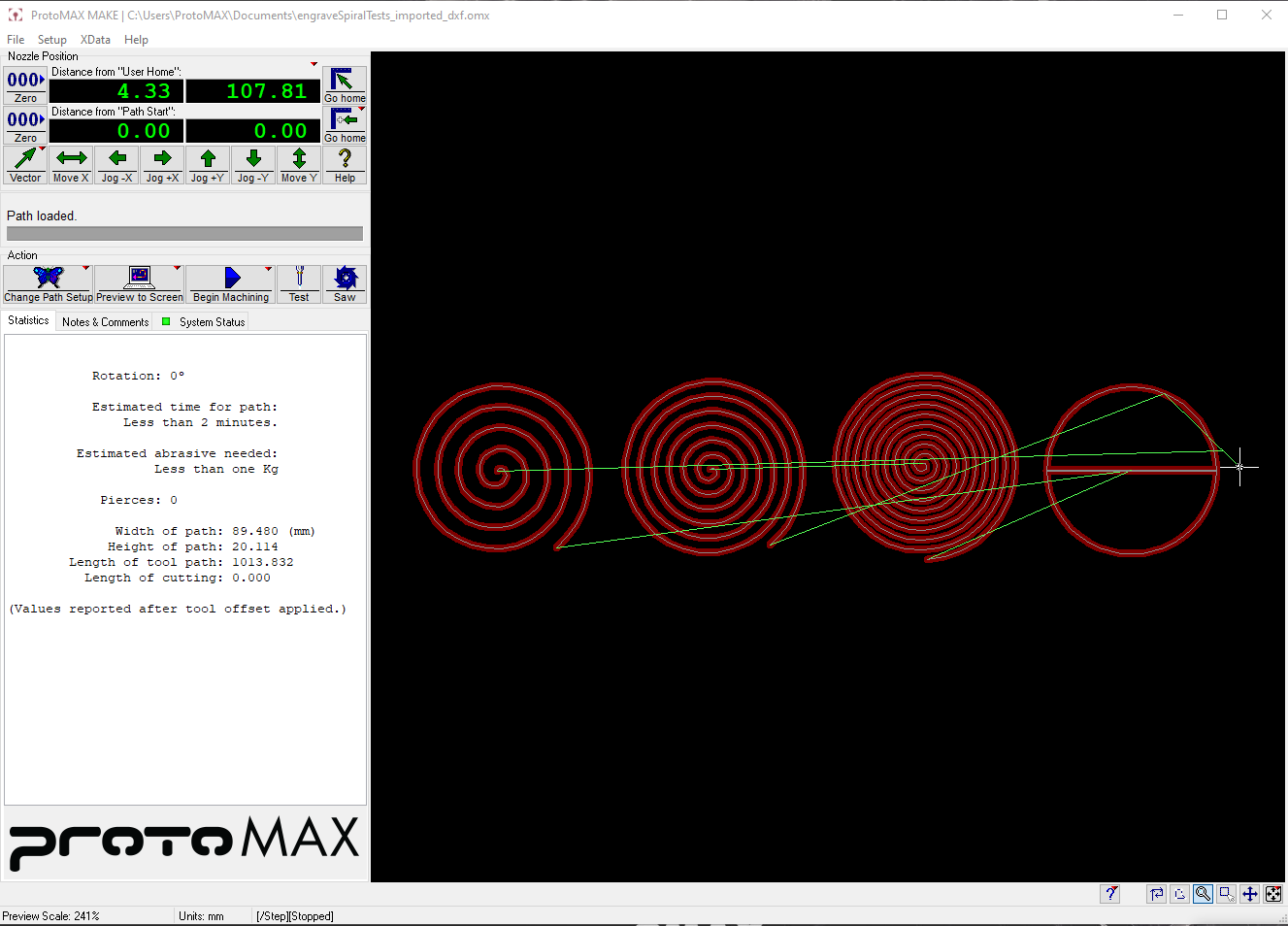
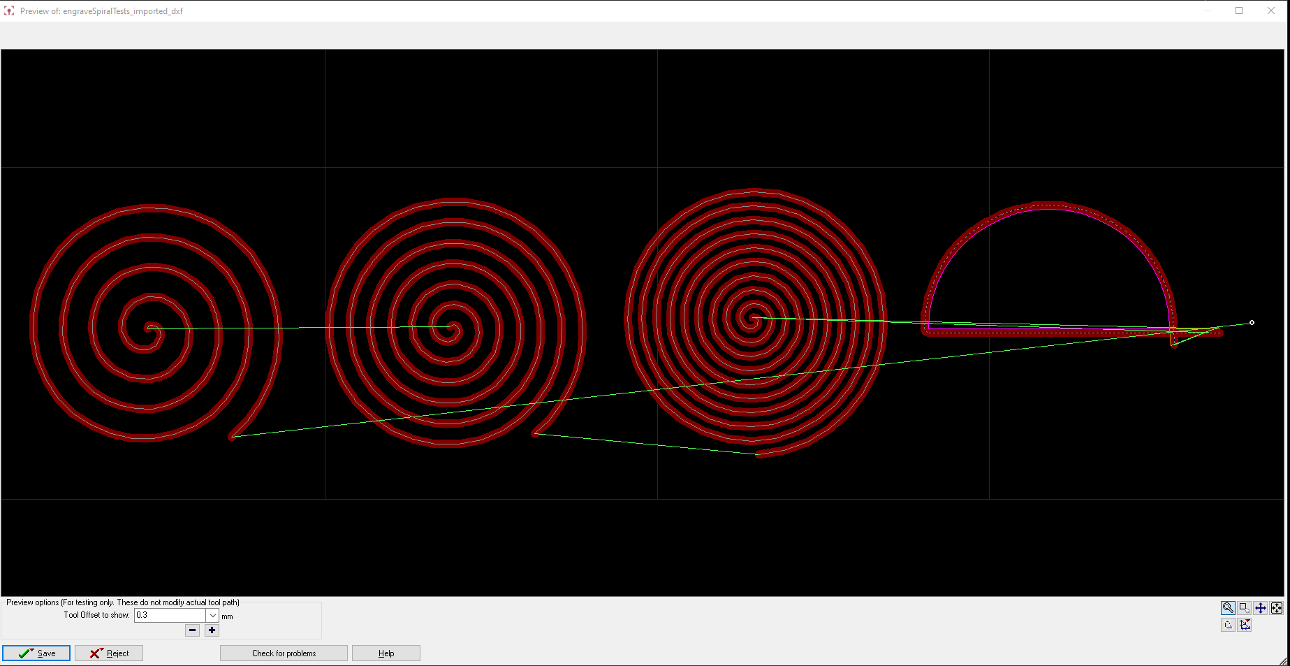
Then click on the Autopath button in the left menu. The softwares calculate automatically the head's path. The green lines are movements made without cutting, and the brown lines corresponds to the moment when the waterjet progressively go through the material. (On this screenshot you don't see any brown line because it's an engraving job and not cutting).
Click on POST in the right menu and choose the starting point of your job, by clicking on it. It must corresponds to an end point of a line. If it doesn't the software doesn't allow you to continue. Here the starting point is the right end-line point.
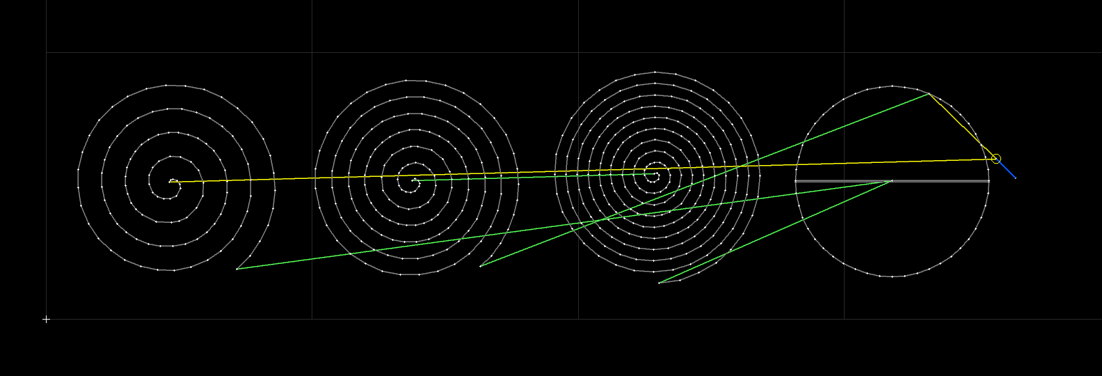
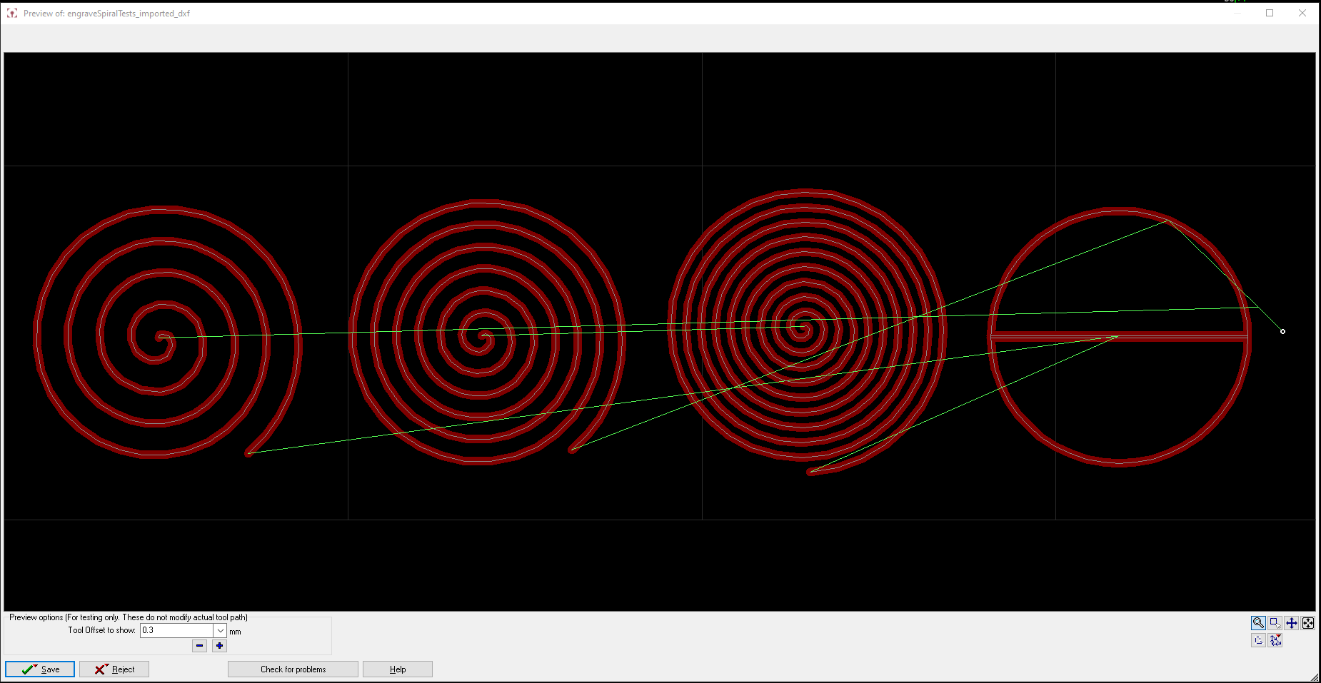
Click on the path and it will open the job's preview. The dark red thick line corresponds to the kerf of the waterjet. In an engraving job it is positionned on the middle of the line. For cutting jobs it depends if the software detects the shape as an internal cut or an external cut (see below the inlay section).
Launching a job on the machine and with Omake software
-
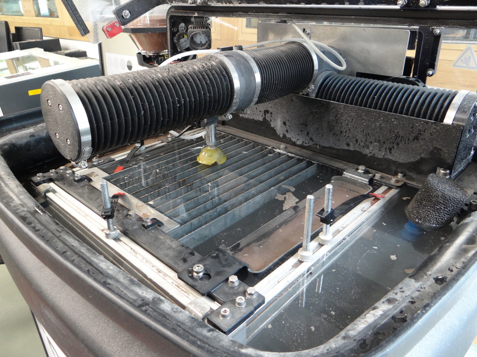
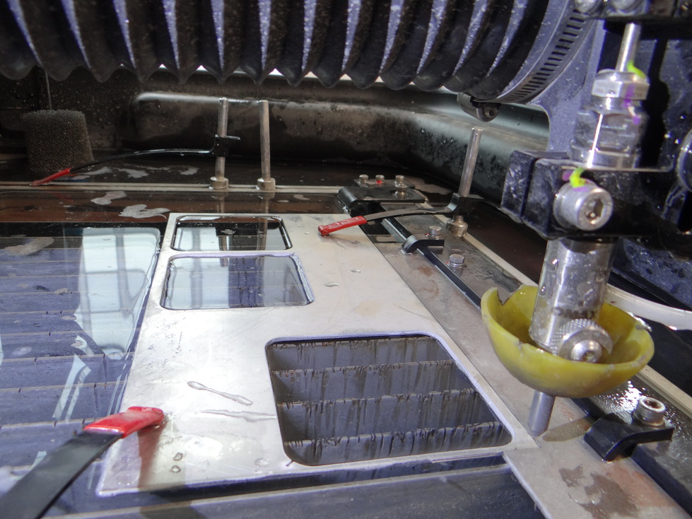
Fill the water tank at the desired level (usually near the surface of your material). Make sure the evacuation tube is positionned high enough for the water not to flow without reaching the desired level. The grey foam filter must be placed on the top og the evacutation tube as in the picture. To fill the tank we use the shower head coming with the machine.
-
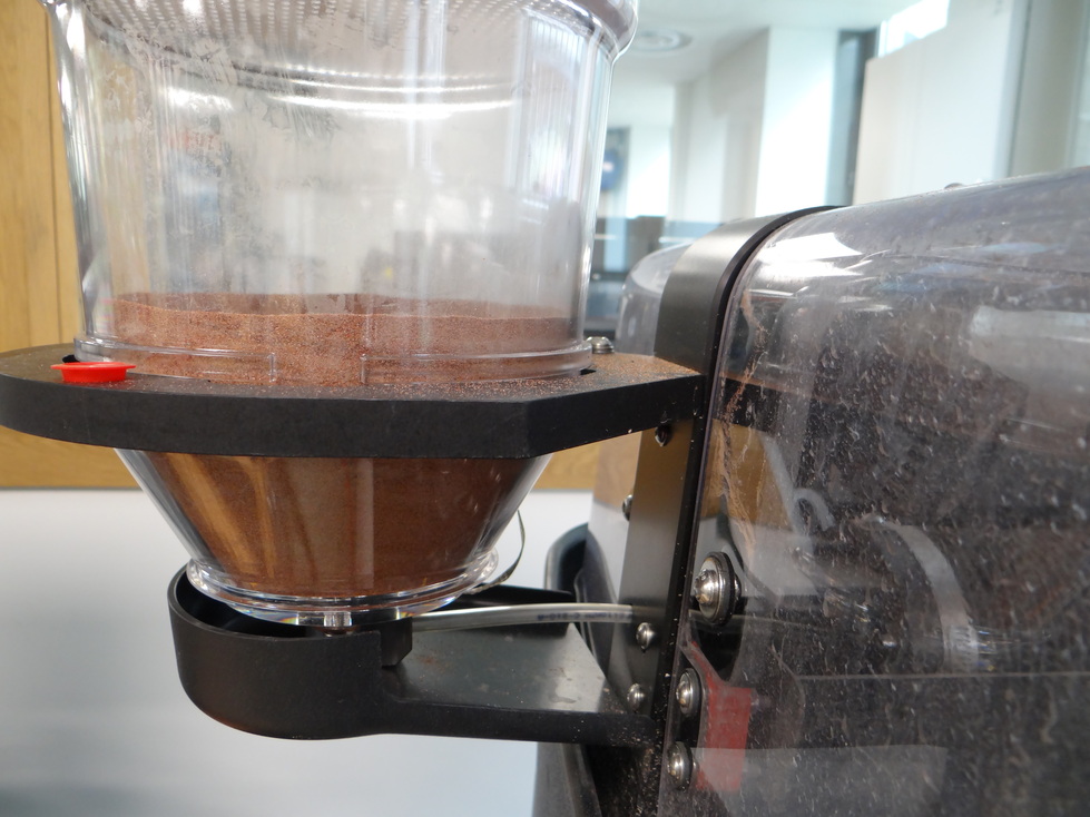
Check that you have enough abrasive sand and connect the plastic transparent tube going from the machine to the abrasive reservoir. There's a small hole in the bottom of the reservoir [spoiler : I did not have much abrasive sand, you'll see the consequences on later pictures]
-
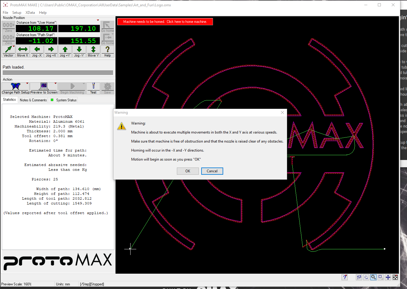
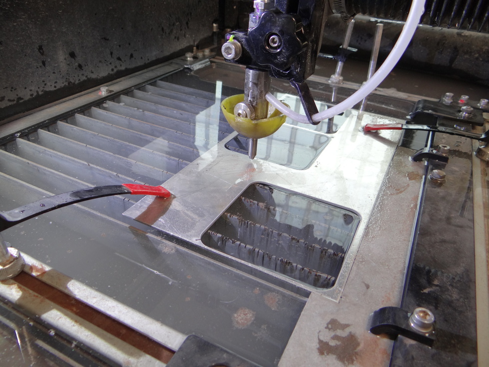
Turn on the machine. Open the software Omake. It will display warnings saying you need to home the machine's head. Check that there's no obstacles such as clamps in the way, then click on this message to home the machine (to the absolute x,y).
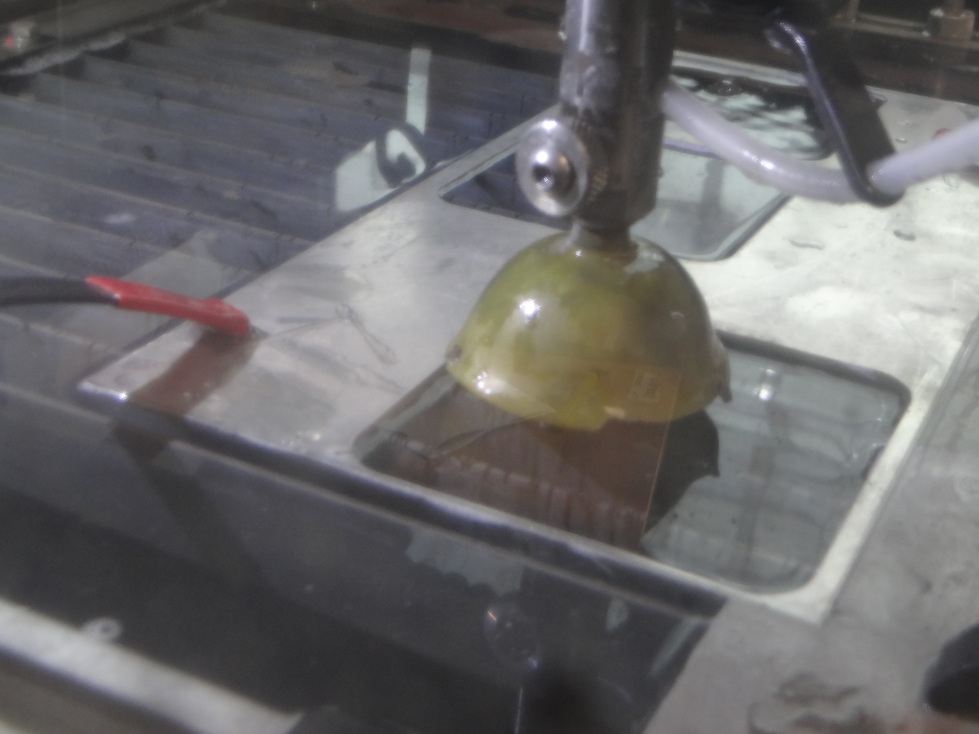
The head should be in the following position.
-
Place the head between two slits (using the green arrows in OMake), not above any material . Turn the yellow cap downside and close the cover . Do a 30 seconds test by clicking on the red 'Test' button in Omake. Select the first toggle button then launch the test and let it run for 30 seconds. You should see abrasive sand running in the tube to the machine. Interrupt the test by clicking on stop.
-
Place your material if it's not already done, secure it with the clamps. Then do the Z: it's manual on this machine, you should simply lift the yellow cap and loose the big black screw to be able to move the head. As advised by the company during the training, I wet the Z-position approximatively 2-3 mm above the top surface of my material. We use an aluminium piece with a 2-3 mm thickness to do so.
-
Set the relative x and y zero. Caution! The origin is the path start you set in Layout so it could be in really various places compared to your design. Here I homed it on the right side of my path. Click on the 000 button on the second line... NOT the 000 button of the first line, which is reserved for absolute X and Y. You don't want to change this one.
-
Put back the yellow cap, close the machine, and you're ready to go!
-
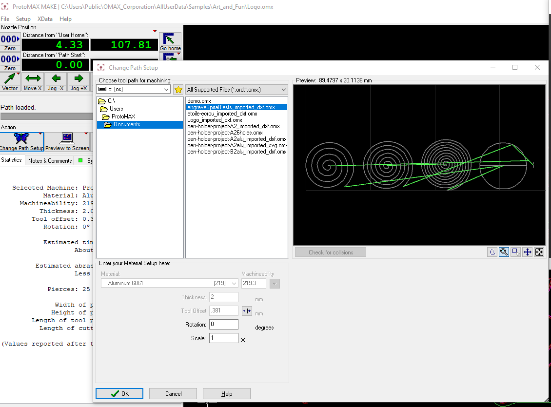
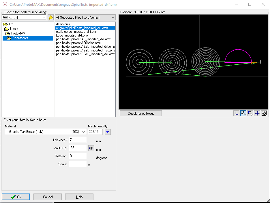
In OMake, click on the button 'Change path setup', then navigate in the files to find the layout file saved from the previous step. Check that it's the correct file. Set the correct material (material type and thickness). If you only engrave you don't have to indiquate the material thickness. Double check the dimensions, the starting of the path, that the clamps don't go in the way, that you enough abrasive sand, that the yellow cap is down...
And click on start! You can pause the job anytime if you have any doubt.
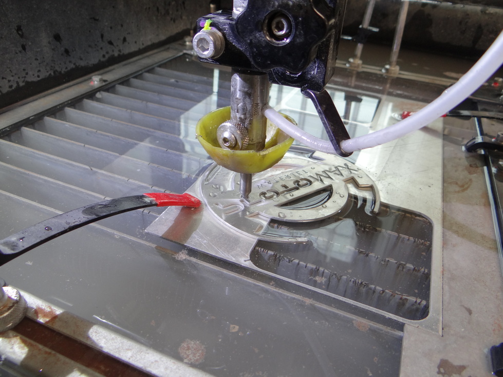
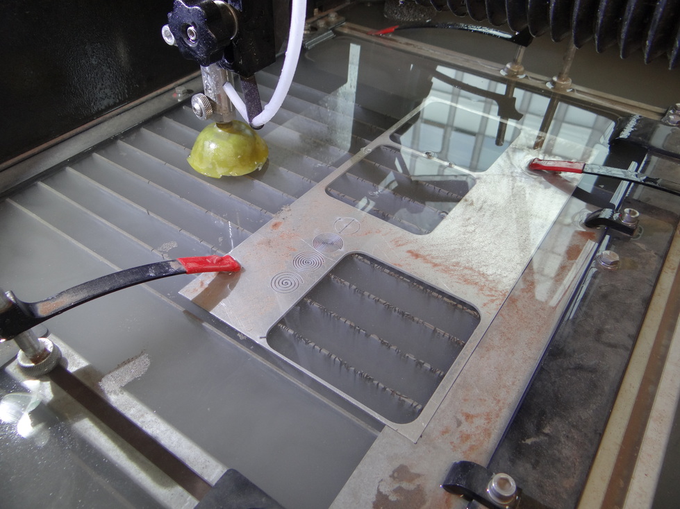
Here's a picture after an engraving test on aluminium:
Waterjet explorations
I wanted to try two things:
- engraving
- inlays of a material inside another one
Engraving
My first attempt with engraving was prepared directly in the Layout software, by selecting the cutting quality 'e' (black), for engrave. It doesn't work the same way as engraving in jobcontrol on a lasercutter: here all shapes are converted to paths with no fill. It's then closer to the marking operation in job control, which follows a path but doesn't go all the way through, than the raster engraving operation in JobControl where the head runs from one side of the x-axis to the other.
To do a similar raster engraving I believe that you have to use another Omax software such as IntelliEtch.
Engraving aluminium
It worked just fine.
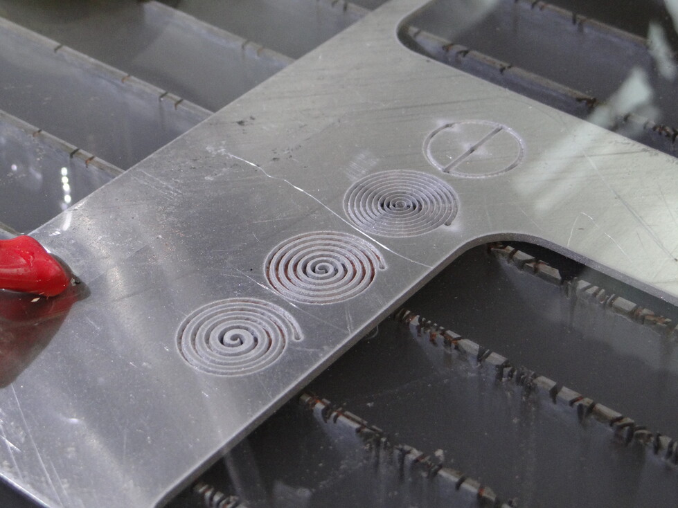
It goes all the way trough in some spots.
Engraving stoneware
Not sure of the correct name in english, in French it would be grès porcelainé (description in French here). I indeed found these tiles used for interior decoration on a second hand online shop (leboncoin).
I changed the half circle path for a cutting job (quality 3) in Layout. I used the settings of Granite Town Brown (Italy) material in OMake with a thickness of 7mm (for the cutting operation I added).
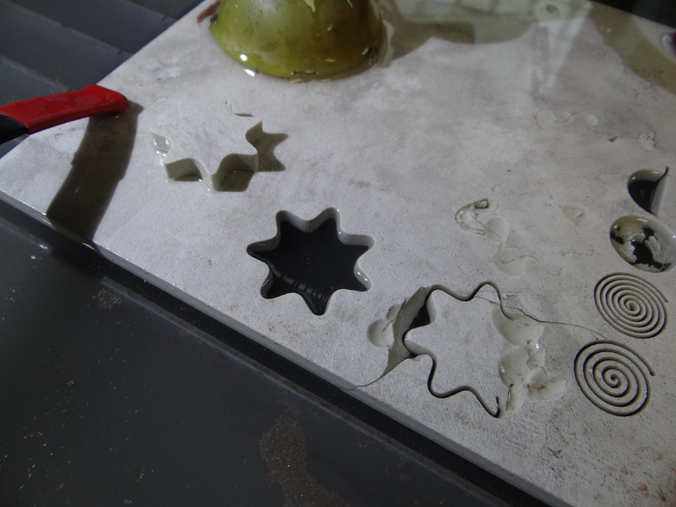
Here's the result:
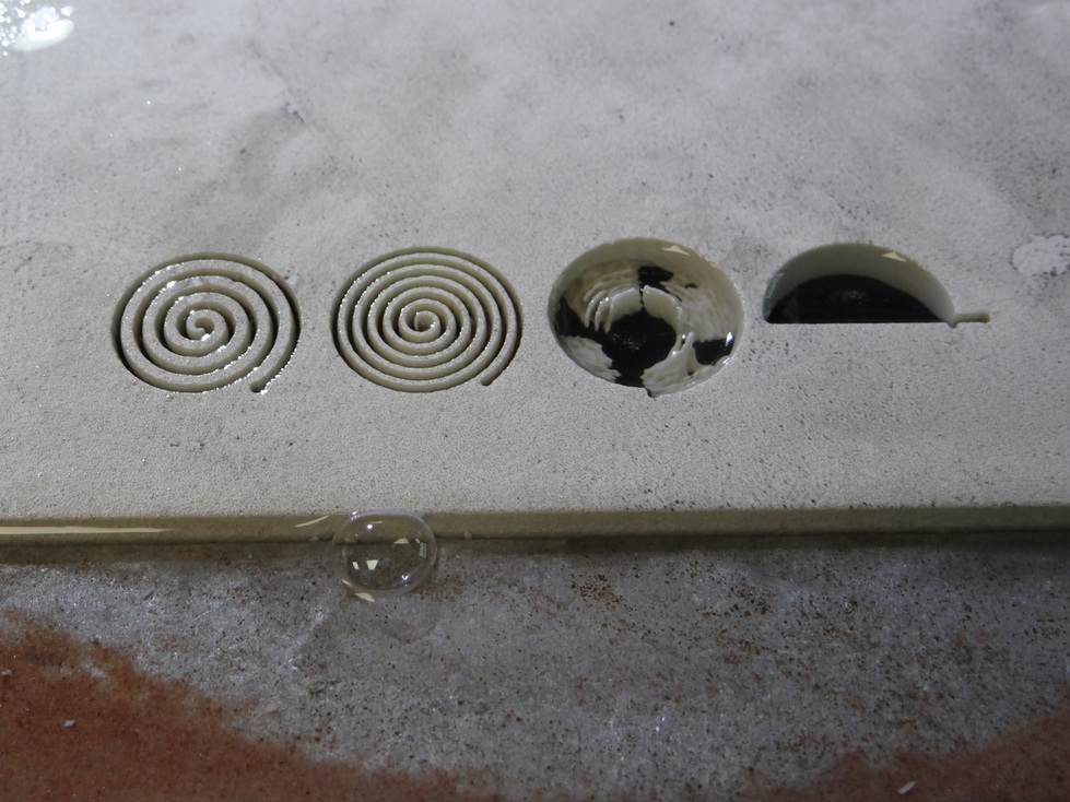
The last engraving broke the surface but the two others are really clean. The cut is clean too.
Inlays
I wanted to try inserting a metal inlay in a stoneware hole. The only real difficulty is to correctly configure your path in order to have a waterjet cut on the correct side of the path you designed. Unfortunately I'm not really sure if there's a straightforward to indicate way to the layout software, it wasn't clear during the training if there were such a functionnality in Layout. So here's the principle I took advantage of to use the autopath function the way I wanted.
The logic of Layout is that if you have a shape inside another one, it will be interpreted as an internal cut, and will thus cut this shape from the inside of the path, in order to keep the dimensions of the internal cut. On the contrary, it will cut what it interprets as external cuts from the outside.
Thus it's pretty straightforward to configure the external shape. As for the internal one, you have to draw a temporary external shape around your internal cut. Once it's done, you can set the quality of your cuts, run the autopath, then delete the paths corresponding to the temporary external shape.
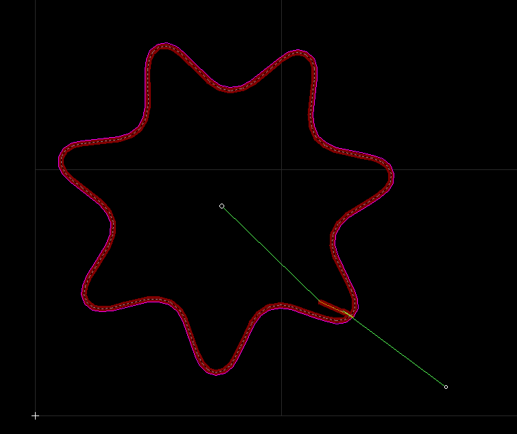
Internal cut preview:
External cut preview:
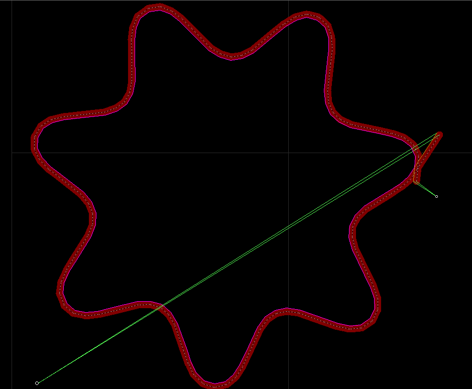
You can see where the kerf will be positionned relatively to the original path, depending of if the software considers it's an internal or external shape. You can also clearly see the small cut corresponding to the moment the waterjet enters progressively the material, either on the outside of the star (for an external cut) or the inside of the star (for an internal cut).
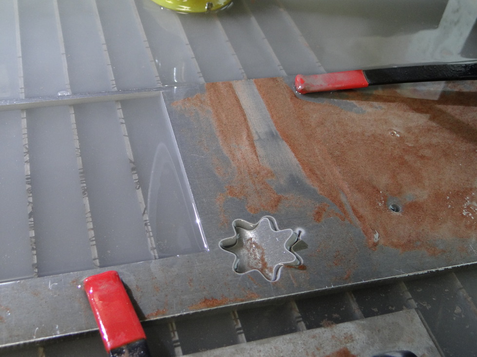
Stoneware internal cut
I thus did an internal cut in my stoneware plate. I failed a few times: first I set the quality 4, which was too slow and led the stoneware to crack. Then I used the quality 1, which may have not been sufficiant, but the problem was probably mainly that I didn't have enough abrasive sand.
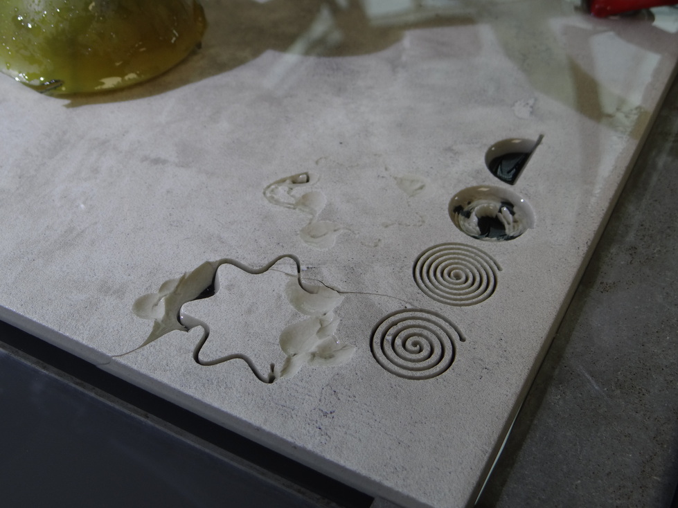
I achieved a nice cut result with the following settings:
- Material type: Italian Granite
- Material thickness: 6.5 mm
- Cutting quality : 3
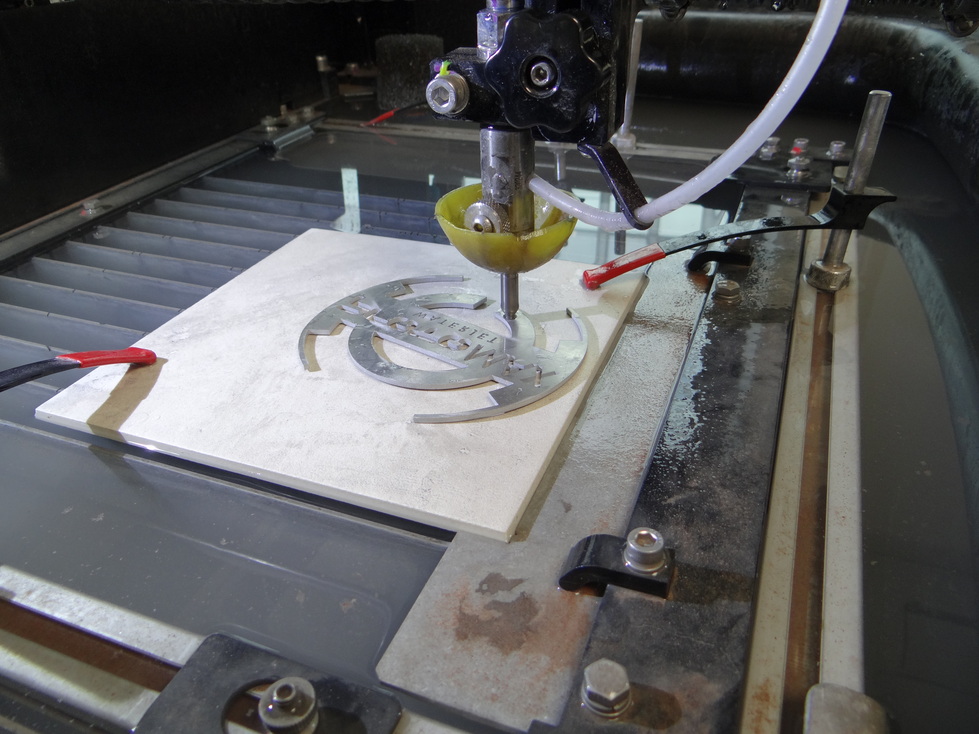
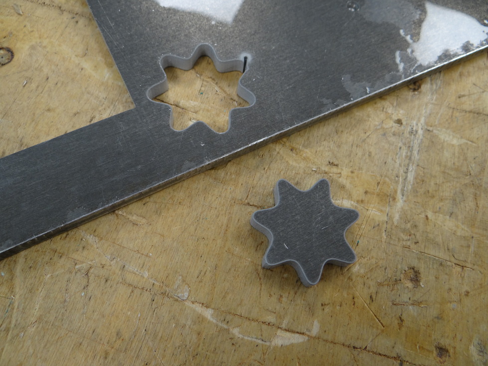
Aluminium external cut
Then I did an external cut in a piece of thick aluminium. I achieved a nice cut result from the first try with the following settings:
- Material type: Aluminium
- Material thickness: 6.5 mm
- Cutting quality : 3
Be careful not to leet your shape slip between the slats down to the bottom of the water tank! You can add some taps in your layout design if you want to avoid this.
Combining the two materials
Fit just perfectly tight. I was a bit scared to break the stoneware when pushing the aluminium shape inside but it went fine with light hammering movements. I guess that it's convenient that the stoneware is a rather soft material, allowing the aluminium inlay to force its way through.
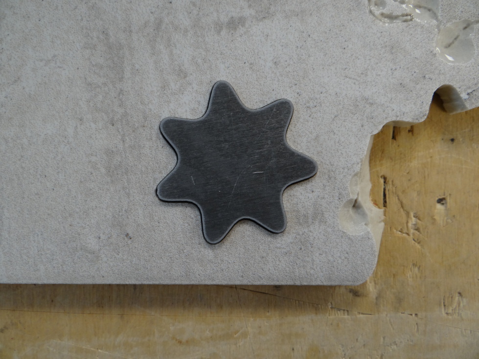
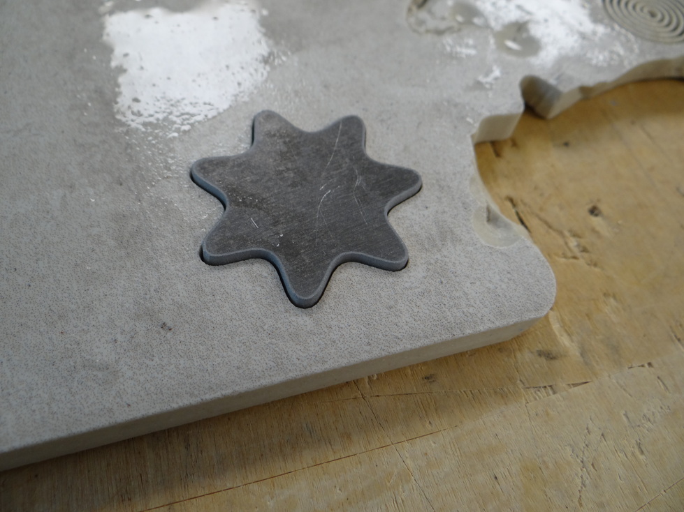
After a light hammering:
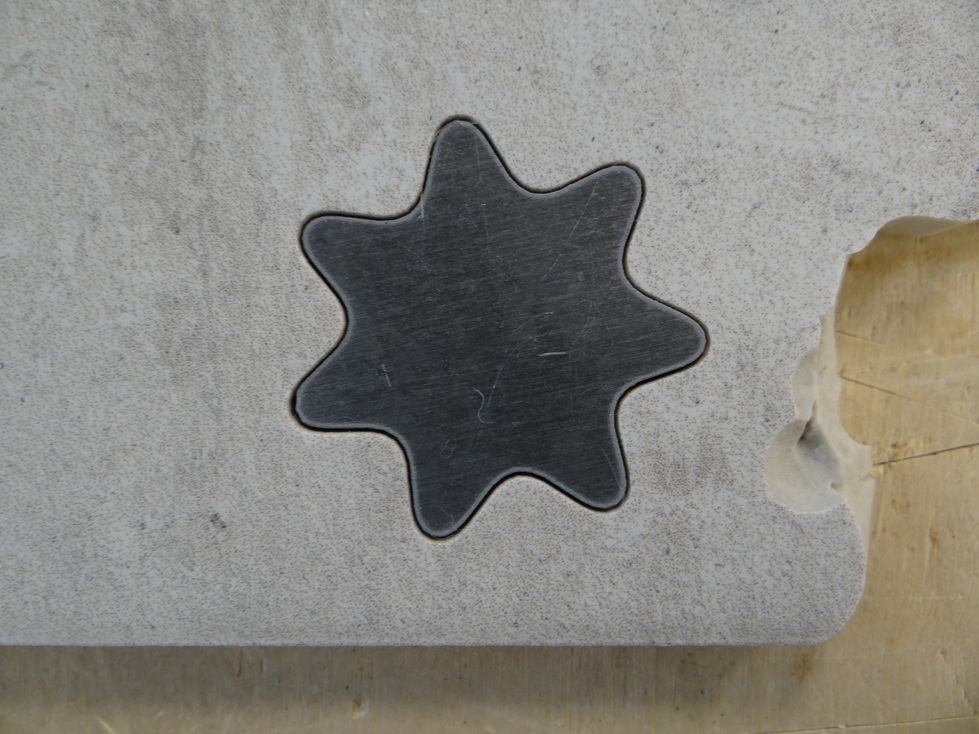
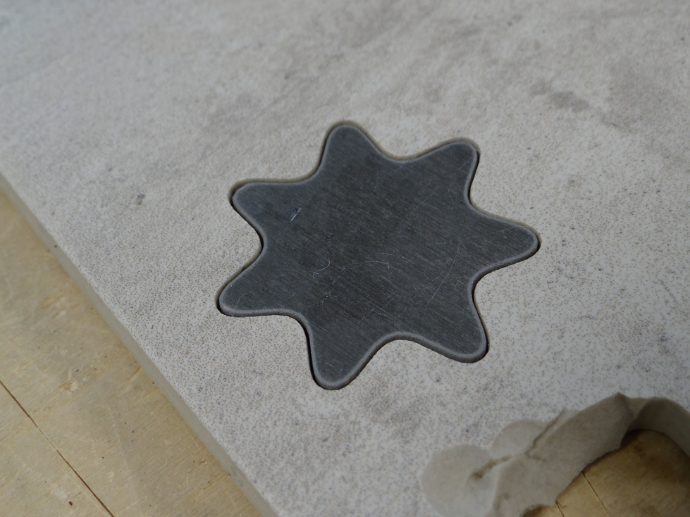
I like the result, very neat!! It works fine since my two materials have approximatively the same thickness.
I must say it's an interesting advantage of the software to take in account the machine's kerf, compared to lasercut inlays which in fact are a bit harder to set properly.
Truchet tiles pattern generation
For this week's project I'd like to create truchet tiles real tiles thanks to the waterjet cutting machine, using operations such as engraving, cutting and multi-material inlays.
Truchet tiles
Let's start with the definition given by Wikipedia (images taken from wikipedia too):
In information visualization and graphic design, Truchet tiles are square tiles decorated with patterns that are not rotationally symmetric. When placed in a square tiling of the plane, they can form varied patterns, and the orientation of each tile can be used to visualize information associated with the tile's position within the tiling.
Truchet tiles were first described in a 1704 memoir by Sébastien Truchet entitled "Mémoire sur les combinaisons", and were popularized in 1987 by Cyril Stanley Smith.
The tile originally studied by Truchet is split along the diagonal into two triangles of contrasting colors. The tile has four possible orientations.
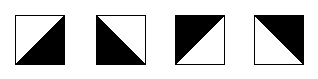
Here are some examples of surface filling made tiling such a pattern:

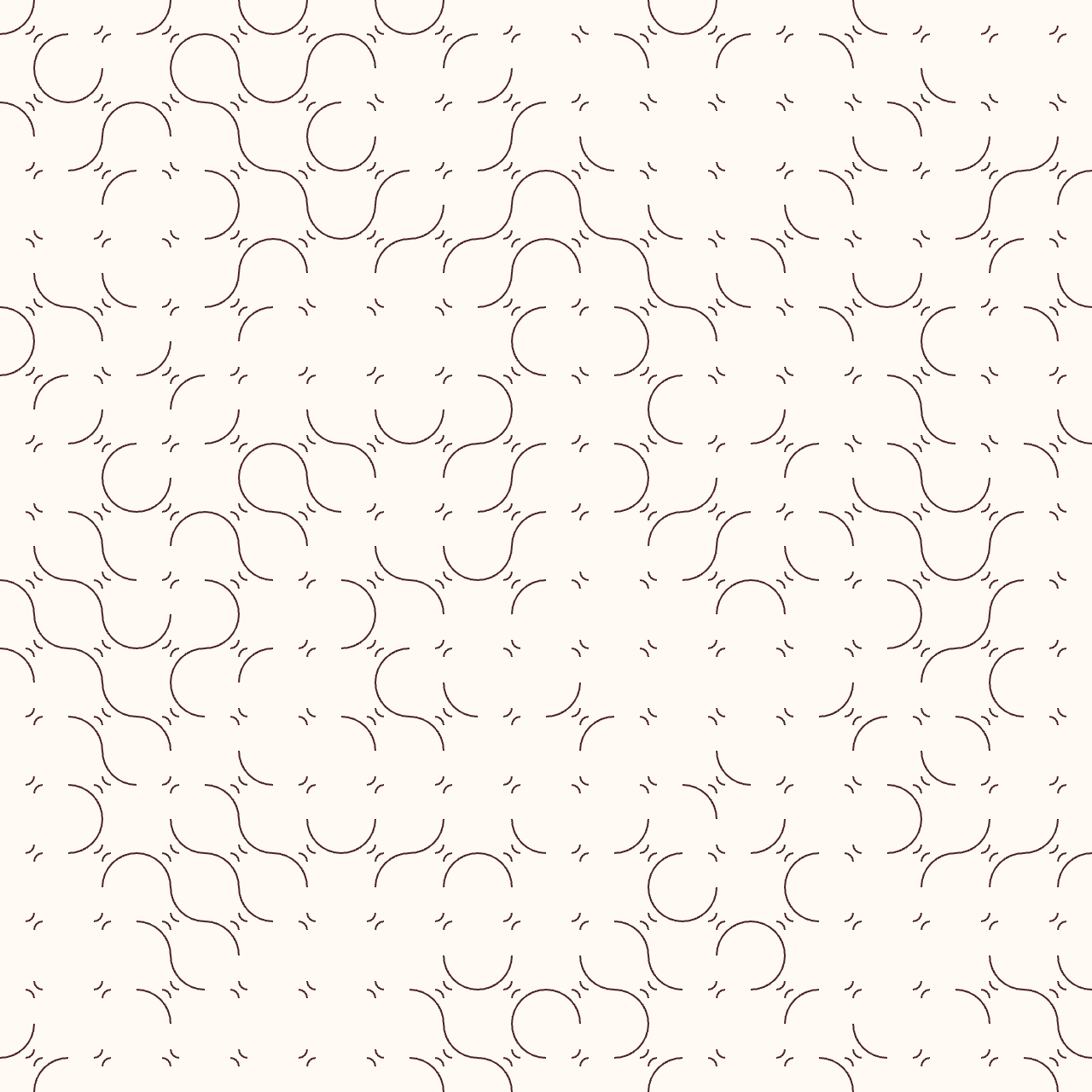
A second common form of the Truchet tiles, due to Smith (1987), decorates each tile with two quarter-circles connecting the midpoints of adjacent sides. Each such tile has two possible orientations. It's more the type of tiles I will use this week.


Which generates that type of tiling:

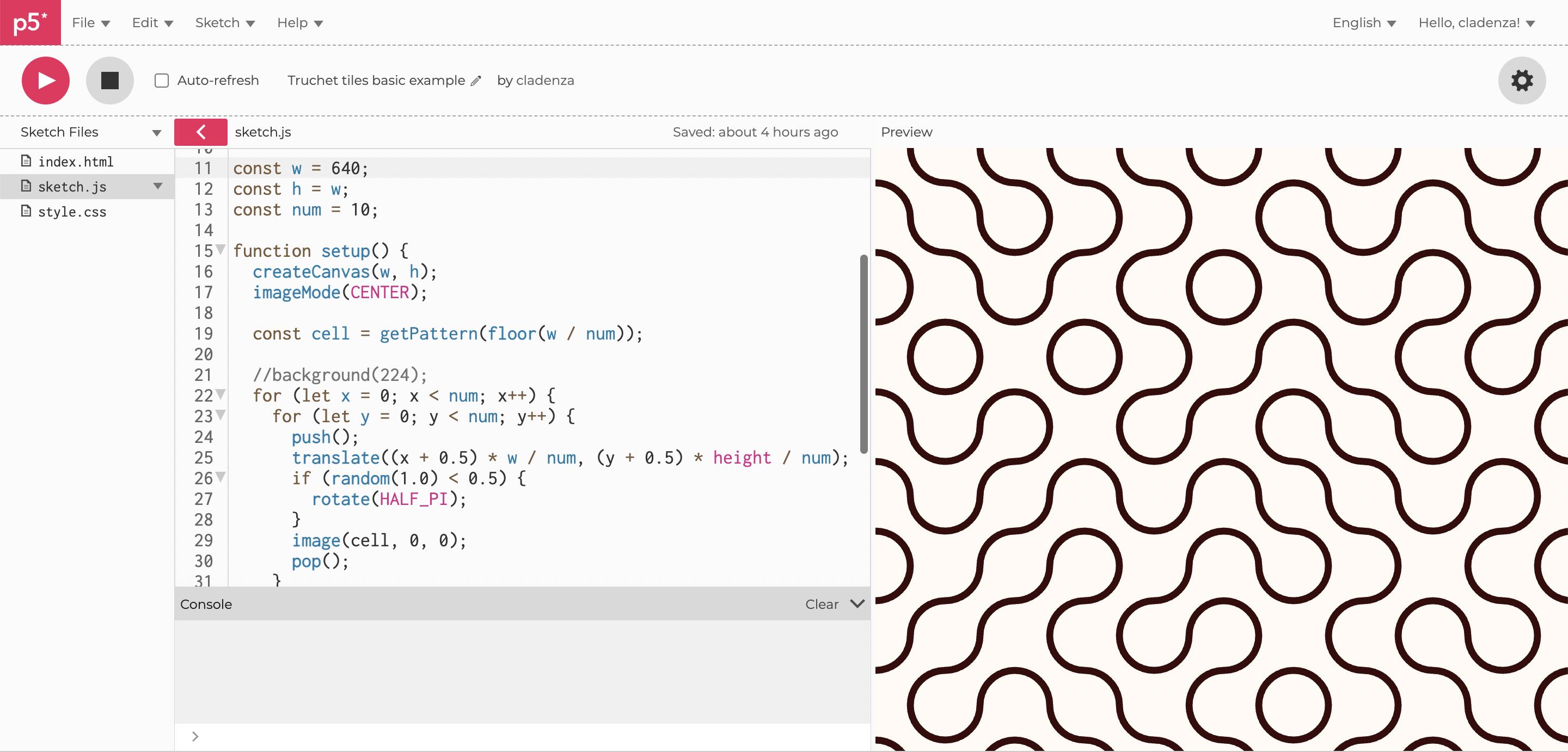
p5.js editor
p5.js is a JavaScript library for creative coding, with a focus on making coding accessible and inclusive for artists, designers, educators, beginners, ... It is free and open-source. (See p5js.org homepage)
The p5.js editor allows you to write a javascript sketch relying on the p5.js library, to compile it and visualize the result of this sketch. It's often used to generate 2D graphics, animated or not, sometimes interactive (for example reacting to the mouse movement), and it can also generate sound or create 3D images.
This sketch.js is hosted online, along with an index.html file allowing us to see the result of the sketch directly in the browser, and a style.css file if we need to style the page. You can also upload assets such as images or sound files. To see the filers and assets of the project, click on the > symbol net to the sketch.js file name, here highlighted in pink. It opens the content of the project's folder.
I am a beginner in p5.js. I had only one experience playing around with p5.js a few years ago, to make a graphic animation promoting the concert of my choir ensemble. I remixed it to embed it here but the dimensions are a bit off compared to the original sketch. It is based on a perlin noise.
I also have basics knowledge in Javascript but didn't practice it for the past year.
Litterature and truchet tile example
I explored some truchet tiles examples coded either with p5.js or processing. I thus discovered the very interesting projects open database OpenProcessing, and a lot of interesting blog articles.
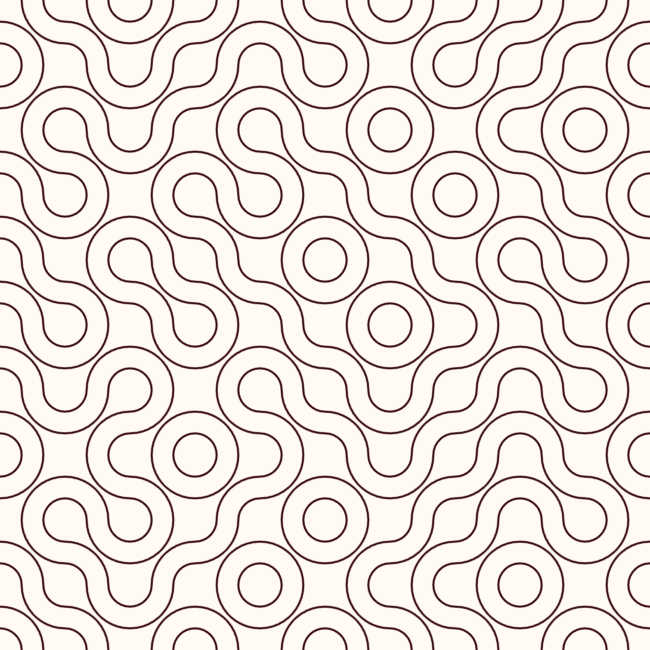
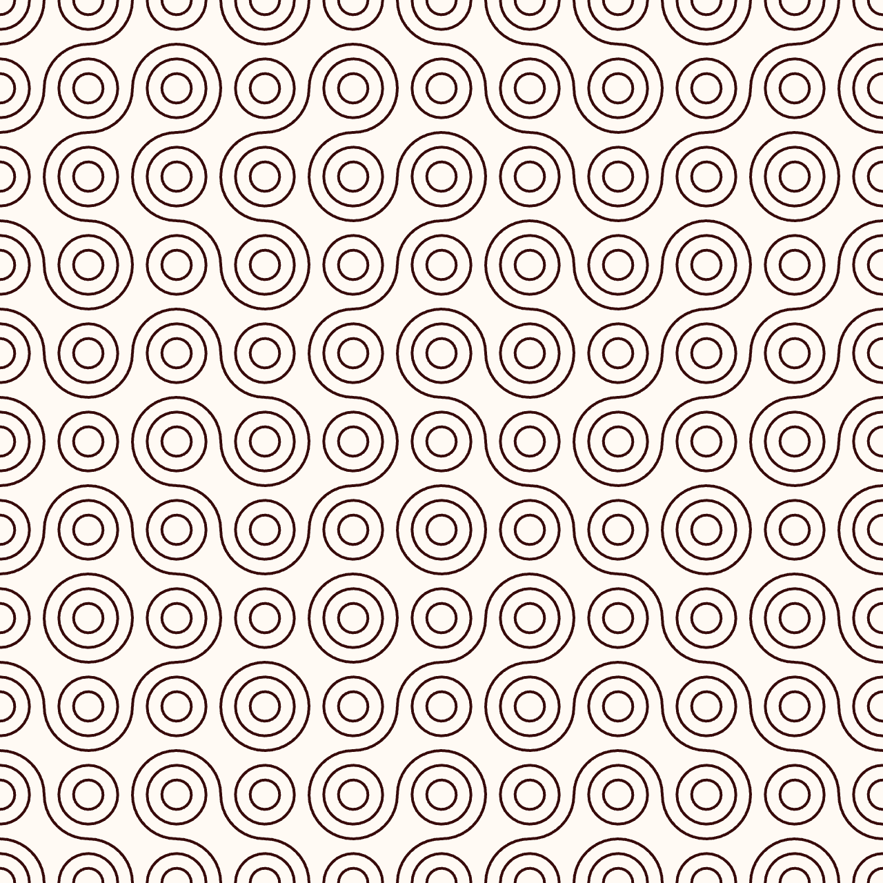
To start playing around with truchet tiles, I used the example provided by deconbatch on their blog (see original article and code). These truchet tiles are based on the Smith version with the circles arcs.
Here is the js sketch, that I simply adapted for colors:
/*
* Truchet Tiling example code
* based on the sketch of @deconbatch
* @version 0.1
* created 2022.02.28
* license CC0
* color and styling edit: @clara-devanz
* Fabacademy 2023
*/

const w = 640;
const h = w;
const num = 10;

function setup() {
  createCanvas(w, h);
  imageMode(CENTER);

  const cell = getPattern(floor(w / num));

  for (let x = 0; x < num; x++) {
    for (let y = 0; y < num; y++) {
      push();
      translate((x + 0.5) * w / num, (y + 0.5) * height / num);
      if (random(1.0) < 0.5) {
        rotate(HALF_PI);
      }
      image(cell, 0, 0);
      pop();
    }
  }
}

function getPattern(_size) {
  g = createGraphics(_size, _size);
  g.background(255, 250, 244);
  g.noFill();
  g.stroke(55, 10, 10);
  g.strokeWeight(_size * 0.1);
  g.circle(0, 0, _size);
  g.circle(_size, _size, _size);
  return g;
}
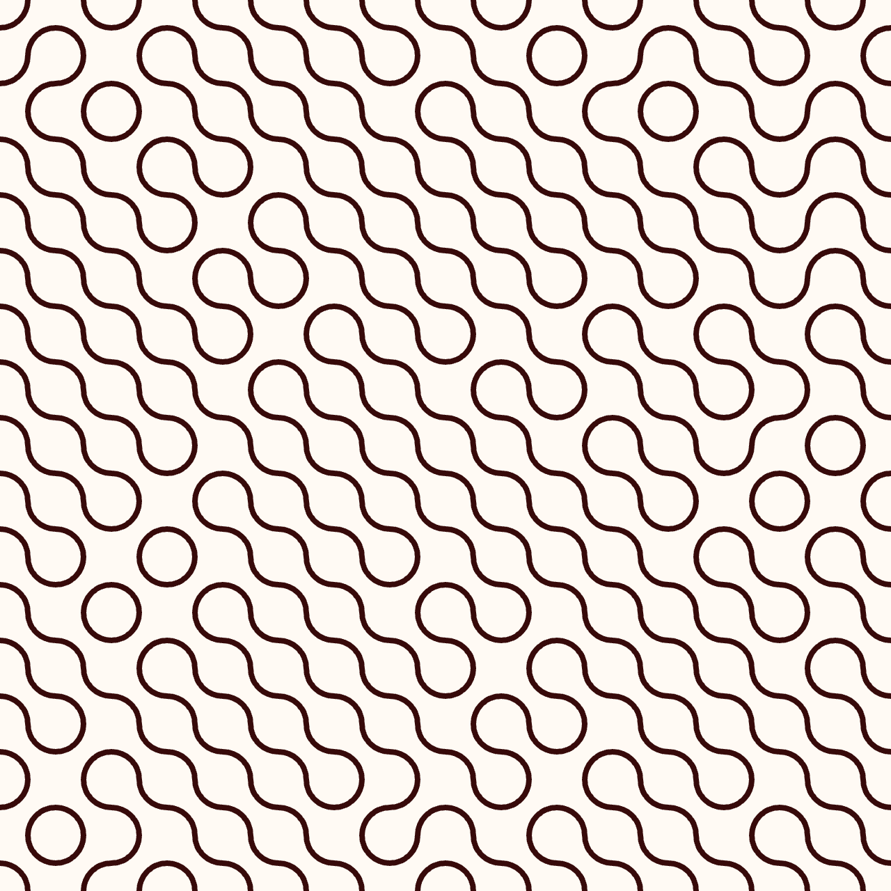
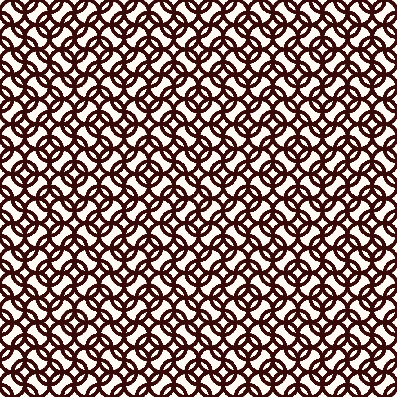
The function getPattern is called once to create the tile pattern with the function createGraphics(_size,_size). The circles are simply drawn thanks to the circle(x,y,d) function, taking 3 parameters: x and y coordinates of the center point, and diameter. Two circles with a _size diameter are created in the top left corner and the bottom right corner of the graphic. The function then returns the graphics itself. The setup function can then call the getPattern function and store the result in the constant cell. Finally the setup function execute once a script to push that result in the thanks to the image(cell, 0,0)instruction, and translate along x and y for each subdivision of the general canvas.
The generated pattern is displayed in the embedded window below. You can rerun the script, open and modify a duplicate version of this sketch in the online p5.js editor by clicking on the < / > symbol. You can also directly open the sketch in a new window.
Explorations
I modified some parameters of the sketch to get familiar with it and explore different graphic styles. I worked with 16 cells.
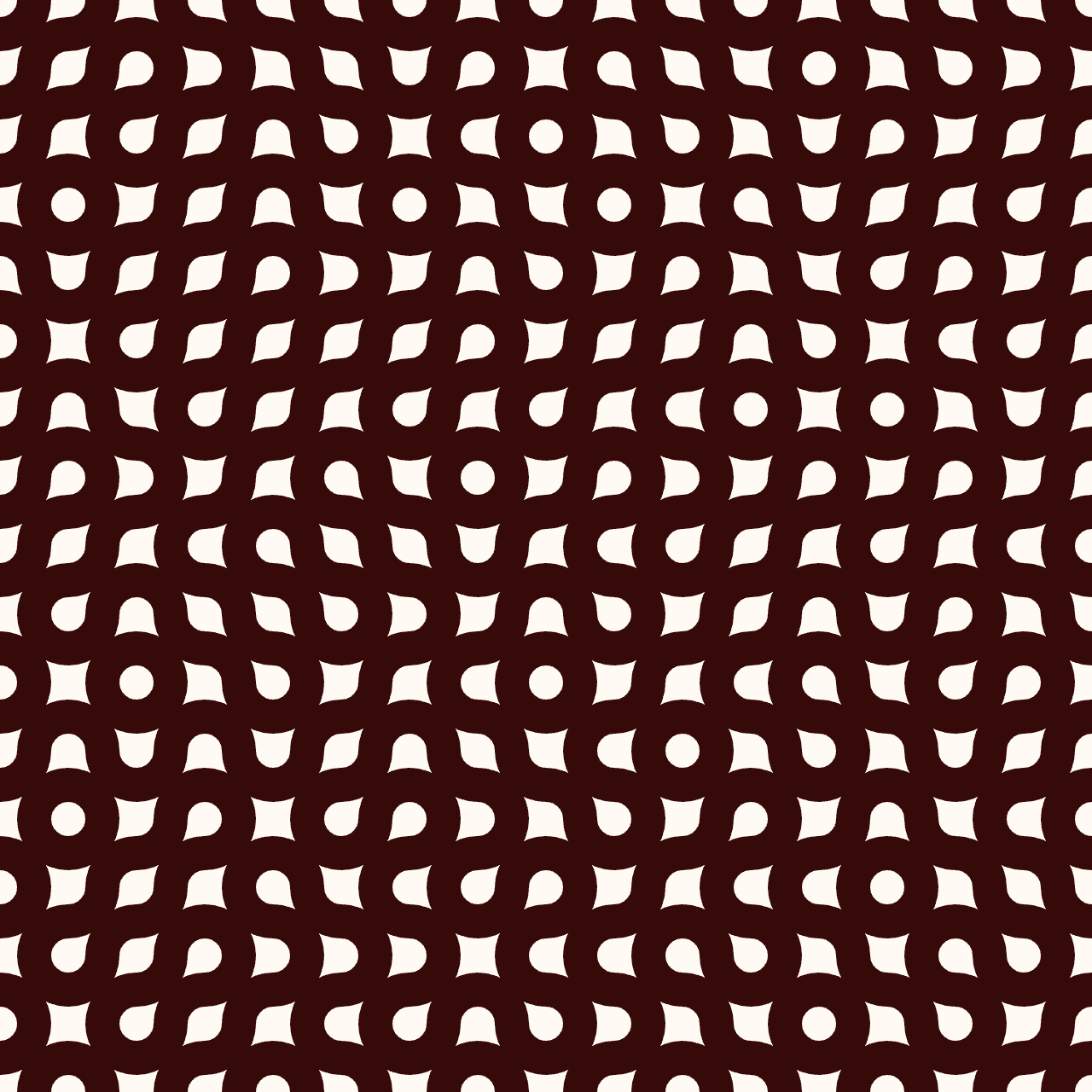
With a fill color:
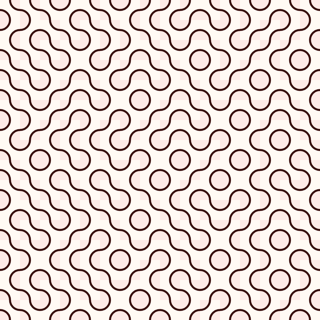
I changed the random condition: less tiles rotate.
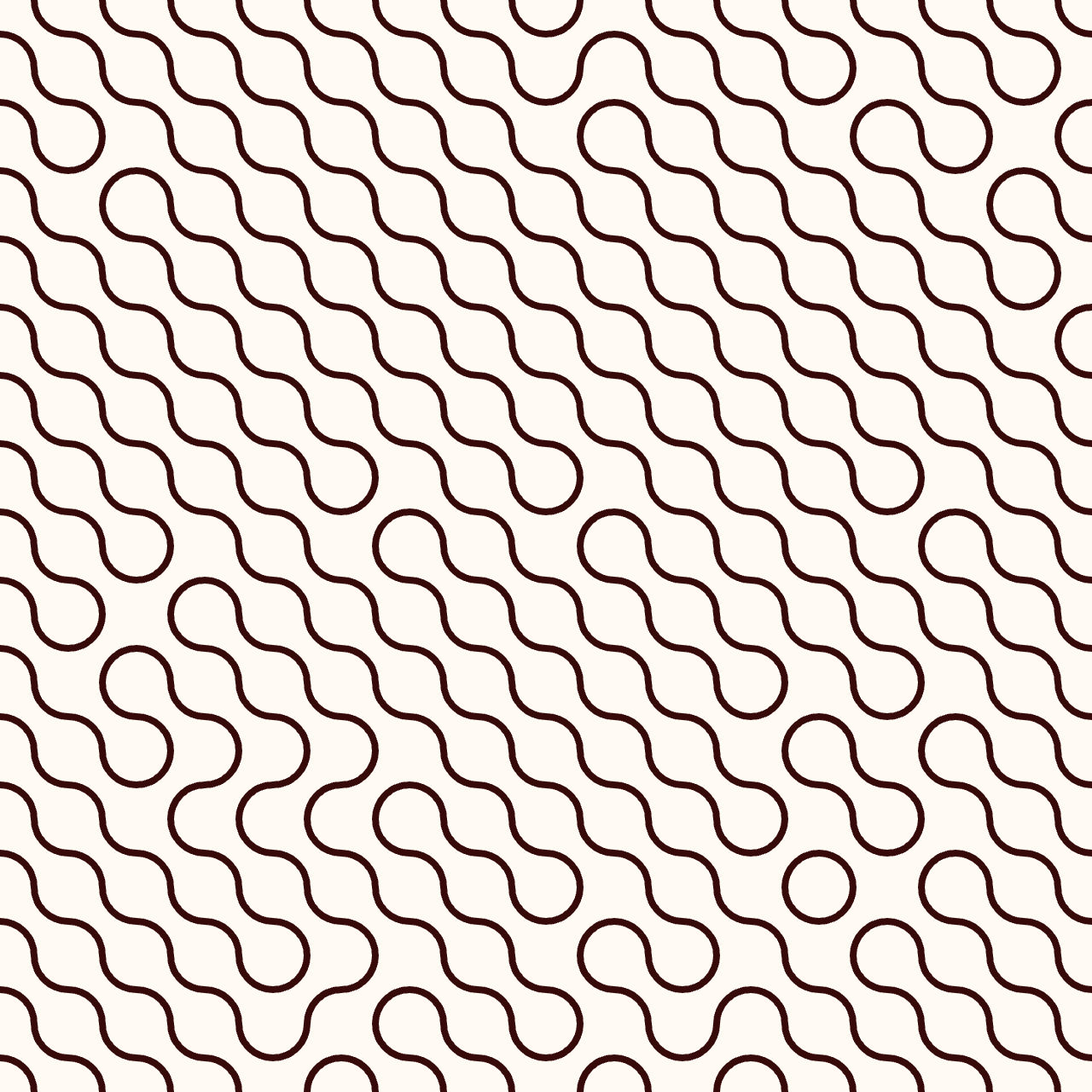
I added another circle with a _size/2 diameter:
function getPattern(_size) {
  g = createGraphics(_size, _size);
  g.background(255, 250, 244);
  g.noFill();
  g.stroke(55, 10, 10);
  g.strokeWeight(_size * 0.15);
  g.circle(0, 0, _size);
  g.circle(_size, _size, _size);
  g.circle(_size/2, _size/2, _size);
  return g;
}
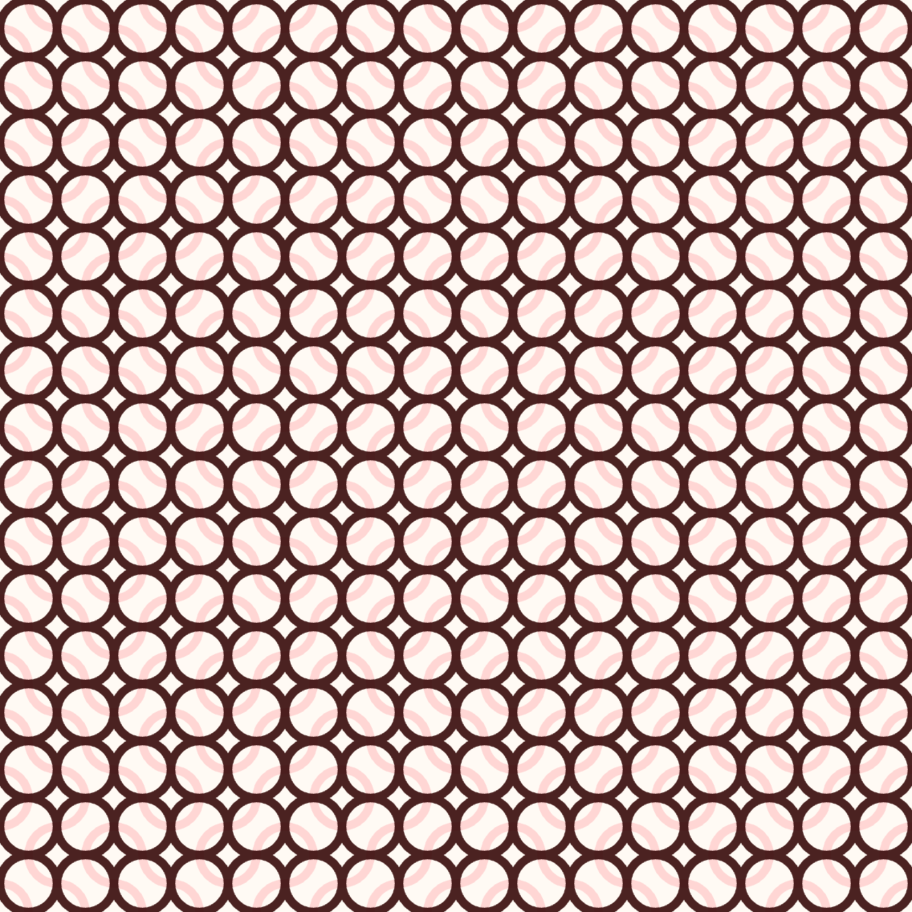
Changing the stroke color for some circles (the right example is the same sketch but with inverted colors):
function getPattern(_size) {
  g = createGraphics(_size, _size);
  g.background(255, 250, 244);
  g.noFill();
  g.stroke(55, 10, 10, 230);
  g.strokeWeight(_size * 0.15);
  //g.fill(240, 30, 60, 20);
  g.circle(0, 0, _size);
  g.circle(_size, _size, _size);
  g.stroke(255, 20, 40, 40);
  g.circle(_size/2, _size/2, _size);
  return g;
}
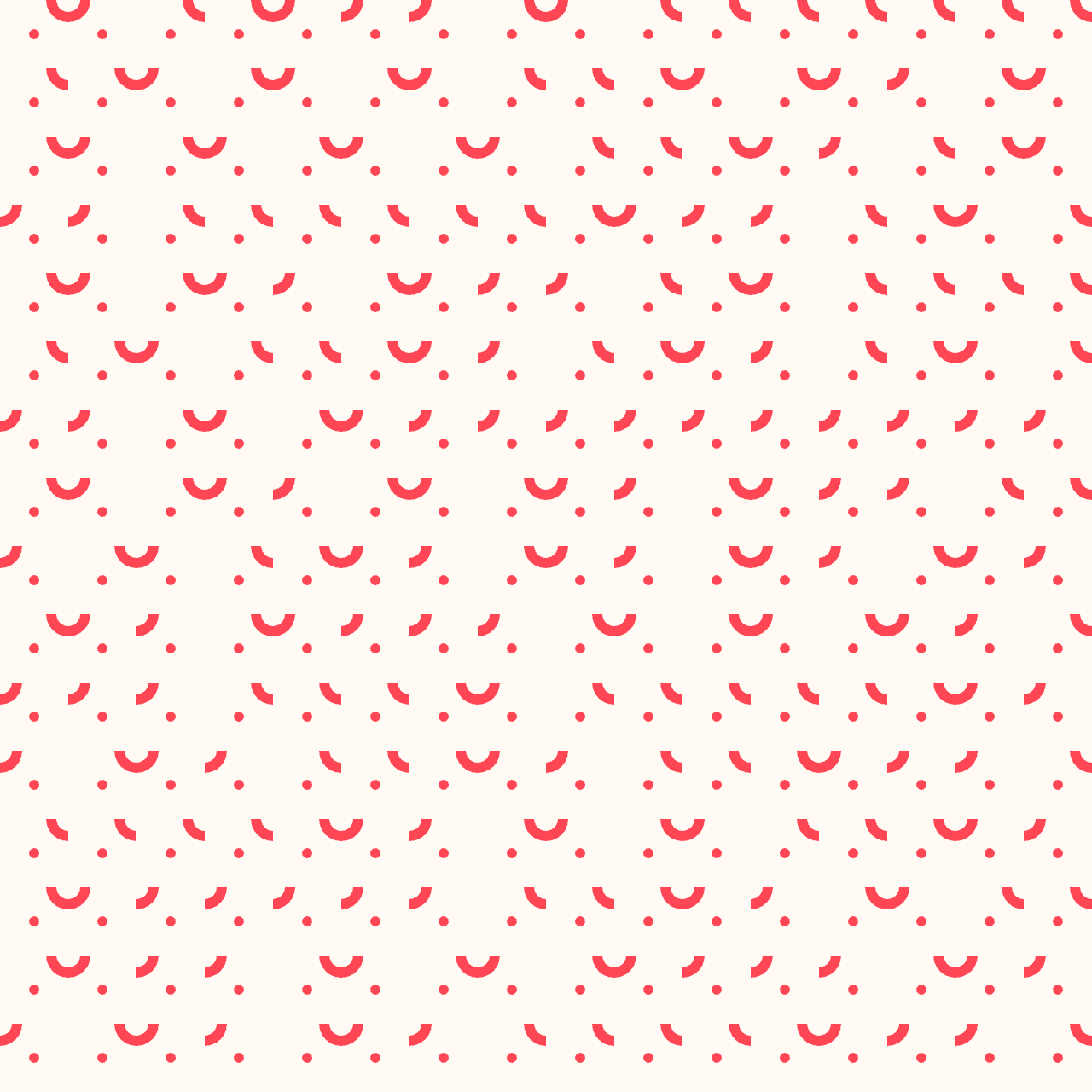
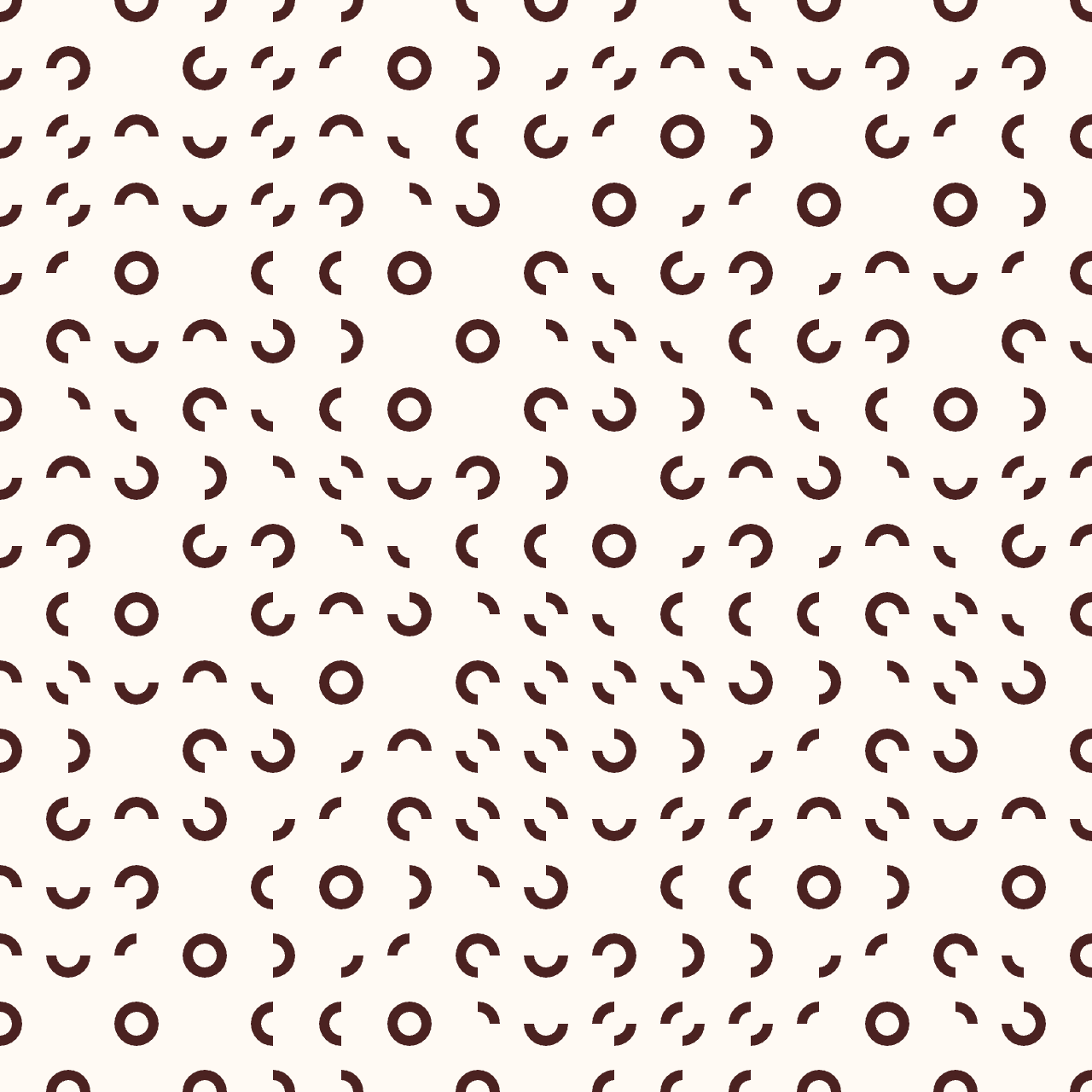
Then I kept playing around but this time the tiles aren't truchet tiles anymore: the path doesn't always coincidate on the borders, which can give nice visual styles too.
// Example 1 (top letf):

g.circle(0, 0, _size/2);
g.circle(_size/2, _size/2, 0 );

// Example 2, 3 and 4:

let r = random(_size);
g.circle(0, 0, r);
g.circle(_size, _size, r);

//3

//4
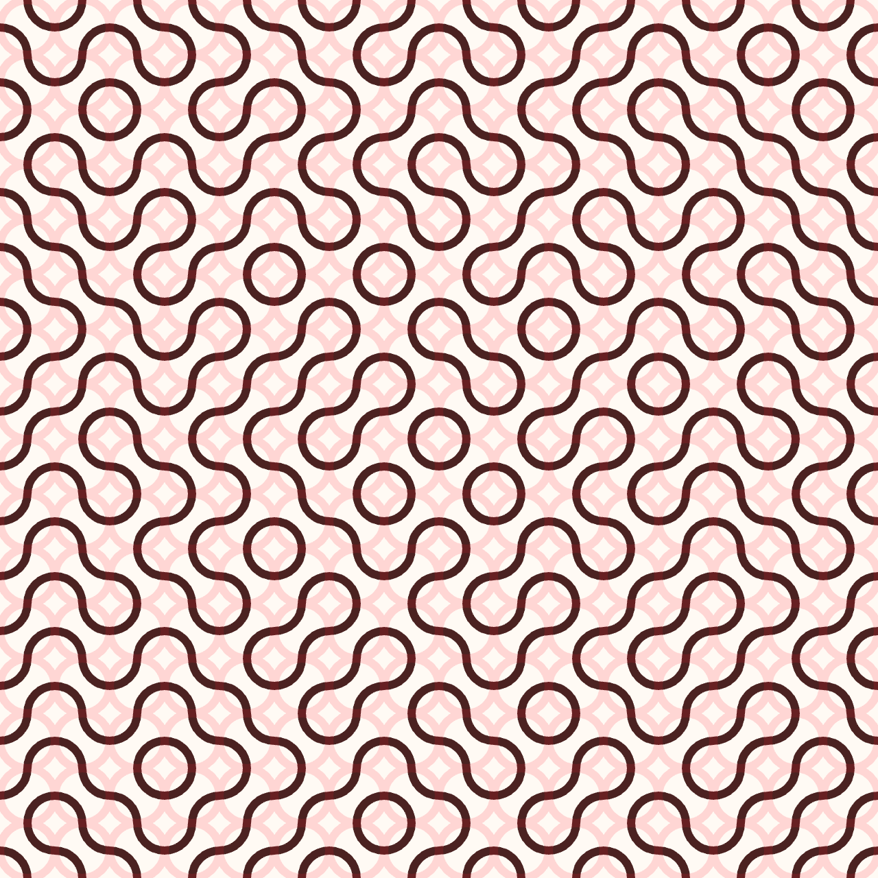
Then, inspired by the paper of Christopher Carlson describing Multi-scale truchet patterns, I created another version of the pattern, called cell_2, with smaller dimensions: const cell_2 = getPattern(floor(w / num)/2); (See more below) The setup functions alternates between cell_1 and cell_2 with a randomness factor.
I also varied the stroke width in the getPattern function.
function setup() {
  createCanvas(w, h);
  imageMode(CENTER);

  const cell_1 = getPattern(floor(w / num));
  const cell_2 = getPattern(floor(w / num)/2);

  background(255, 250, 244);
  for (let x = 0; x < num; x++) {
    for (let y = 0; y < num; y++) {
      push();
      translate((x + 0.5) * w / num, (y + 0.5) * height / num);
      if (random(1.0) < 0.5) {
        rotate(HALF_PI);
      }
      if (random(1.0) < 0.5) {
      image(cell_1, 0, 0);
      }
      image(cell_2, 0, 0);
      pop();
    }
  }
}
Variation with const cell_2 = getPattern(floor(w / num)/4);
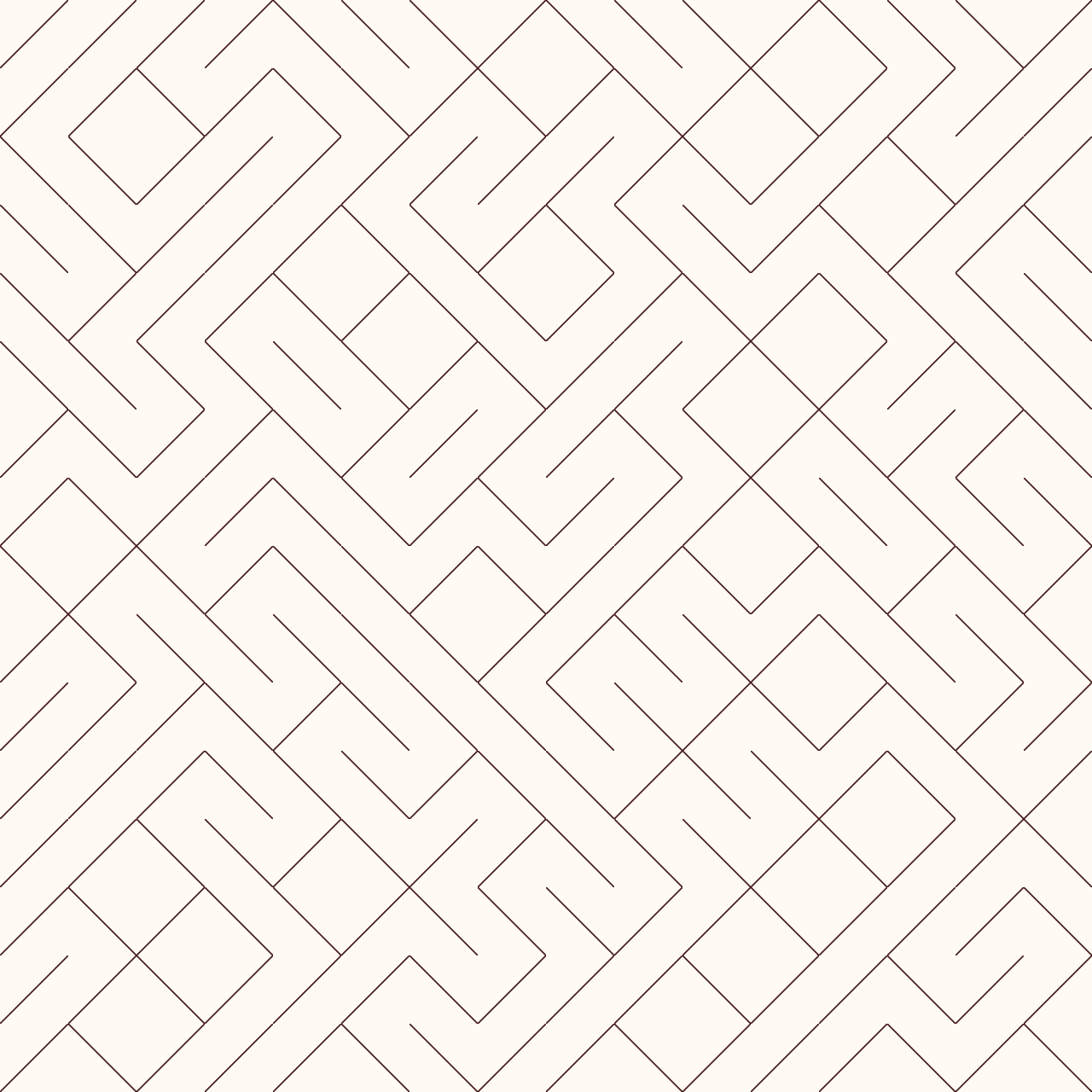
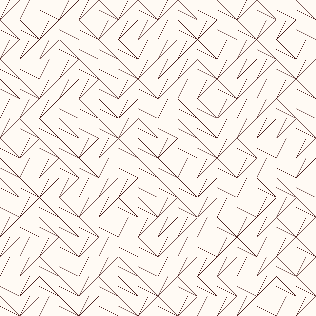
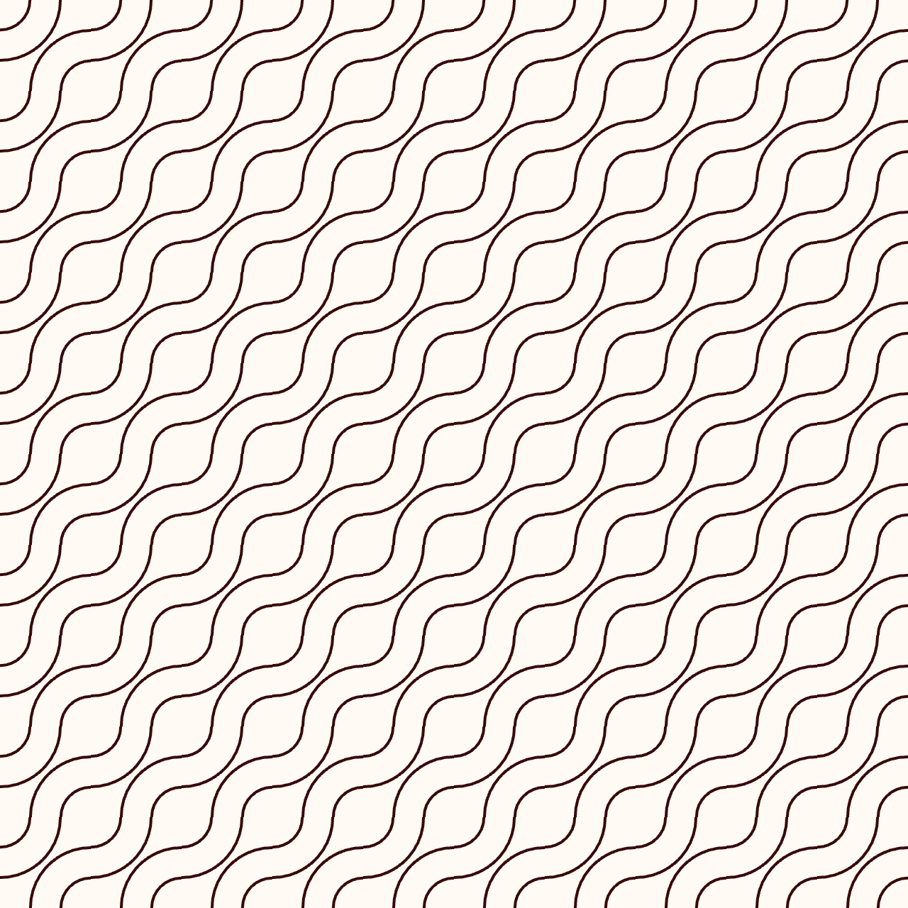
I then tried with lines instead of circles:
// Example 1 (left):
g.line(0, 0, _size, _size);
g.line(_size, _size, _size, _size);

// Example 2 (right):
g.line(0, 0, _size, _size);
g.line(_size, _size, _size, _size);
g.line(0, _size/2, _size, _size);
Multi-scale truchet patterns
After all these playful experimentations I took a look at the variation suggested by Christopher Carlson, the Multi-scale truchet patterns. You can find its explanations on his blog and in this paper.
Here's how the multidimension tiles are connected:
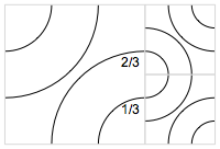
I first tried to reproduce the base tile, based on the 1/3 and 2/3 indications Carlson provides, without rotating any tiles.
function getPattern(_size) {
  g = createGraphics(_size, _size);
  g.background(255, 250, 244);
  g.noFill();
  g.stroke(55, 10, 10);
  g.strokeWeight(2);

  g.circle(0, 0, _size*0.33);
  g.circle(_size, _size, _size*0.33);

  g.circle(0, 0, _size*0.66);
  g.circle(_size, _size, _size*0.66);


  return g;
}
Here's the result, obviously wrong compared to the description of Carlson:

I thus modified the diameters and obtained continous lines as I wanted.
g.circle(0, 0, _size*0.66);
g.circle(_size, _size, _size*0.66);

g.circle(0, 0, _size*1.33);
g.circle(_size, _size, _size*1.33);
Enabling the random rotation again we have the following result:
Then I worked on doing the multi-scale aspects, that is creating cells twice smaller. It wasn't so easy to correctly position them but here's a code that worked for the placement:
const w = 640;
const h = w;
const num = 10;

function setup() {
  createCanvas(w, h);
  imageMode(CENTER);

  const cell_1 = getPattern(floor(w / num));
  const cell_2 = getPattern(floor(w / num)/2);

  let y=0;

  for (let x = 0; x < num; x=x+2) {

    for (let y=0; y < num; y=y+2){

      push();
      translate((x + 0.5) * w / num, (y + 0.5) * height / num);

    if (random(1.0) < 0.5) {
        rotate(HALF_PI);
      }

      image(cell_1, 0, 0);
      pop();

    }

    for (let y=1; y < num; y=y+2){

      push();
      translate((x + 0.25) * w / num, (y + 0.25) * height / num);

     if (random(1.0) < 0.5) {
        rotate(HALF_PI);
      }

      //rotate(HALF_PI);

      image(cell_2, 0, 0);
      pop();

      push();
      translate((x + 0.75) * w / num, (y + 0.25) * height / num);

     if (random(1.0) < 0.5) {
        rotate(HALF_PI);
      }

      //rotate(3*HALF_PI);
      image(cell_2, 0, 0);
      pop();


      push();
      translate((x+0.25) * w / num, (y + 0.75) * height / num);

     if (random(1.0) < 0.5) {
        rotate(HALF_PI);
      }

      //rotate(HALF_PI);

      image(cell_2, 0, 0);
      pop();

      push();
      translate((x+0.75) * w / num, (y + 0.75) * height / num);

     if (random(1.0) < 0.5) {
        rotate(HALF_PI);
      }

      //rotate(HALF_PI);
      image(cell_2, 0, 0);
      pop();


    }


  }


    for (let x = 1; x < num; x=x+2) {

    for (let y=1; y < num; y=y+2){

      push();
      translate((x + 0.5) * w / num, (y + 0.5) * height / num);

     if (random(1.0) < 0.5) {
        rotate(HALF_PI);
      }

      image(cell_1, 0, 0);
      pop();


    }


    for (let y=0; y < num; y=y+2){

      push();
      translate((x + 0.25) * w / num, (y + 0.25) * height / num);

     if (random(1.0) < 0.5) {
        rotate(HALF_PI);
      }

      //rotate(HALF_PI);

      image(cell_2, 0, 0);
      pop();

      push();
      translate((x + 0.75) * w / num, (y + 0.25) * height / num);

     if (random(1.0) < 0.5) {
        rotate(HALF_PI);
      }

     // rotate(3*HALF_PI);
      image(cell_2, 0, 0);
      pop();


      push();
      translate((x+0.25) * w / num, (y + 0.75) * height / num);

     if (random(1.0) < 0.5) {
        rotate(HALF_PI);
      }

      //rotate(3*HALF_PI);

      image(cell_2, 0, 0);
      pop();

      push();
      translate((x+0.75) * w / num, (y + 0.75) * height / num);

     if (random(1.0) < 0.5) {
        rotate(HALF_PI);
      }

      //rotate(3*HALF_PI);
      image(cell_2, 0, 0);
      pop();


    }
    }


}

function getPattern(_size) {
  g = createGraphics(_size, _size);
  g.background(255, 250, 244);
  g.noFill();
  g.stroke(55, 10, 10);
  g.strokeWeight(2);

  g.circle(0, 0, _size*1/3);
  g.circle(_size, _size, _size*1/3);

  g.circle(0, 0, _size*2/3);
  g.circle(_size, _size, _size*2/3);

  g.circle(0, 0, _size);
  g.circle(_size, _size, _size);

  g.circle(0, 0, _size*4/3);
  g.circle(_size, _size, _size*4/3);

  return g;
}
Multi-arcs truchet tiles
I didn't explored further the multi-scale cells as placing correctly the tiles was a bit fastidious and came back to working with one cell dimension.
// Example 1
  g.circle(0, 0, _size*1/3);
  g.circle(_size, _size, _size*1/3);

  g.circle(0, 0, _size*2/3);
  g.circle(_size, _size, _size*2/3);

  g.circle(0, 0, _size);
  g.circle(_size, _size, _size);

// Example 2

  g.circle(0, 0, _size*1/3);
  g.circle(_size, _size, _size*1/3);

  g.circle(0, 0, _size*2/3);
  g.circle(_size, _size, _size*2/3);

  g.circle(0, 0, _size);
  g.circle(_size, _size, _size);

  g.circle(0, 0, _size*4/3);
  g.circle(_size, _size, _size*4/3);
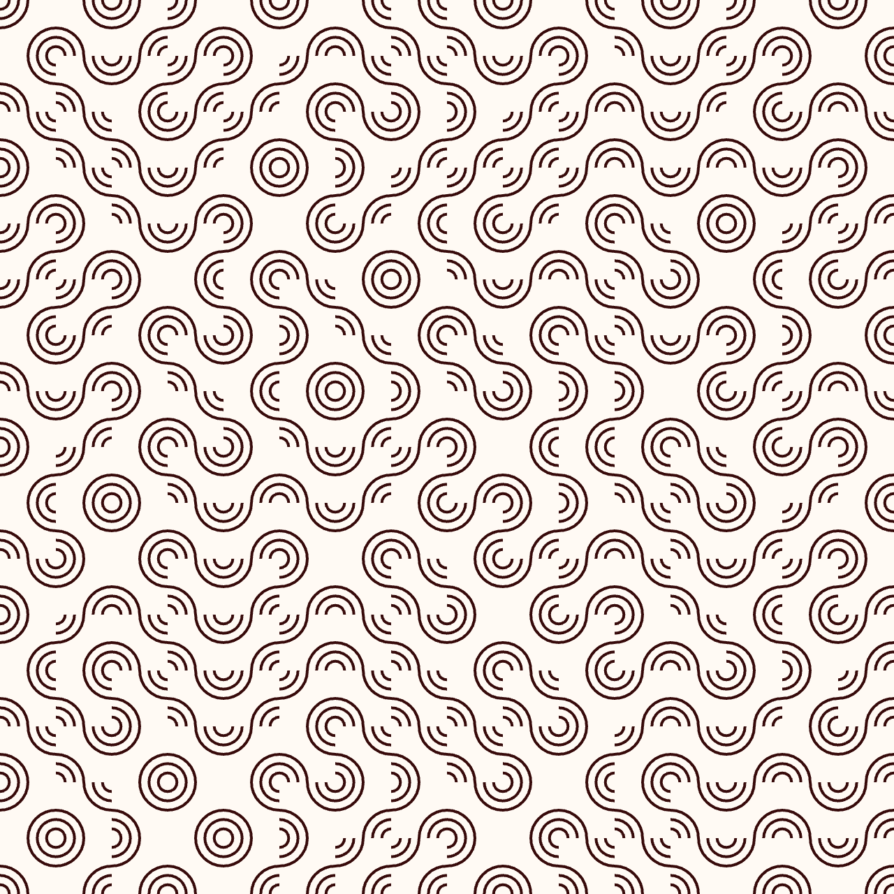
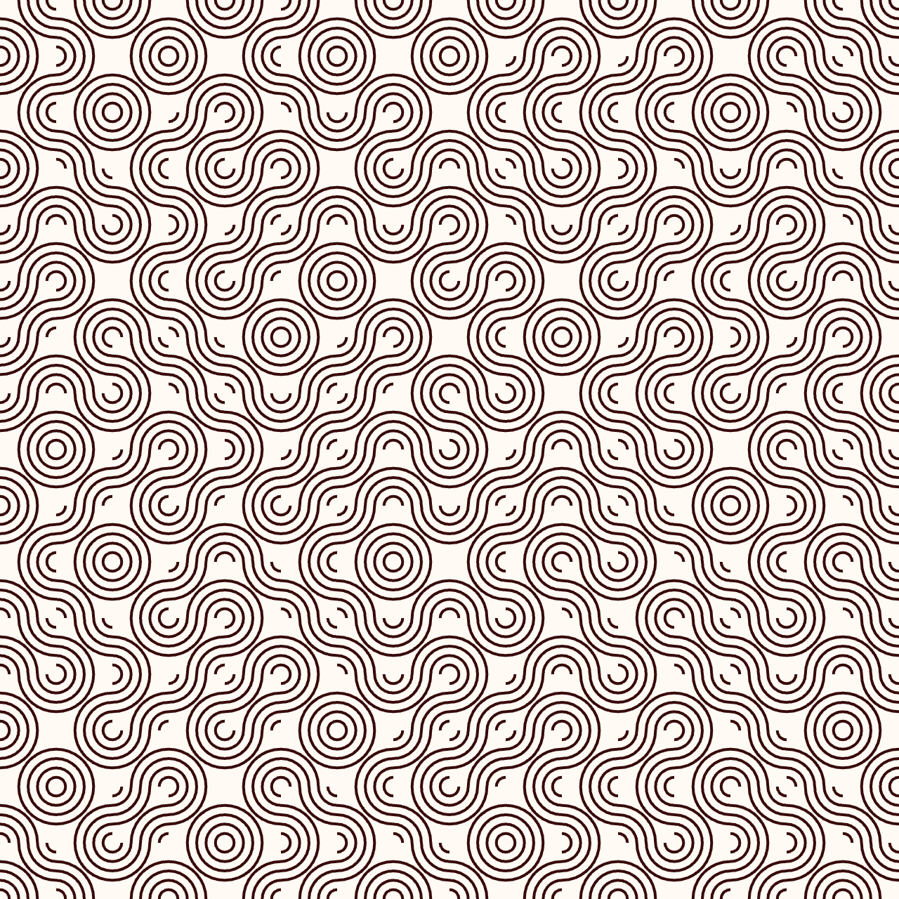
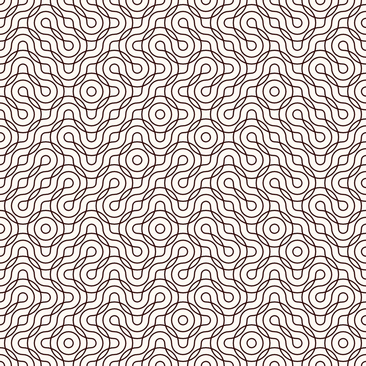
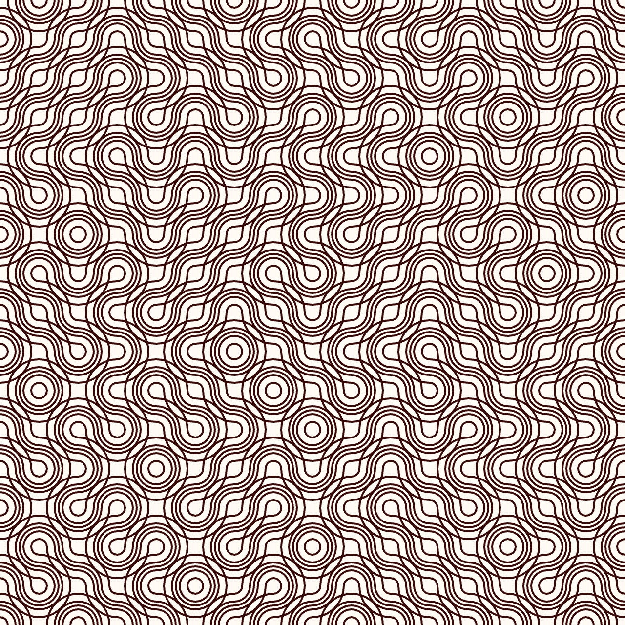
I finally understood how to choose the diameter values to have continuous lines from one tile to another: you have to choose diameter factors which are respectively symmetricals to 1. For example:
- 1/3 and 5/3
- 2/3 and 4/3
- 0.3 and 1.7
- 0.8 and 1.2
On the first example I traced 5 circles:
  g.circle(0, 0, _size*1/3);
  g.circle(_size, _size, _size*1/3);

  g.circle(0, 0, _size*2/3);
  g.circle(_size, _size, _size*2/3);


  g.circle(0, 0, _size);
  g.circle(_size, _size, _size);

  g.circle(0, 0, _size*4/3);
  g.circle(_size, _size, _size*4/3);

  g.circle(0, 0, _size*5/3);
  g.circle(_size, _size, _size*5/3);
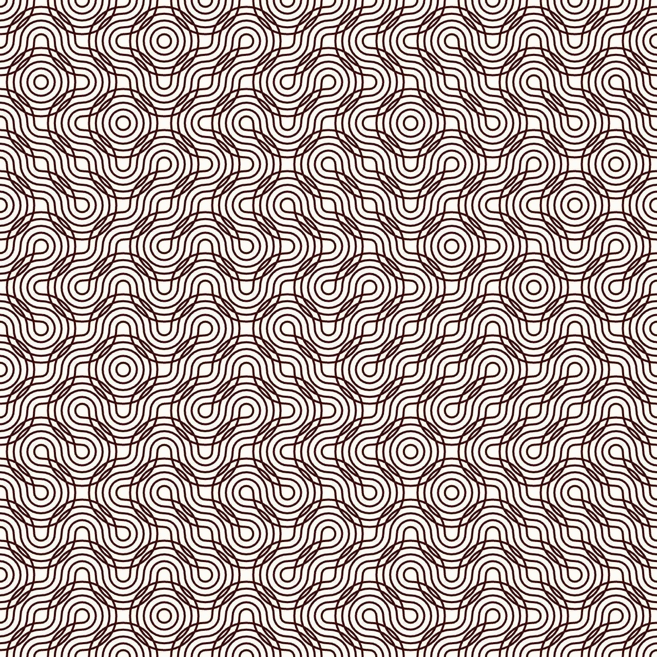
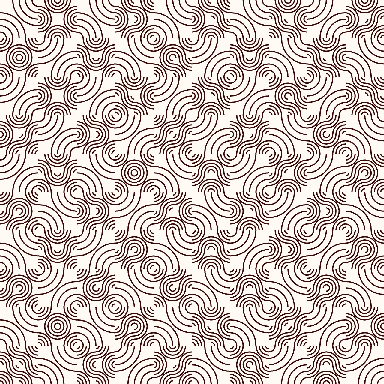
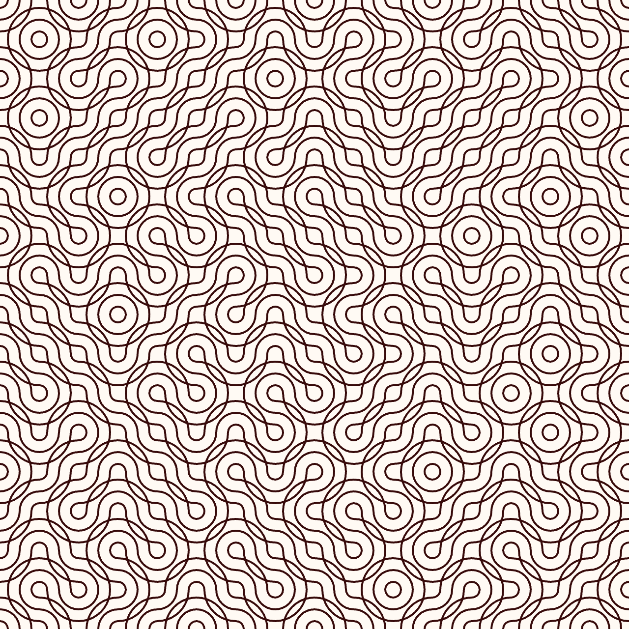
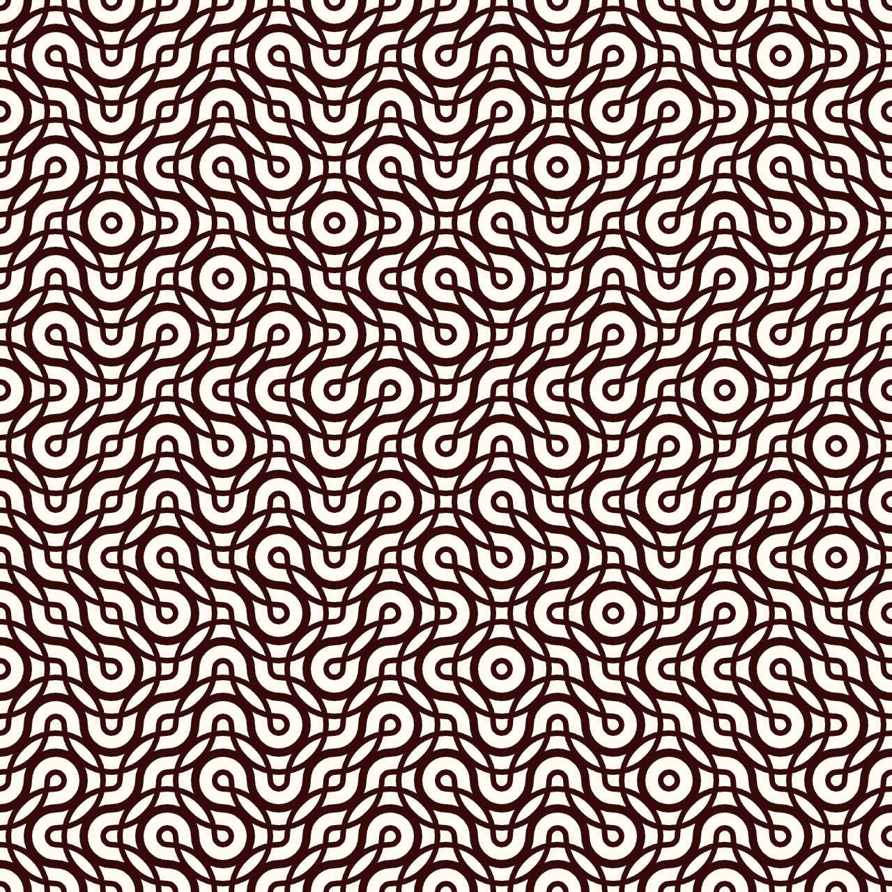
Tracing more circles:
g.circle(0, 0, _size*1/3);
g.circle(_size, _size, _size*1/3);
g.circle(0, _size, _size*1/3);
g.circle(_size, 0, _size*1/3);

g.circle(0, 0, _size*2/3);
g.circle(_size, _size, _size*2/3);
g.circle(0, _size, _size*2/3);
g.circle(_size, 0, _size*2/3);

g.circle(0, _size, _size);
g.circle(_size, 0, _size);
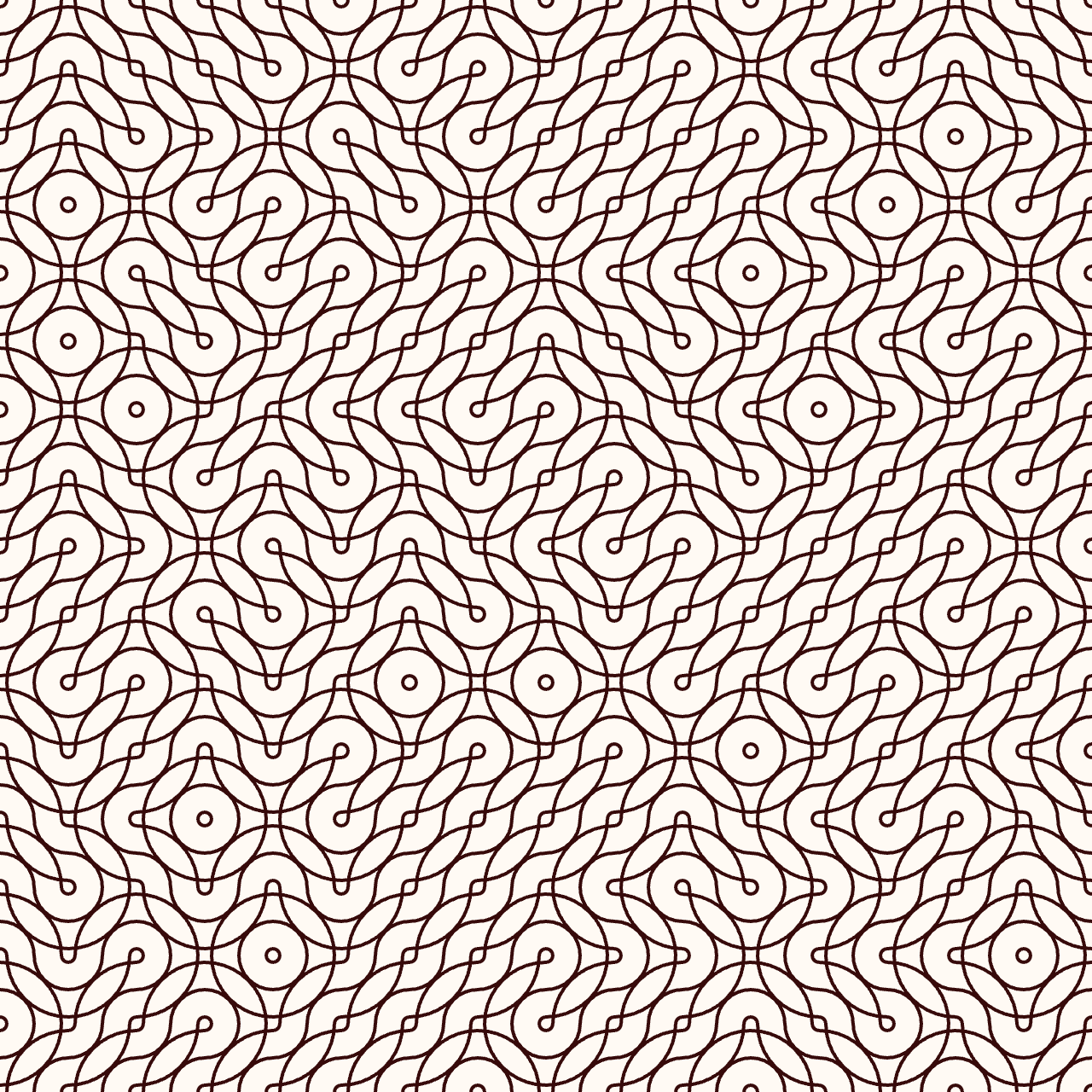
I generalized the getPattern function with a, b and c parameters defined at the beginning of my sketch:
  g.circle(0, 0, _size*a);
  g.circle(_size, _size, _size*a);

  g.circle(0, 0, _size*b);
  g.circle(_size, _size, _size*b);

  g.circle(0, 0, _size*c);
  g.circle(_size, _size, _size*c);
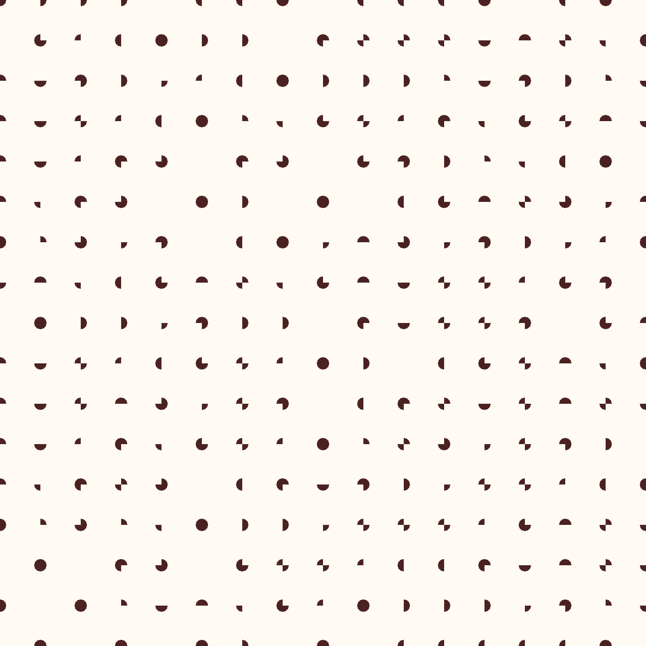
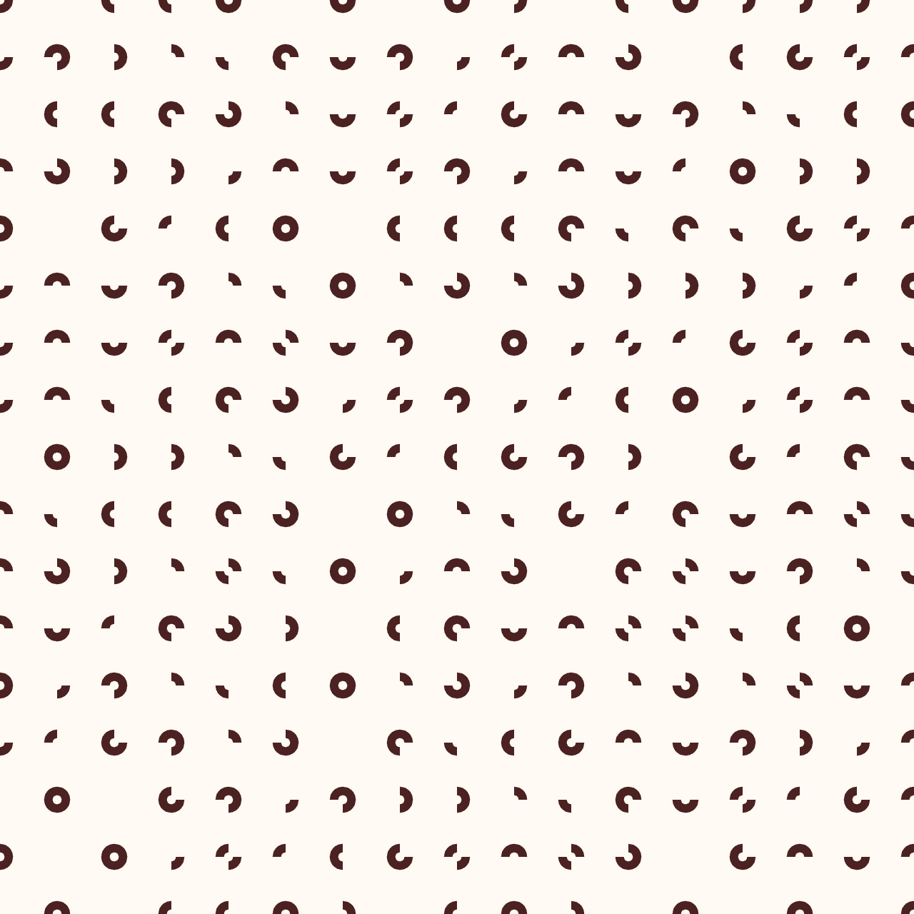
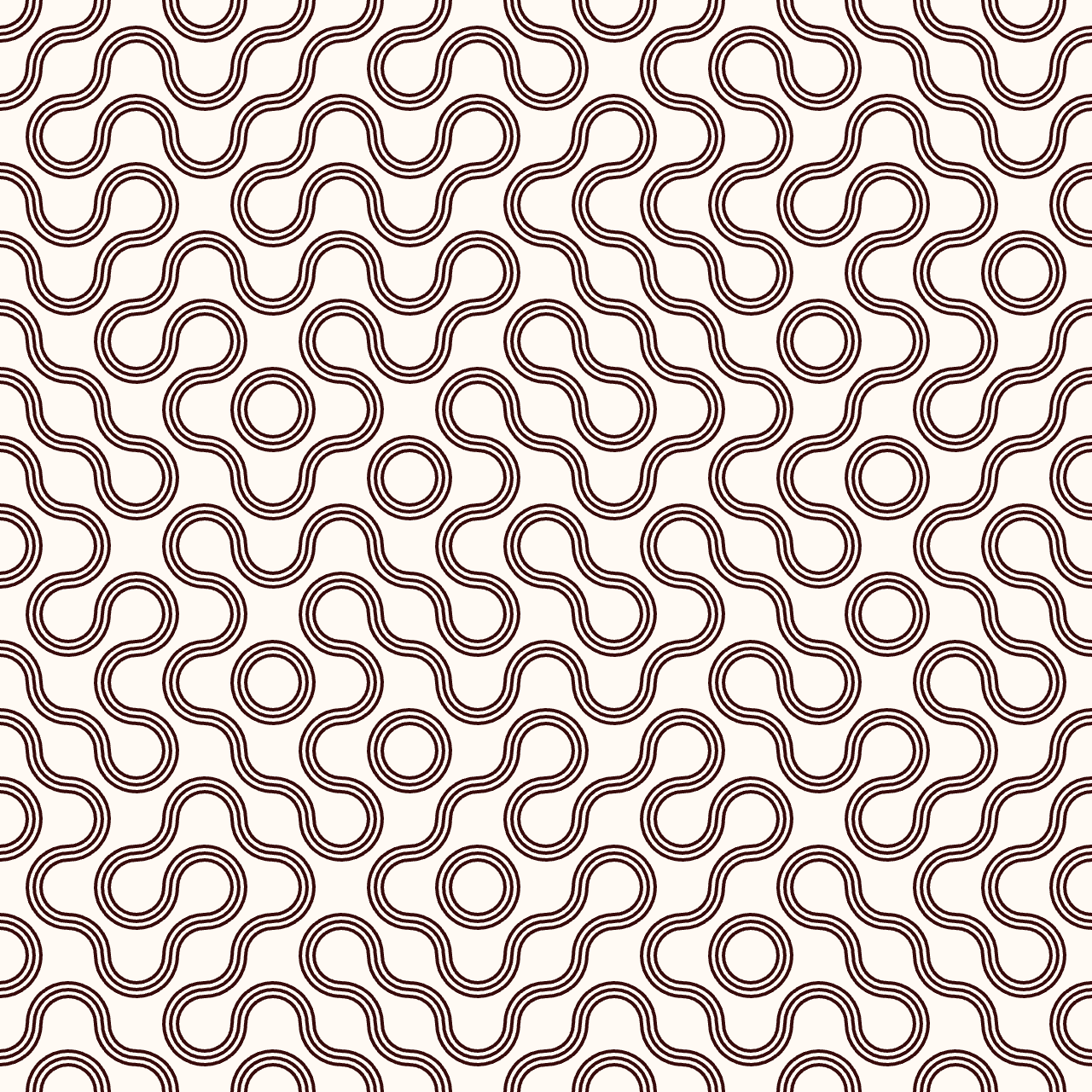
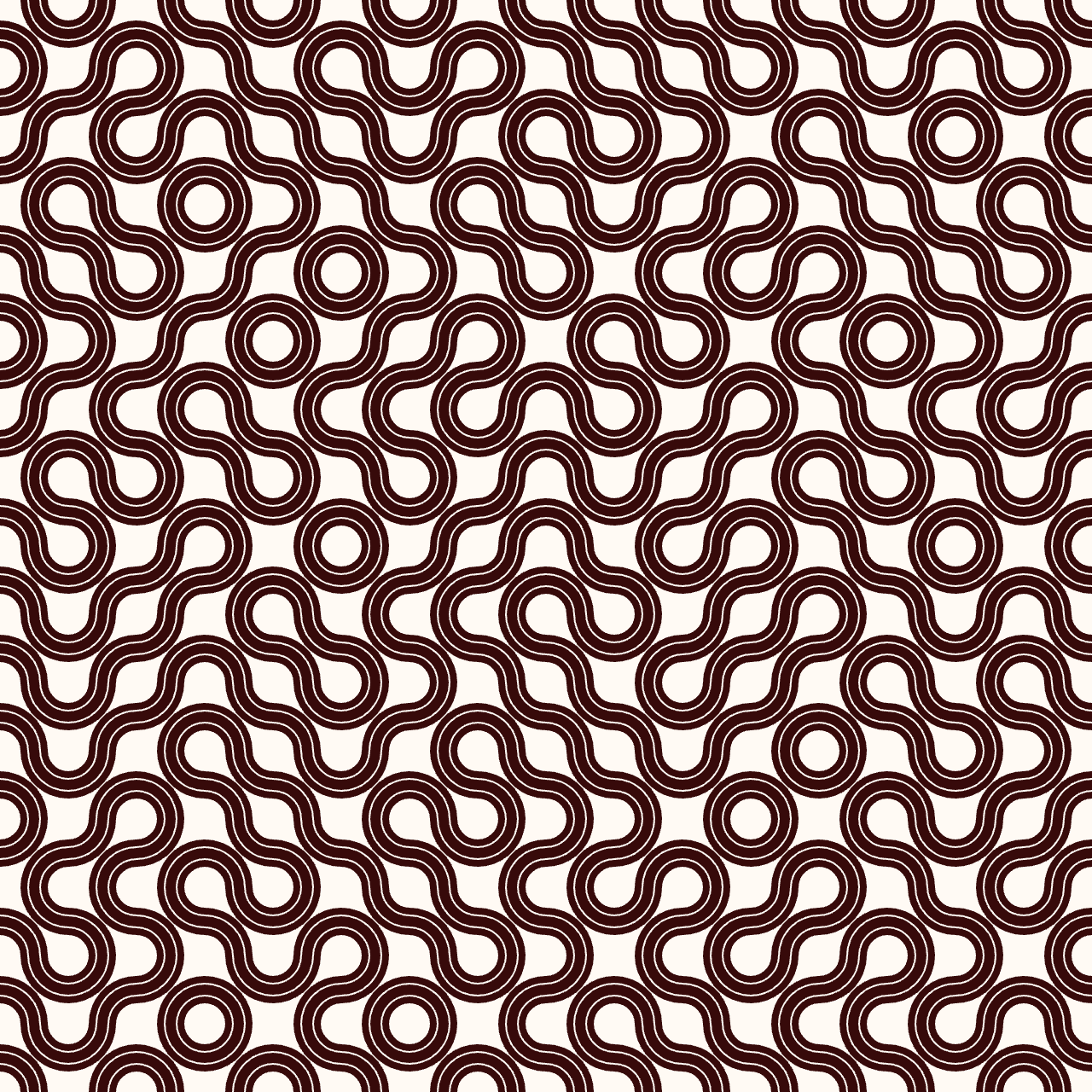
First example with a=2/3; b=1; c=4/3 :
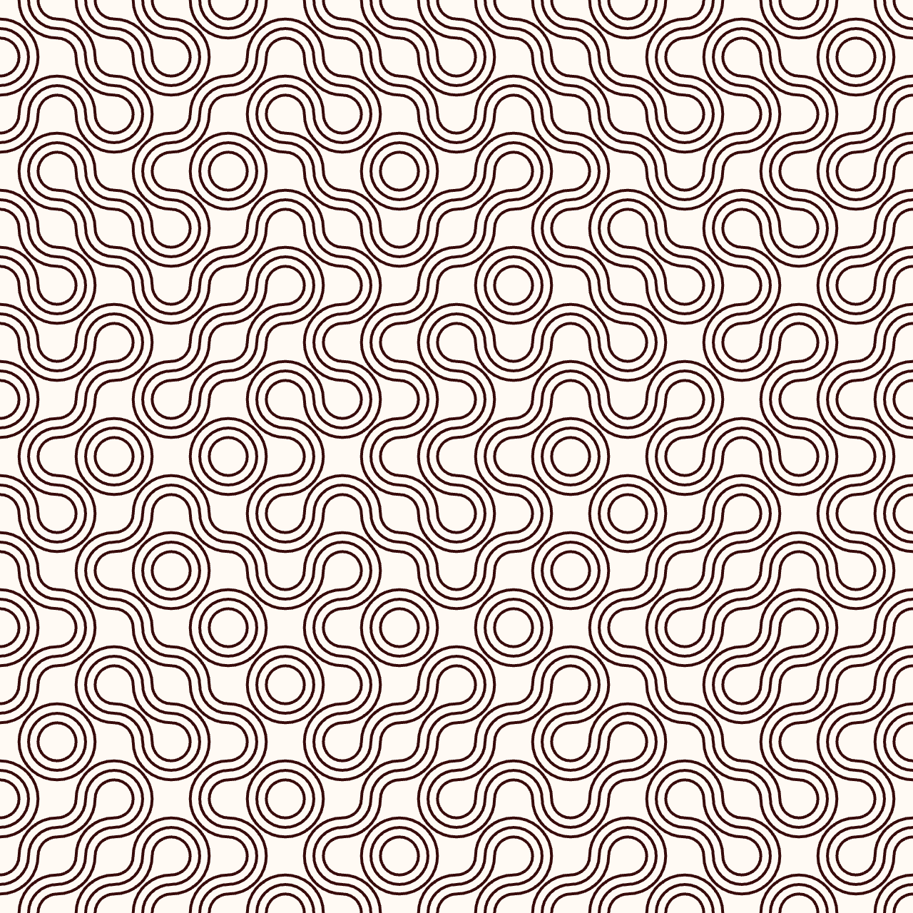
Here's an embed window of the sketch if you want to play with the parameters in the editor, that you can also open in a new window by following this link.
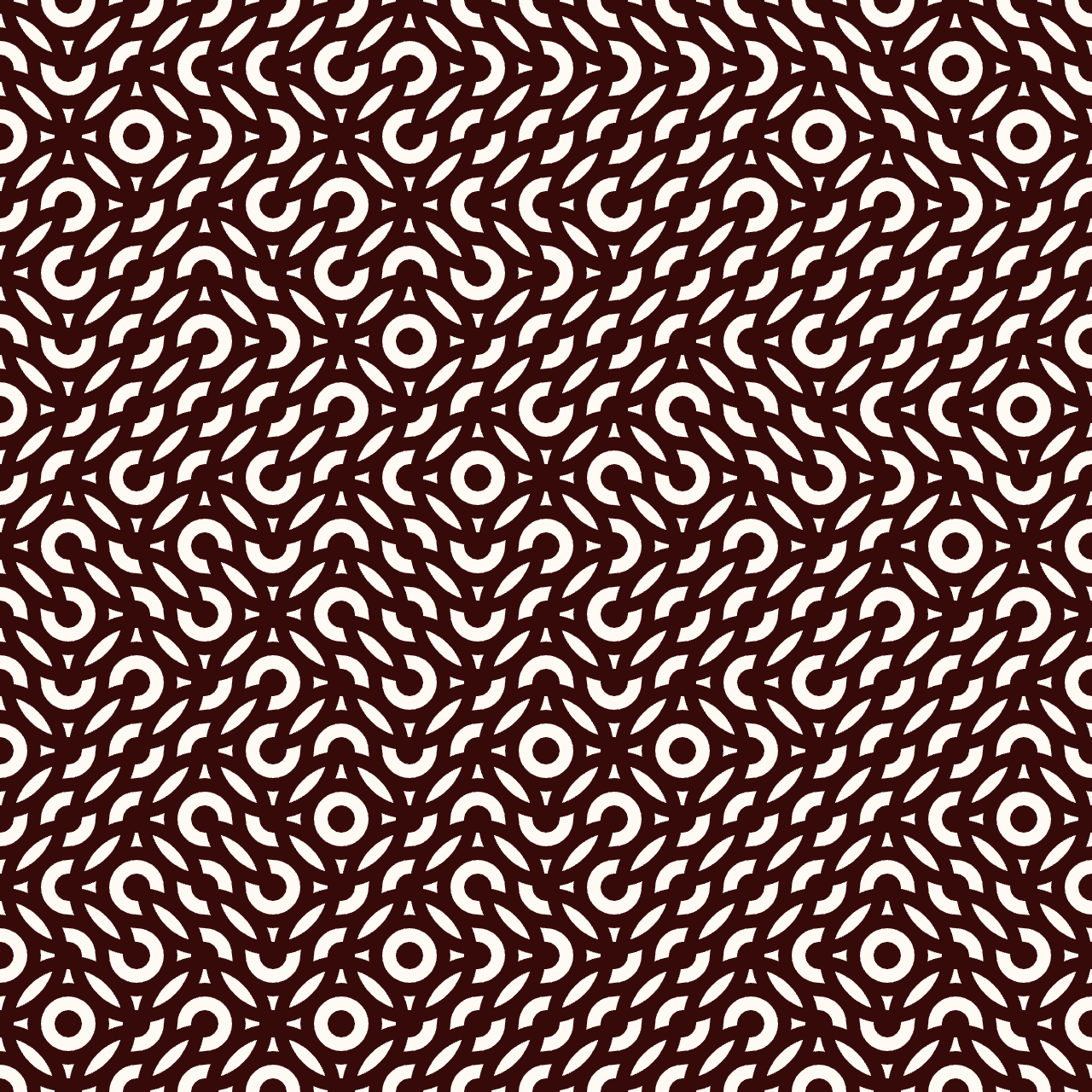
Left: a=0.4; b=1; c=1.6 / Right: a=1.2; b=1; c=0.8
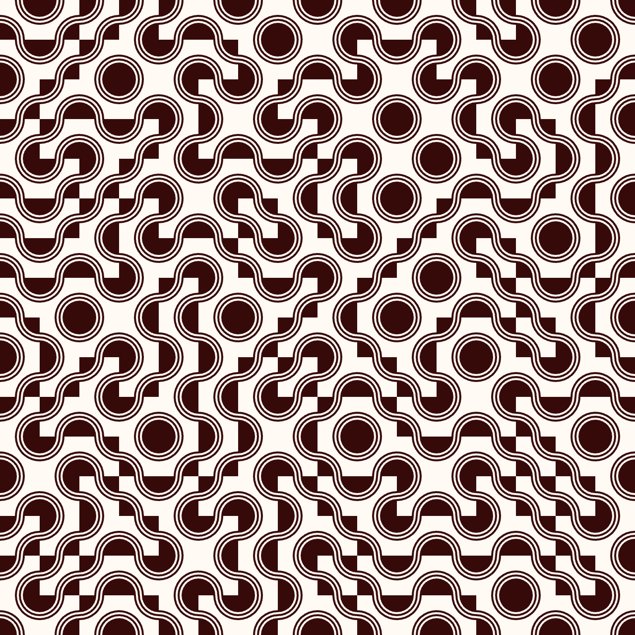
Adding filling before the circles instructions. For the right example, I inverted the background and stroke/fill color.
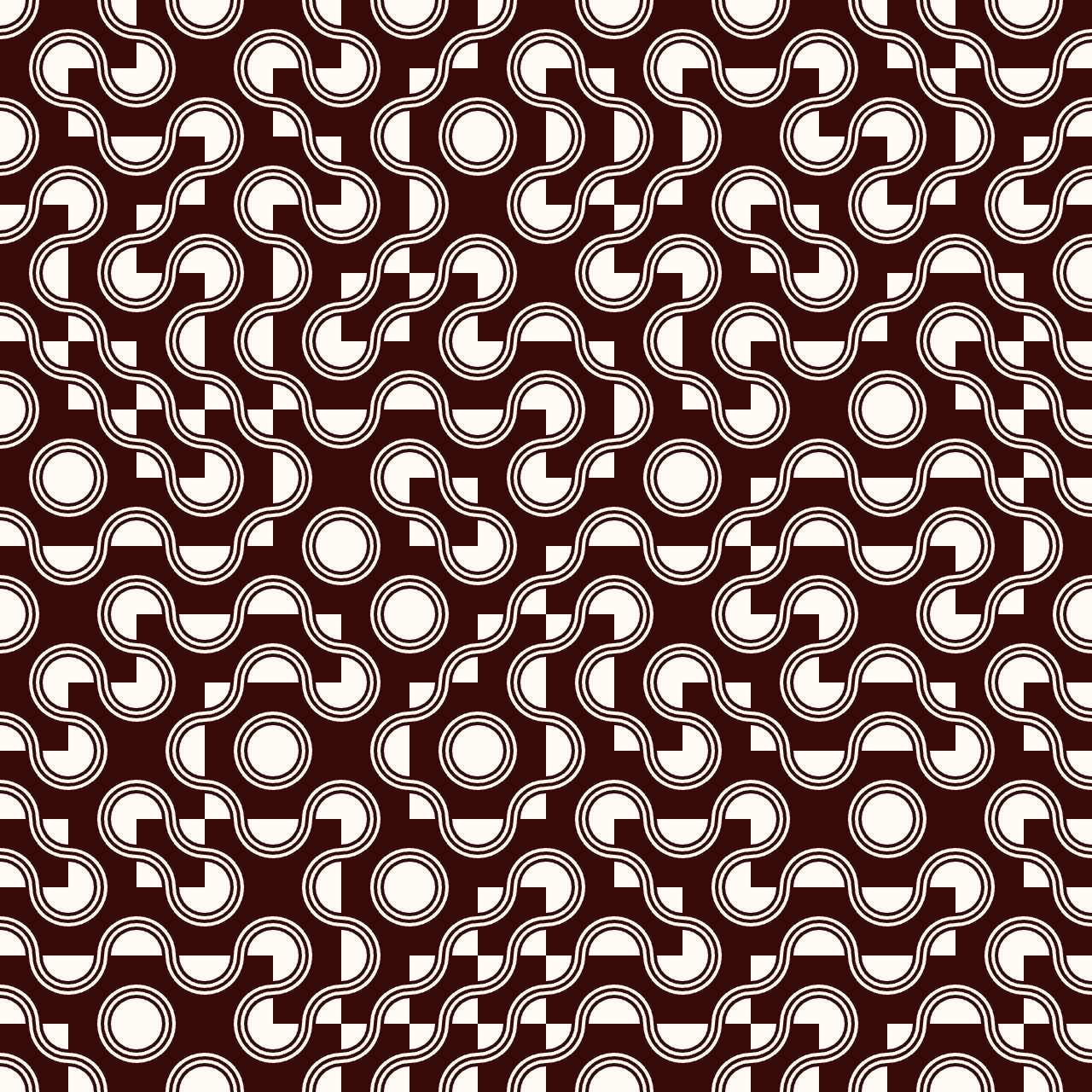
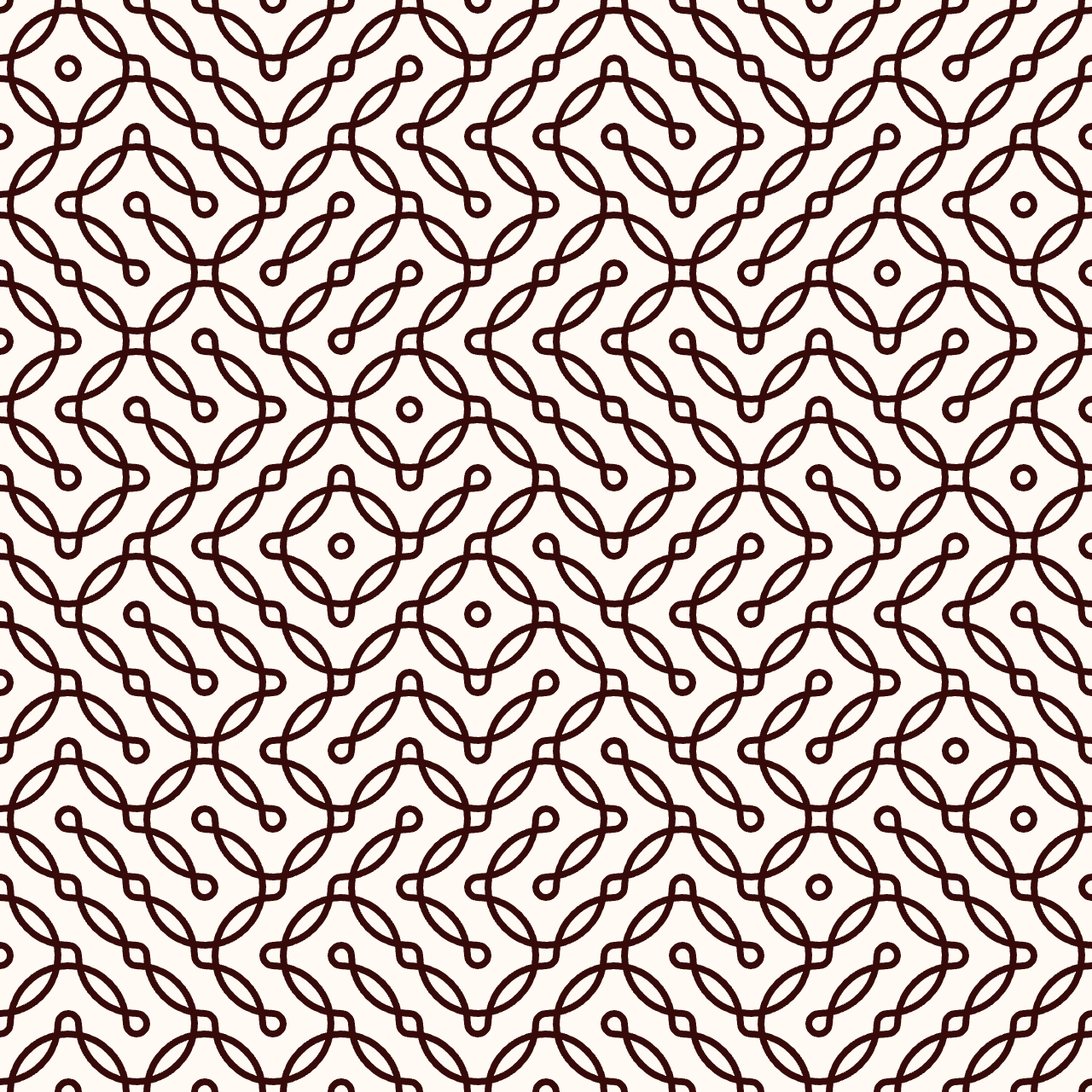
Finally some other plots with various values of a,b,c and stroke thickness:
Working with svg in p5.js
Using the p5.js-svg library
p5.js doesn't natively support svg format. Until now I was working with raster images and could export .png, although I knew in the end I would end up working with vector images in order to be able to machine the tiles with the waterjet machine. Indeed, I knew that was possible as a former colleague suceeded. So I went for tips online and here's what worked fine for me:
- I used is the library p5.js-svg
- Include the library by going in the
index.htmlfile of your p5.js project and adding the following line:<script src="https://unpkg.com/p5.js-svg@1.3.1"></script>. Note: to see all your project's content and access theindex.htmlfile, click on the < symbol as explained in the p5.js editor section. - In your
sketch.jsscript, add anSVGparameter when you create the canvas:createCanvas(windowHeight, windowHeight, SVG); - In order to save the vector graphics generated, add the instruction
save();in your sketch: your .svg graphic will be automatically downloaded - If you use the
save();instruction in a looping function such as thedraw();function which executes all the time, don't forget to add anoLoop();instruction. For example you can add the following condition in your thedraw()function sketch:
Well naturally you may face some difficulties adapting a raster image sketch to a vector one, as the library kind of limitates what you can do in p5.js and is less optimized. That was my case!
SVG truchet tiles
After successfully creating a simple sketch producing a vector image, I tried adapting my original truchet tile sketch. But that didn't work at all as expected! It seems it was a problem creating child canvas. I tried being using a more explicit algorithm without creating new canvas for each cell, but in the end got a bit lost on the way and decided to find another example method that could be more suitable for a svg adaptation.
I found an example on OpenProcessing. Here's the original animated sketch, submitted by Briag Dupont. I modified it to get rid of the animation, then added the SVG parameter in the createCanvas() function, and included the library in the index.html (as explained in the previous section).
//Truchet tiles in SVG
//Inspired from:
//https://openprocessing.org/sketch/505865/
//itself inspired by:
//Truchet tiles in 2D
//http://paulbourke.net/geometry/tilingplane/index.html#truchet
//SVG conversion thanks to: https://github.com/zenozeng/p5.js-svg
//Don't forget to add <script src="https://unpkg.com/p5.js-svg@1.3.1"></script> in your index.html.
//Directly save the generated svg and downloads it
//number of tiles in one side
var numTiles = 20;
var sizeTile;
var tiles = [];
function setup() {
createCanvas(windowHeight, windowHeight, SVG);
background(0);
sizeTile = width / numTiles;
colorMode(RGB, 255);
noFill();
for (var i = 0; i < numTiles; i++) {
for (var j = 0; j < numTiles; j++) {
tiles.push(new Tile);
tiles[j + i * numTiles].x = j * sizeTile + sizeTile / 2;
tiles[j + i * numTiles].y = i * sizeTile + sizeTile / 2;
tiles[j + i * numTiles].col = [2 * j, 0.8 * i];
}
}
}
function draw() {
background(255, 250, 244);
for (var i = 0; i < numTiles * numTiles; i++) {
tiles[i].display();
if (random() < 0.002) {
tiles[i].rotating = true;
}
}
   if (i > numTiles) {
        noLoop();
        save(); // comment if you don't want to save the generated svg
      }
}
//x,y: coordinates of the center of the tile, r:width of the tile
function Tile() {
this.x;
this.y;
this.r = sizeTile;
this.orientation = random();
this.rotation = 0;
this.rotating = false;
this.display = function() {
push();
translate(this.x, this.y);
noFill();
stroke(55, 10, 10);
strokeWeight(2);
if (this.orientation > 0.5) {
arc(-this.r / 2, -this.r / 2, this.r, this.r, 0, PI / 2);
arc(this.r / 2, this.r / 2, this.r, this.r, -PI, -PI / 2);
} else {
arc(-this.r / 2, this.r / 2, this.r, this.r, -PI / 2, 0);
arc(this.r / 2, -this.r / 2, this.r, this.r, PI / 2, PI);
}
pop();
}
}
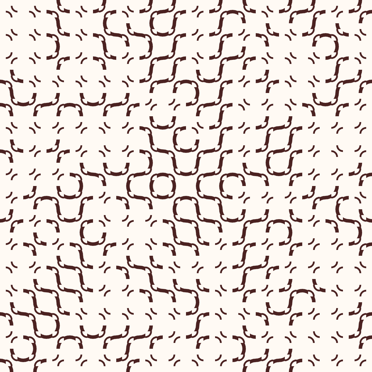
It worked just fine!

3 arcs svg truchet tiles
I then rewrote the sketch to have a similar result as in my previous explorations with circles of a, b and c diameters.
//Truchet tiles in SVG
//Inspired from:
//https://openprocessing.org/sketch/505865/
//itself inspired by:
//Truchet tiles in 2D
//http://paulbourke.net/geometry/tilingplane/index.html#truchet
//SVG conversion thanks to: https://github.com/zenozeng/p5.js-svg
//Don't forget to add  <script src="https://unpkg.com/p5.js-svg@1.3.1"></script> in your index.html.
//Directly save the generated svg and downloads it


//number of tiles in one side
var numTiles = 16;
var sizeTile;
var tiles = [];

const a=1;
const b=0.8;
const c=1.2;

function setup() {
    createCanvas(windowHeight, windowHeight, SVG);
    background(0);
    sizeTile = width / numTiles;
    colorMode(RGB, 255);
    noFill();
    for (var i = 0; i < numTiles; i++) {
        for (var j = 0; j < numTiles; j++) {
            tiles.push(new Tile);
            tiles[j + i * numTiles].x = j * sizeTile + sizeTile / 2;
            tiles[j + i * numTiles].y = i * sizeTile + sizeTile / 2;
            tiles[j + i * numTiles].col = [2 * j, 0.8 * i];
        }
    }
}

function draw() {
    background(255, 250, 244);
    for (var i = 0; i < numTiles * numTiles; i++) {
        tiles[i].display();
        if (random() < 0.002) {
            tiles[i].rotating = true;
        }
    }

      if (i > numTiles) {
        noLoop();
        //save(); // comment if you don't want to save the generated svg
      }
}

//x,y: coordinates of the center of the tile, r:width of the tile
function Tile() {
    this.x;
    this.y;
    this.r =  a*sizeTile;
    this.r2 = b*sizeTile;
    this.r3 = c*sizeTile;
    this.orientation = random();
    this.rotation = 0;
    this.rotating = false;
    this.display = function() {
    push();
    translate(this.x, this.y);
    noFill();
    stroke(55, 10, 10);
    strokeWeight(2);

        if (this.orientation > 0.5) {
            arc(-this.r / 2, -this.r / 2, this.r, this.r, 0, PI / 2);
            arc(this.r / 2, this.r / 2, this.r, this.r, -PI, -PI / 2);
            arc(-this.r / 2, -this.r / 2, this.r2, this.r2, 0, PI / 2);
            arc(this.r / 2, this.r / 2, this.r2, this.r2, -PI, -PI / 2);
            arc(-this.r / 2, -this.r / 2, this.r3, this.r3, 0, PI / 2);
            arc(this.r / 2, this.r / 2, this.r3, this.r3, -PI, -PI / 2);
        }

      else {
            arc(-this.r / 2, this.r / 2, this.r, this.r, -PI / 2, 0);
            arc(this.r / 2, -this.r / 2, this.r, this.r, PI / 2, PI);
            arc(-this.r / 2, this.r / 2, this.r2, this.r2, -PI / 2, 0);
            arc(this.r / 2, -this.r / 2, this.r2, this.r2, PI / 2, PI);
            arc(-this.r / 2, this.r / 2, this.r3, this.r3, -PI / 2, 0);
            arc(this.r / 2, -this.r / 2, this.r3, this.r3, PI / 2, PI);

        }
        pop();
    }
}
Machining the Truchet tiles
Unfortunately we didn't recieve our new abrasive sand stock on time, so I couldn't machine the truchet tiles before the global review.
Files
- Truchet tiles sketches
- Truchet tiles basic example (PNG):
- Truchet tiles 3 arcs (PNG):
- Truchet tiles SVG:
- Truchet tiles 3 arcs SVG:
- Waterjet tests files
- CAD files in .dxf:
- Star inlay Layout files
- Star inlay OMake files