Week 14 - Interfaces and application programming
Goals
- Individual assignment: write an application that interfaces a user with an input &/or output device that you made
- Group assignment: compare as many tool options as possible
Week's explorations and achievements
- I had no prior experience in interfacing arduino with processing
- I may have used Processing a dozen of years ago but not sure about that, so I am a beginner with Processing
- I had prior experience with C++ (the Processing language is apparently quite close to C++)
- I discovered how to interface arduino with processing by retrieving data with serial communication
- I discovered the analog flex sensor, which is really nice to make some interesting and fun interfaces
- I adapted examples to write real-time sketches producing sounds and visualization mapped on the analog values of the flex sensor (e.g depending on how the user bends it)
- I played around with the sound library to use two flex sensors at the same time, mapped on slightly different sound functions.
Group assignment
This week's group assignment was about comparing tools and options for interfaces and applications programming.
Though we didn't really had the time to explore several tools, we had a discussion about other options, in particular interfacing our microcontroller with web browsers. I explored a bit further this question thanks to a very rich tutorial, as I am quite interested by P5.js. It's better to read the group assignment after the individual assignment as it refers to what I've learned during the individual assignment.
Interfacing Arduino with Processing
Steps to follow
Processing is a flexible software allowing to write sketches for a variety of applications such as visualization and graphics art, used by a lot of artists working on interactivity. It is particularly convenient to use in parallel with arduino sketches. An easy way to do so is to retrieve data from the serial monitor. I downloaded the latest version of Processing, which is currently Processing 4.
The process is thus the following if you want to retrieve data from arduino inputs (for example sensors):
- Make an electronic circuit with a programmable board with sensors connected to GPIO (analog GPIOs if you're using analog sensors)
- In Arduino, write a sketch to retrieve the analog values measured by the sensors, with the
analogRead()function. Optionnaly you can map these values to a more meaningful interval withmap(). - In this sketch, initialize a serial communication with
Serial.begin(9600);(or another rate) and retrieve the analog values and print them in the serial monitor withSerial.println(), for exampleSerial.println(angle);. The use ofSerial.println()compared toSerial.print()will be useful to read each line separately in the Processing sketch (asSerial.println()creates a new line). - Connect this board in USB to a computer. Programm the board and make sure the values measured by the sensors are printed in the serial monitor. If you're using a self-made board with an ATtiny, make sure you use an FTDI converter to be able to initiate the serial communication through the USB cable.
- Write a new sketch in Processing. Include the serial library with the command line
import processing.serial.*;and create a new object withSerial myPort; - In the setup fonction in the Processing sketch, initiate a serial communication at the same rate as in the arduino sketch and indicating which serial port you're reading. You'll probably need to change the portName
Serial.list()[]to another number to find the adequate serial port. To make sure you use the right one, you'll need to observe in the processing serial monitor that you print correctly the sensore values (see in the next steps).
  String portName = Serial.list()[0]; //change the 0 to a 1 or 2 etc. to match your port
  myPort = new Serial(this, portName, 9600);
- In the
draw()function in the Processing sketch, listen to values coming from the serial port and store them in a new value. The commandmyPort.readStringUntil('\n');allows to read one line in the serial port at a time.
  if ( myPort.available() > 0)
  {  // If data is available,
    val = myPort.readStringUntil('\n');         // read it and store it in val
    try {
         sensorVal = Float.valueOf(val.trim());
         }
    catch(Exception e) {
          ;
         }
  }
-
In the processing sketch, print the retrieved values in its serial monitor to make sure you're correctly reading the values from the serial port, with the function
println(), for exampleprintln(sensorVal);. If it only displays0.0ornullit's probably because you have to change the portName to another value inSerial.list()[0]. Change the number0for 1, 2, 3 etc., until you can read the values. If you get an error message saying the serial port is busy it's surely because you kept it open in the Arduino sketch. In this case just close the serial monitor in arduino. -
You're now ready to use the values in your processing sketch, for visualization or any kind of interactivity! Again, you can optionnaly map the values to a more convenient interval with the
map()function. For examplefloat amplitude = map(sensorVal, -20, 150, 1.0, 0.0);
Retrieving several values
When I used two sensors at the same time I faced the situation of needing to retrieve several values in the serial port. Should you add delay to make a difference between the two variables? I finally found a very convenient and satisfying solution. The general idea is the following:
- Let's say you have two sensors on your circuits and you read them in Arduino with
analogRead(PIN_A);andanalogRead(PIN_B);, and store them in two variables:sensorVal_a = analogRead(PIN_A);andsensorVal_b = analogRead(PIN_B); - You'll print them in the serial monitor on the same line but making sure you separate the values with a distinctive symbol, for exampe with ",". Your command will look like:
- Then in the processing sketch you'll have to apply the
split()function to the string read in the serial port (each line at a time), then store in an String array the splitted values, using indexes. Here I first read each line in the serial port withval = myPort.readStringUntil('\n');then split this string and store them in a new arrayString[]:String[] values = split(val, ',');. Finally I can refer to the two values independently by setting two floats to the float values of each string of the array, withsensorVal_a = Float.valueOf(values[0].trim());andsensorVal_b = Float.valueOf(values[1].trim());, 0 and 1 being the indexes in the String array. Putting this all together we have:
  if ( myPort.available() > 0)
  {
    val = myPort.readStringUntil('\n');
    String[] values = split(val, ',');
    try {
         sensorVal_a = Float.valueOf(values[0].trim());
         sensorVal_b = Float.valueOf(values[1].trim());
         }
    catch(Exception e) {
          ;
         }

  }
- This method of course applies to more than one value. You'd only have to print them on arduino's serial monitor on the same line, separated by
",", then split themString[] values = split(val, ',');and store them reffering to the indexes (values[0],values[1],values[2], etc).
You can find full code examples of what I experimented this week later on this page.
First tests
Making sure I can retrieve serial data
Arduino sketch:
//Arduino
void setup() {
  Serial.begin(9600);


}

void loop() {
  Serial.println("Let's count");
  delay(500);
}
Processing sketch:
//Processing
import processing.serial.*;

Serial myPort;  // Create object from Serial class
String val;     // Data received from the serial port

void setup()
{
  // I know that the first port in the serial list on my mac
  // is Serial.list()[0].
  // On Windows machines, this generally opens COM1.
  // Open whatever port is the one you're using.
  String portName = Serial.list()[1]; //change the 0 to a 1 or 2 etc. to match your port
  myPort = new Serial(this, portName, 9600);
}

void draw()
{
  if ( myPort.available() > 0)
  {  // If data is available,
  val = myPort.readStringUntil('\n');         // read it and store it in val
  }
println(val); //print it out in the console
}
Counting integers
Arduino sketch:
//Arduino

void setup() {
  Serial.begin(9600);
  Serial.println("Let's count");

}

void loop() {

  for (int i=1; i<=100; i++){
    Serial.println(i);
    delay(500);
  }

}
Processing sketch:
//Processing
import processing.serial.*;

Serial myPort;  // Create object from Serial class
String val;     // Data received from the serial port
int countVal = 0;

void setup()
{

  String portName = Serial.list()[1]; //change the 0 to a 1 or 2 etc. to match your port
  myPort = new Serial(this, portName, 9600);
}

void draw()
{
  if ( myPort.available() > 0)
  {  // If data is available,
    val = myPort.readStringUntil('\n');         // read it and store it in val
    try {
         countVal = Integer.valueOf(val.trim());
         }
    catch(Exception e) {
          ;
         }

  }
println(countVal); //print it out in the console
delay(500);
}
I then tried working with a heart pulse sensor but couldn't find a satisfying level to detect the heartbeats.
Flex sensors experimentations
How do they work?
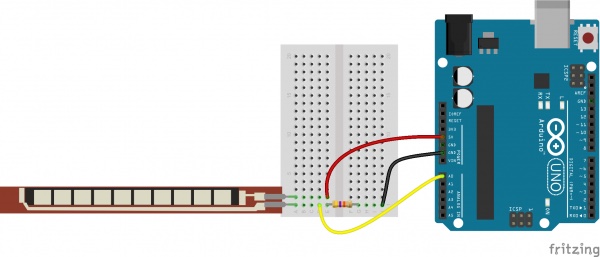
This was my first time working with flex sensors. We had them in the lab and I thought they would be funny to work with to have an interesting and playful human-machine interface. These small flexible circuits contain conductive ink. When bent, this results in a resistor variation. By combining the flex sensor with a static resistor to create a voltage divider, you can produce a variable voltage that can be read by a microcontroller's analog-to-digital converter.
I used this useful tutorial on Sparkfun to learn how to use them. I created a small circuit on a breadboard with 47kOhm resistors.
First test on an Uno
I used the example on sparkfun.
I first tested one flex sensor with an arduino Uno
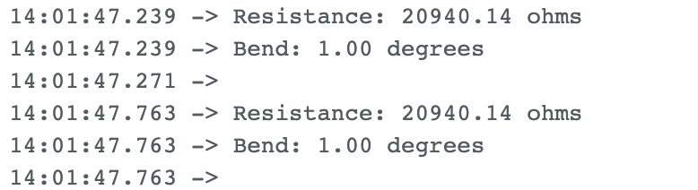
It is easier to map the values retrieved with the analogWrite on angles. To do so you measure the resistance of the flex sensor in two cases, for example not bent and bent to approximatively 90°. I did the measure in the serial port.
Here's where you should put the results of the measures:
const float STRAIGHT_RESISTANCE = 20747; // resistance when straight
const float BEND_RESISTANCE = 36280.0; // resistance at 90 deg
Arduino sketch, adapted from the Sparkun's example.
/******************************************************************************
Flex_Sensor_Example.ino
Example sketch for SparkFun's flex sensors
(https://www.sparkfun.com/products/10264)
Jim Lindblom @ SparkFun Electronics
April 28, 2016
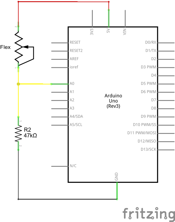
Create a voltage divider circuit combining a flex sensor with a 47k resistor.
- The resistor should connect from A0 to GND.
- The flex sensor should connect from A0 to 3.3V
As the resistance of the flex sensor increases (meaning it's being bent), the
voltage at A0 should decrease.
Development environment specifics:
Arduino 1.6.7
******************************************************************************/
const int FLEX_PIN = 5; // Pin connected to voltage divider output //AO on arduino UNO, PB4 = GPIO6 = 5 on my attiny3216 devboard
// Measure the voltage at 5V and the actual resistance of your
// 47k resistor, and enter them below:
const float VCC = 4.98;
const float R_DIV = 47500.0;
// Upload the code, then try to adjust these values to more
// accurately calculate bend degree.
const float STRAIGHT_RESISTANCE = 20747; // resistance when straight
const float BEND_RESISTANCE = 36280.0; // resistance at 90 deg
void setup()
{
Serial.begin(9600);
pinMode(FLEX_PIN, INPUT);
}
void loop()
{
// Read the ADC, and calculate voltage and resistance from it
int flexADC = analogRead(FLEX_PIN);
//Serial.println(flexADC);
float flexV = flexADC * VCC / 1023.0;
float flexR = R_DIV * (VCC / flexV - 1.0);
//Serial.println("Resistance: " + String(flexR) + " ohms");
// Use the calculated resistance to estimate the sensor's
// bend angle:
float angle = map(flexR, STRAIGHT_RESISTANCE, BEND_RESISTANCE,
0, 90.0);
//Serial.println("Bend: " + String(angle) + " degrees");
Serial.println(angle);
delay(100);
//Serial.println();
}
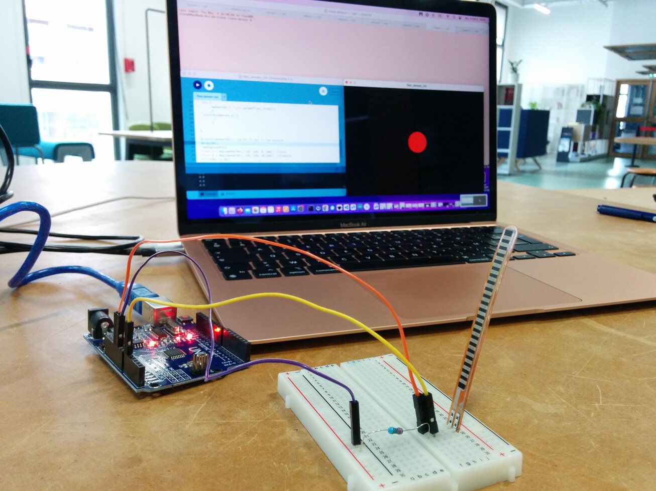
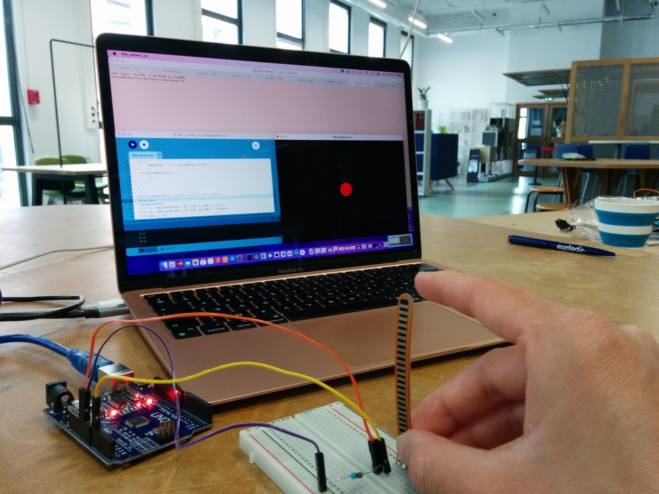
In Processing, I first only visualized the evolution of the angle, then used the sound library to map these values on amplitude, frequency and panning of a sine wave.
Hopefully I will be able to get back the videos I recorded.
Two flex sensors
I then tested with two flex sensors, first on an arduino Uno then on my board (I had analog inputs on my GPIOs 5 and 6, corresponding to arduino pins 4 and 5).
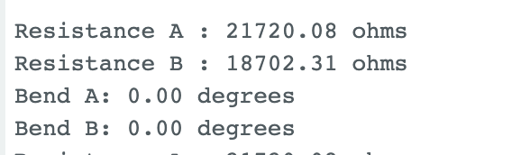
I also measured the resistors values to map each sensor values.
The main difficulty was to retrieve several datas from the serial port. I explained how I proceeded at the beginning of this page, in section Retrieving several values.
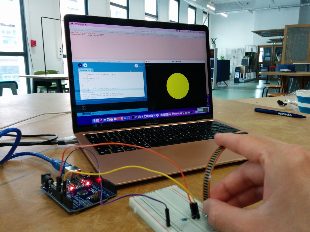
In a first sketch, the two flex sensors monitor the same sine: angle_a monitors amplitude and angle_b the frequency (see code below, version 2)
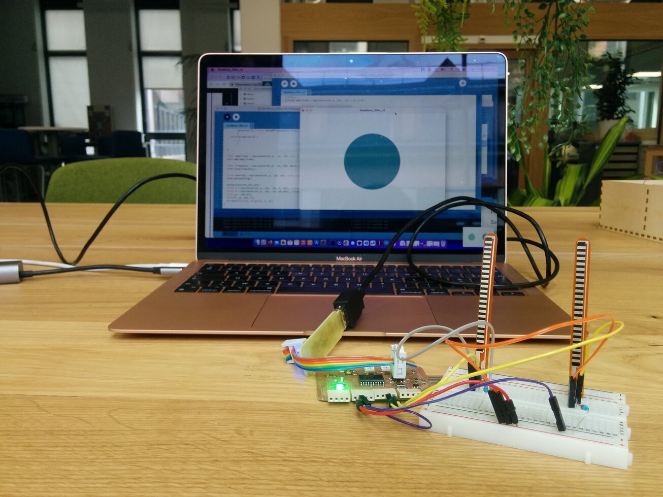
These values also influences the colors and transparency. From the very first sine example with one flex sensor I also changed the visualization for something that felt more logical to me: brighter and acid colors for higher frequencies, and also smaller disc - the sound seems more dense and pointy to me.
I then wrote another sketch where the two flex sensors control differents sine waves (see code below version3). I played with the frequency ranges until I obtained something I liked to play.
I kept working with a breadboard for a while since it seems the flex sensors are sensititive to soldering (the heat can damage the conductive ink).
But ultimately I finally decided to make a small circuit using the Graphtec Pro 9000 vinyl cutter (see below).
Code
Arduino sketch:
/******************************************************************************
Inspired by the example Flex_Sensor_Example.ino
Example sketch for SparkFun's flex sensors
  (https://www.sparkfun.com/products/10264)
Jim Lindblom @ SparkFun Electronics
April 28, 2016
******************************************************************************/
const int FLEX_PIN_A = 5; // Pin connected to voltage divider output //AO on arduino UNO, PB4 = GPIO6 = 5 on my attiny3216 devboard
const int FLEX_PIN_B = 4;

// Measure the voltage at 5V and the actual resistance of your
// 47k resistor, and enter them below:
const float VCC = 4.98; // Measured voltage of Ardunio 5V line
const float R_DIV = 47500.0; // Measured resistance of 3.3k resistor

// Upload the code, then try to adjust these values to more
// accurately calculate bend degree.
const float STRAIGHT_RESISTANCE_A = 21720; // resistance when straight //37300 //20747
const float BEND_RESISTANCE_A = 41000; // resistance at 90 deg //36280

const float STRAIGHT_RESISTANCE_B = 18792; // resistance when straight //37300 //20747
const float BEND_RESISTANCE_B = 36861.0; // resistance at 90 deg //36280

void setup()
{
  Serial.begin(9600);
  pinMode(FLEX_PIN_A, INPUT);
  pinMode(FLEX_PIN_B, INPUT);
}

void loop()
{

  int flexADC_A = analogRead(FLEX_PIN_A);
  float flexV_A = flexADC_A * VCC / 1023.0;
  float flexR_A = R_DIV * (VCC / flexV_A - 1.0);

  int flexADC_B = analogRead(FLEX_PIN_B);
  float flexV_B = flexADC_B * VCC / 1023.0;
  float flexR_B = R_DIV * (VCC / flexV_B - 1.0);
  float angle_A = map(flexR_A, STRAIGHT_RESISTANCE_A, BEND_RESISTANCE_A,
                   0, 90.0);

  float angle_B = map(flexR_B, STRAIGHT_RESISTANCE_B, BEND_RESISTANCE_B,
                   0, 90.0);
  Serial.print(angle_A);
  Serial.print(",");
  Serial.println(angle_B);
  delay(100);

}
Processing sketch version 2: one of the flex sensor monitors amplitude and the other one monitors frequency
/**
 * This is a sine wave oscillator. The method .play() starts the oscillator. There
 * are several setter functions for configuring the oscillator, such as .amp(),
 * .freq(), .pan() and .add(). If you want to set all of them at the same time you can
 * use .set(float freq, float amp, float add, float pan)
 */

import processing.sound.*;
import processing.serial.*;

Serial myPort;  // Create object from Serial class
String val;     // Data received from the serial port
float sensorVal_a = 0;
float sensorVal_b = 0;

SinOsc sine;

void setup() {

  String portName = Serial.list()[1]; //change the 0 to a 1 or 2 etc. to match your port
  myPort = new Serial(this, portName, 9600);


  background(255);
  size(720, 480);
  noStroke();
  noFill();

  // create and start the sine oscillator.
  sine = new SinOsc(this);
  sine.play();
}

void draw() {

  if ( myPort.available() > 0)
  {  // If data is available,
    val = myPort.readStringUntil('\n');        // read it and store it in val
    String[] values = split(val, ',');
    try {
         sensorVal_a = Float.valueOf(values[0].trim());
         sensorVal_b = Float.valueOf(values[1].trim());
         }
    catch(Exception e) {
          ;
         }

  }

  float amplitude = map(sensorVal_a, -20, 150, 1.0, 0.0);
  sine.amp(amplitude);

  float frequency = map(sensorVal_b, -20, 150, 80.0, 1000.0);
  sine.freq(frequency);

  float panning = map(sensorVal_a, -20, 150, -1.0, 1.0);
  sine.pan(panning);

  background(255,255,255);
  float t = map(sensorVal_a, 150, -20, 0, 255); //transparency
  float d = map(sensorVal_b, 150, -20, 40,350); //diameter
  float g = 240-d/3;
  fill(77, g, 158, t);
  ellipse(width/2, height/2, d, d);
}
Processing sketch version 3: each flex sensors control a different sine (different frequency range).
/**
 * This is a sine wave oscillator. The method .play() starts the oscillator. There
 * are several setter functions for configuring the oscillator, such as .amp(),
 * .freq(), .pan() and .add(). If you want to set all of them at the same time you can
 * use .set(float freq, float amp, float add, float pan)
 */

import processing.sound.*;
import processing.serial.*;

Serial myPort;  // Create object from Serial class
String val;     // Data received from the serial port
float sensorVal_a = 0;
float sensorVal_b = 0;

SinOsc sine;
SinOsc sine_b;


void setup() {

  String portName = Serial.list()[1]; //change the 0 to a 1 or 2 etc. to match your port
  myPort = new Serial(this, portName, 9600);


  background(255);
  size(720, 480);
  noStroke();
  noFill();

  // create and start the sine oscillator.
  sine = new SinOsc(this);
  sine.play();

  sine_b = new SinOsc(this);
  sine_b.play();
}

void draw() {

  if ( myPort.available() > 0)
  {  // If data is available,
    val = myPort.readStringUntil('\n');        // read it and store it in val
    String[] values = split(val, ',');
    try {
         sensorVal_a = Float.valueOf(values[0].trim());
         sensorVal_b = Float.valueOf(values[1].trim());
         }
    catch(Exception e) {
          ;
         }

  }

  //sine_a
  //float amplitude = map(sensorVal_a, 150, -20, 1.0, 0.0);

  float amplitude;


    if (sensorVal_a <= 30){
    amplitude = sensorVal_a/100 - 0.1;
  }

  else{
    amplitude = 0.8;
  }


  sine.amp(amplitude);

  float frequency = map(sensorVal_a, -20, 150, 80, 320.0);
  sine.freq(frequency);

  float panning = map(sensorVal_a, -20, 150, -1.0, 1.0);
  sine.pan(panning);

  //sine_b

  //float amplitude_b = map(sensorVal_b, 150, -10, 1.0, 0.0);
  float amplitude_b;

  if (sensorVal_b <= 20){
    amplitude_b = sensorVal_b/100 - 0.1;
  }

  else{
    amplitude_b = 0.8;
  }

  sine_b.amp(amplitude_b);

  float frequency_b = map(sensorVal_b, -10, 150, 160.0, 480.0);
  sine_b.freq(frequency_b);

  float panning_b = map(sensorVal_b, -20, 150, -1.0, 1.0);
  sine_b.pan(panning_b);


  background(255,255,255);
  float t = map(sensorVal_a, 150, -20, 0, 255); //transparency
  float d = map(sensorVal_a, 150, -20, 40,200); //diameter
  float g = 240-d/3;
  //fill(77, g, 158, 255-t);
  fill(77, g, 158, 255);
  ellipse(3*width/4, height/2, d, d);

  float t_b = map(sensorVal_b, 150, -20, 0, 255); //transparency
  //fill(27, g, 198, 255-t_b);
  float d_b = map(sensorVal_b, 150, -20, 40,200); //diameter
  float b_b = 240-d_b/2;
   fill(27, 120, b_b, 255);
  ellipse(width/4, height/2, d_b, d_b);
}
Circuit board
Still struggling having access to the pictures I took during the process :/
I decided to do a small simple board that would work as a module for my flex sensors. I tried for the first time making this board with the vinyl cutter, conductive tape and a plasti sheet of PETG. I used 0.75mm thick PETG we had for the vacuum forming. I used light settings to cut the tape. Went fine for a first circuit but be careful with the solder iron, it melts the plastic!
Kicad design
I draw the components for the flex sensors. I put 2 VCC headers because it was easier to route that way.
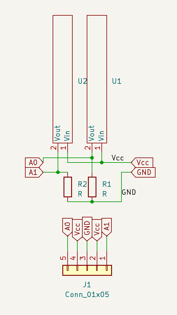
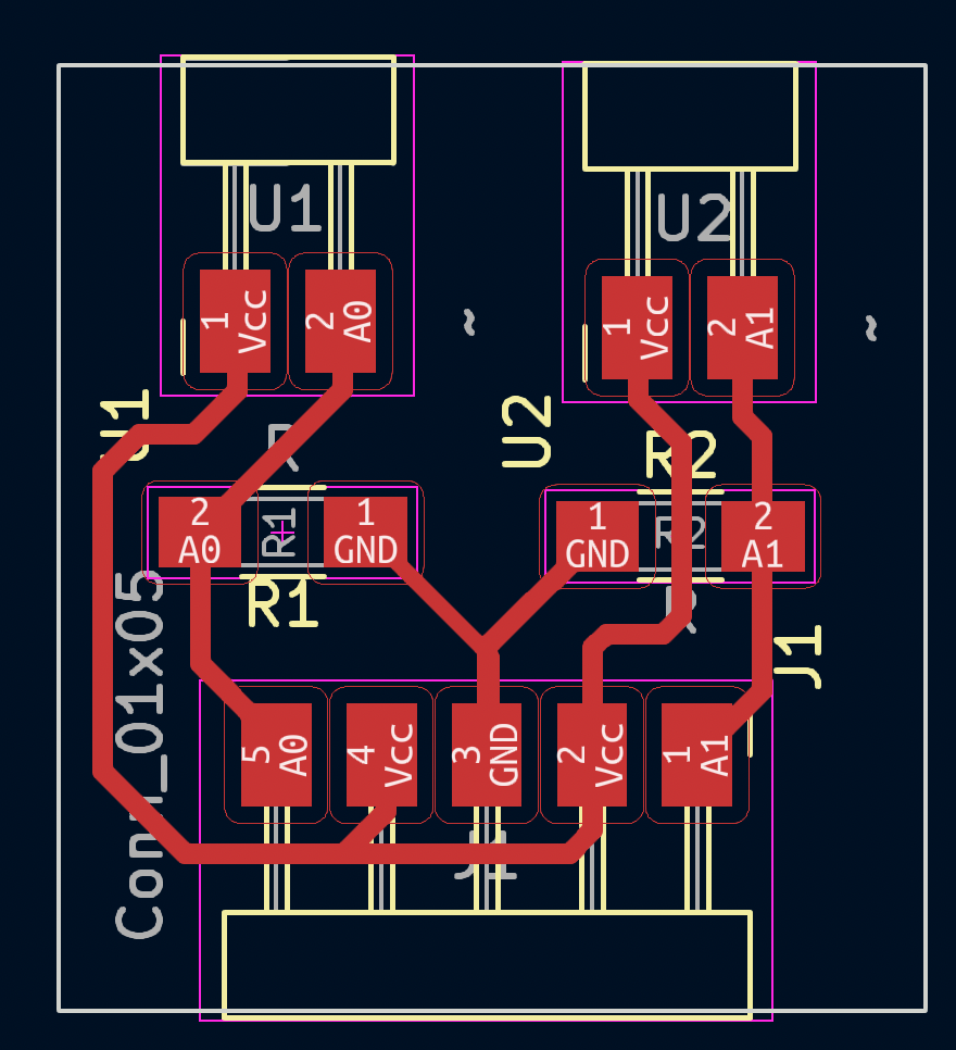
For the flex sensors footprints I used the same footprints as for the horizontal pin headers 2.54mm. I used 1206 footprints for the 47kOhms resistors, as usual.
I traced 0.5mm width routes, with a 0.4mm tolerance. The outline is not really important here.
Vinyl cutting
Unfortunately I cannot retrieve the pictures I took (battery problem on my cellphone), but here's the process:
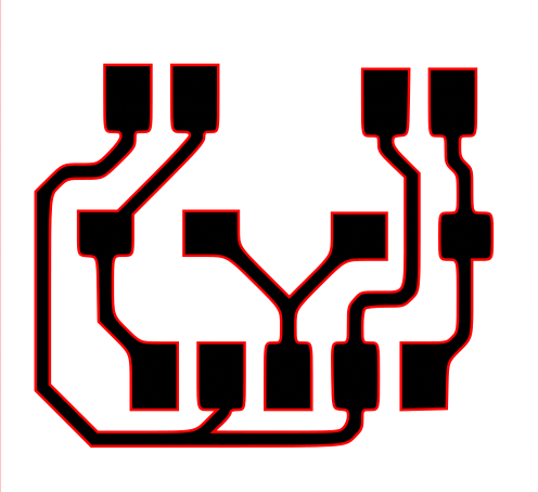
- I exported the F.CU as .svg
- Not really the cleanest way to do so, but I opened it in Inkscape and exported it as a png
- ... and vectored it afterwards!
- I traced the outline in red and saved it as a .dxf
- I downloaded and opened Graphtec Studio on this page for Mac.
- I imported the dxf and did a test on the Graphtec pro 9000 vinyl cutting machine on a regular piece of sticker. I didn't identify issues here so I moved forward.
- I applied a piece of conductive tape on a 0.75mm thick PETG transparent sheet
- I loaded it in the vinyl cutting machine, placed correctly the wheels, then selected charger la feuille. The machine measures automatically the maximal petg sheet dimensions
- I moved the cutter head above the conductive tape piece and selected Origine to set the new origin.
- I changed the settings for slower and lighter one than for a regular piece of vinyl.
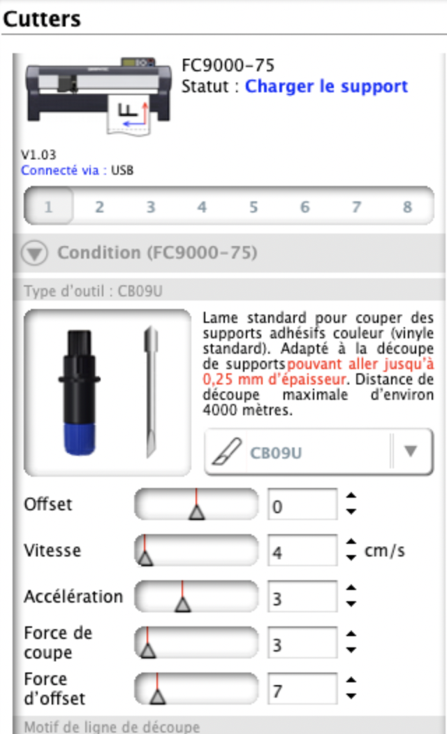
- I launched the job and it went fine from this first attempt.
- The conductive tape sticks a lot to the petg, I had to use an exacto knife to remove all the unwanted copper tape.
Soldering and testing
I was a bit afraid of soldering the flex sensors, which are supposedly very sensitive to heat due to the conductive ink. Otherwise all went fine expect I held the soldering iron close to my circuit for a bit too long in some places, making the petg sheet to melt a little bit. So the result is not super clean but it works as expected.
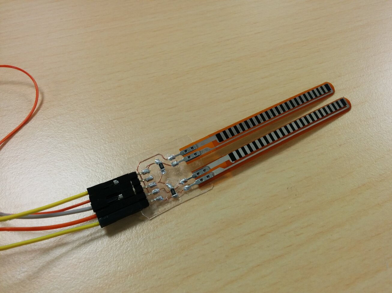
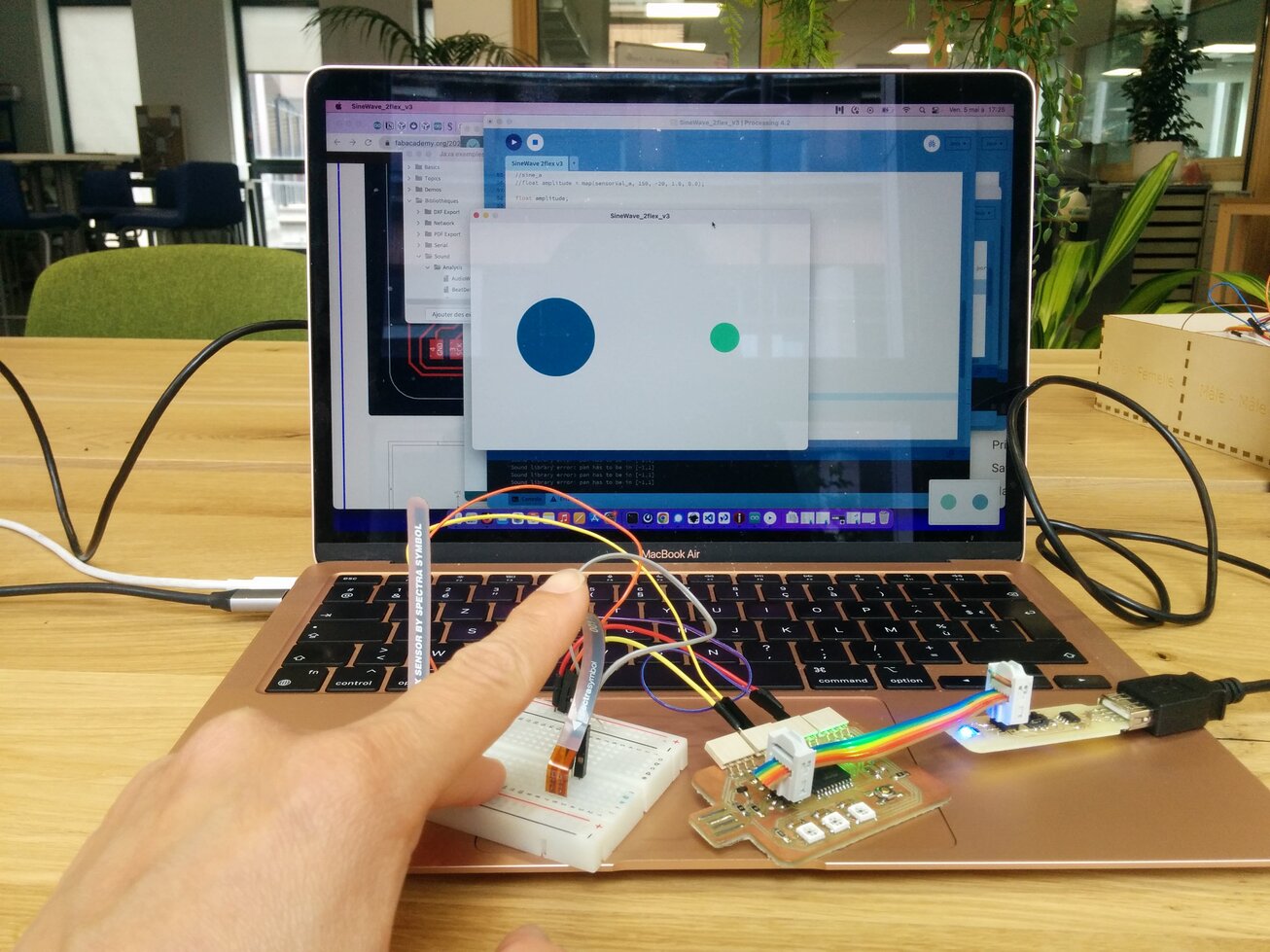
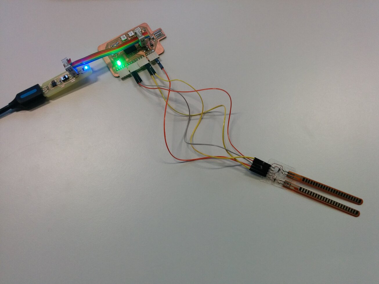
I used the newly designed and produced updi / ftdi programmer of my colleague and instructor Stéphane to upload my sketch, then used USB for serial communication. Jumpers: orange: Vcc /3.3V, grey: ground, yellow: analog GPIO5 (arduino 4) and GPIO6 (arduino(5).
Unfortunately I'm struggling with adding the videos right now.
Files
Arduino sketch for 2 flex sensors
Processing sketch 2 flex sensors version 2