dummy
9. OUTPUT DEVICES
This week, it is more about programming and testing our PCB’s. And I have worked a bit more in the Final Project concept with the information I have gathered until now.
HERO IMAGE
ASSIGNMENTS
Gropup Assignment
- Measure the power consumption of an output device.
- Document my work on the group work page and reflect on my page what I learned.
Individual Assignment
- Add an output device to a microcontroller board I've designed and program it to do something.
GROUP ASSIGNMENT
It was very challenging for us to do the coding to control the Outputs and make them do what we wanted, we sticked to simple codes and tweaked them a little bit. When we measured the power consuption of them we could conclude that the speed of the operation, in this case Servo motors, could increase the Power consuption.
This is a very important conclusion for me as my "final project" is based in Servo Motors and they will be battery powered, it means that I have to be careful with the speeds in which I actuate the Servos to save energy consuption.
-Two Servo Motors Sweep Mode
We modified the code so that the servos move at different directions. We try to change to different speed for each servo but we needed more time to figure it out. We observed similar current surged when there is change of direction and speed.
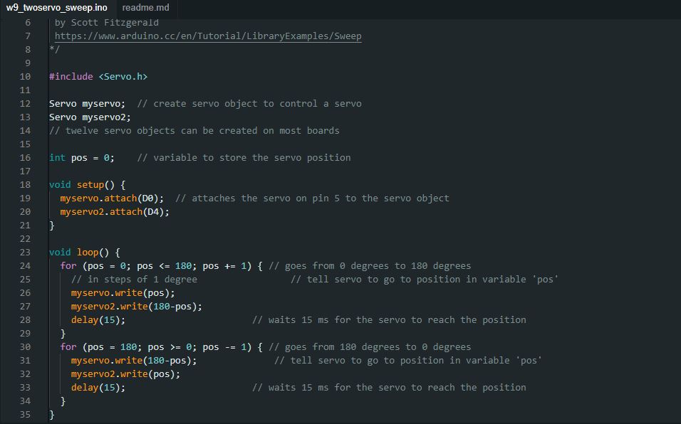
With this code, the movement of the shaft was more controlled with a lower average of 0.07 amperes, and a higher amperage 0.33. The higher amperage was the result of the servo motor arm movement, when it went pretty fast from the angle of 180 to 0 degrees to start the loop again
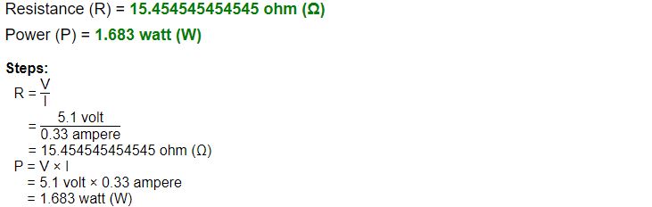
We had for the avergare high 0.7 amperes with a constant voltage of 5.1 we then:

The values for the avergare high of 0.33 amperes with a constant voltage of 5.1 we have:
You can see HERE more about the group assigment, where we see more in detail the CNC machine operation
INDIVIDUAL ASSIGNMENT
As my final project will have several servos to move different modules at different angles, I decided to start controlling one servo motor with my XIAO RP2040 PCB, then add another Servo and lastly I wanted to include the Blink Code together with moving the servo, just to see how to merge two codes.
-Servo Motors
I found THIS WEB PAGE, pretty helpful to guide me with the concepts and the programming of servo motors.
The servo motors can move on an Axis 180 degrees, and there are several types, but the main difference between them is the precision of their movement. The sensor to control the position in the most simple servos is a potentiometer. These types of servos are called, Hobby servos and they are cheap, making them pretty useful for prototyping. I will be working with them.
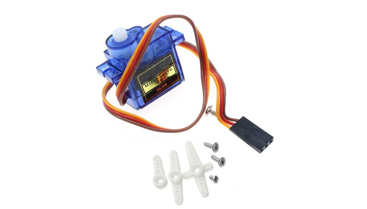
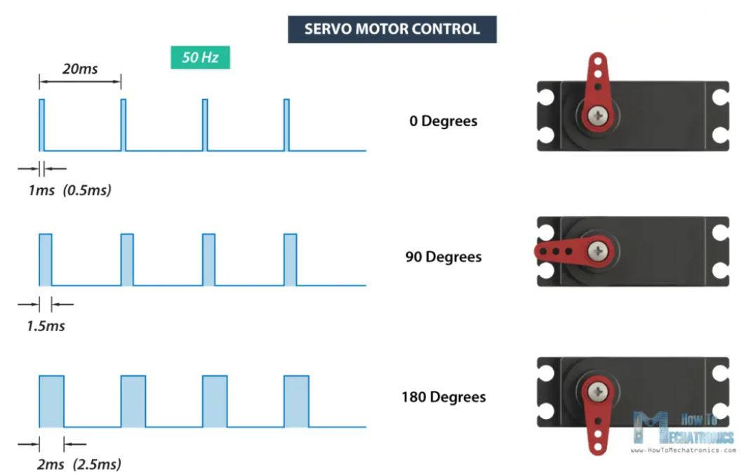
A servo motor is controlled by sending a series of pulses through the signal line. The frequency of the control signal should be 50Hz or a pulse should occur every 20ms. The width of the pulse determines the angular position of the servo and these types of servos can usually rotate 180 degrees (they have a physical limit of travel).
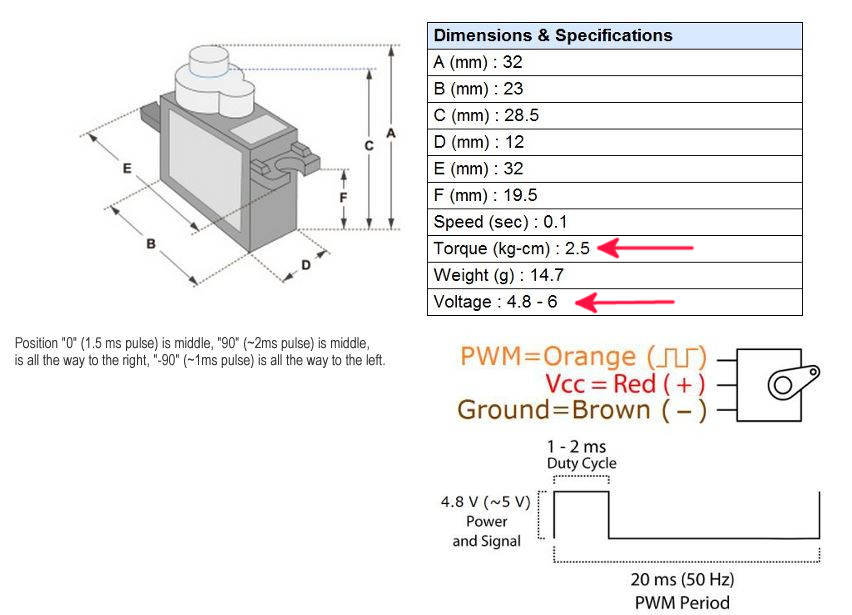
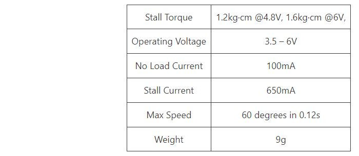
In the specs of the servo, I am using, an SG90. we can see the Torque is not really high, so I have to consider this for the final project design. The operating voltage is 4.8 ~ 6V, and as I have enabled 5V pins in my PCB I can connect directly to it.
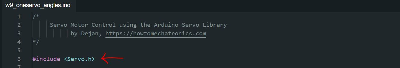
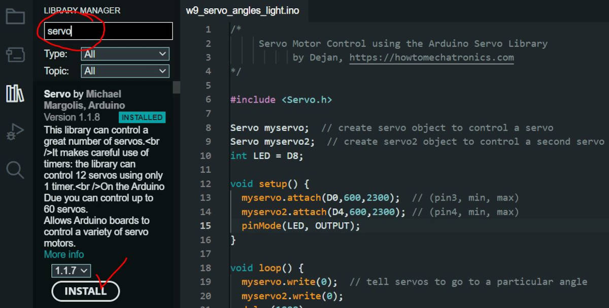
To control the motor, I used the Arduino Servo Library, which can be found in: Sketch>include Libraries>manage libraries.
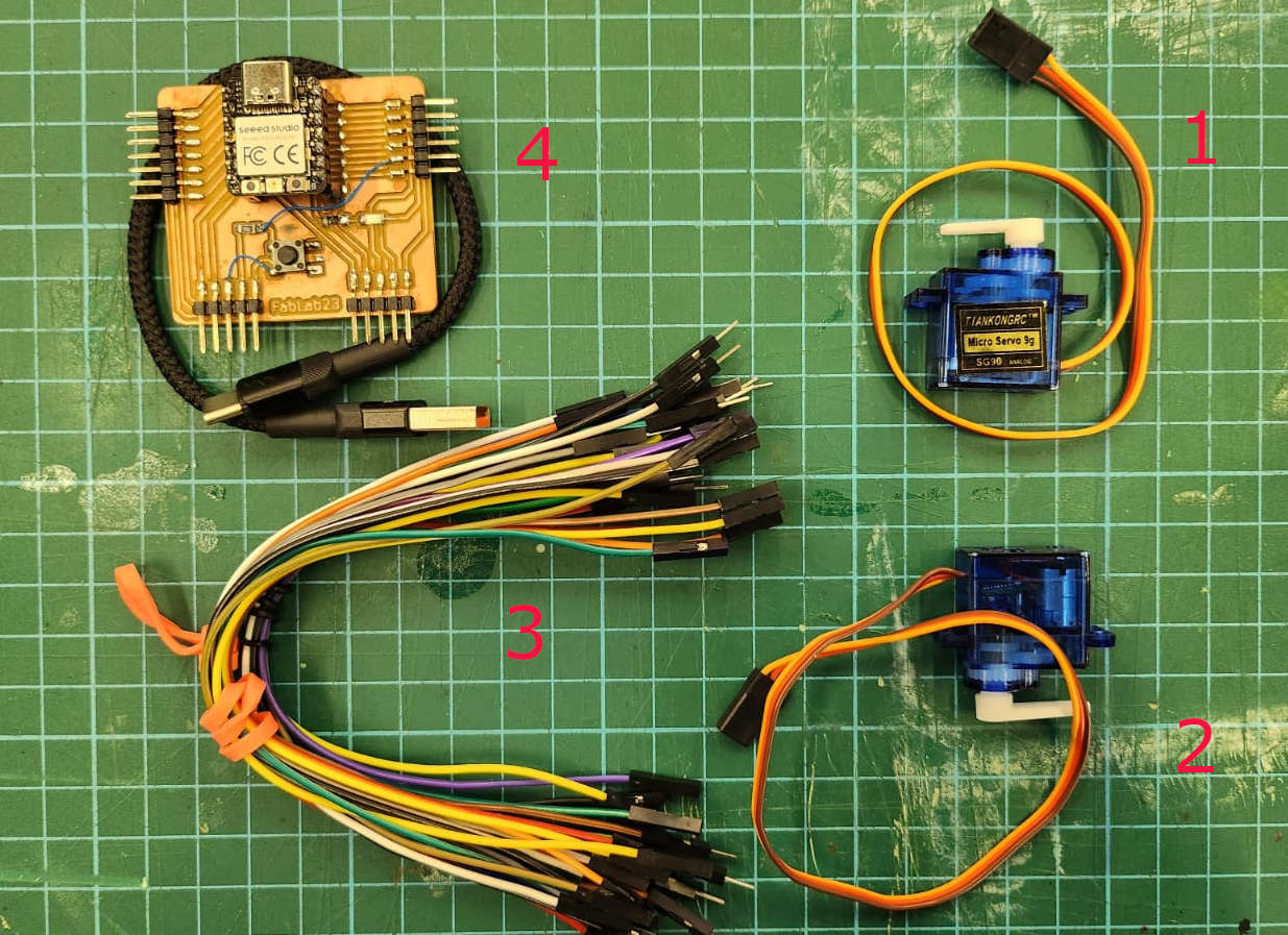
For the connection of the Servo motors I needed:
- Servo Motor 1
- Servo Motor 2
- Jumper wires
- PCB XIAO RP2040 with USB cable
- Breadboard
- DC Bench Power supply
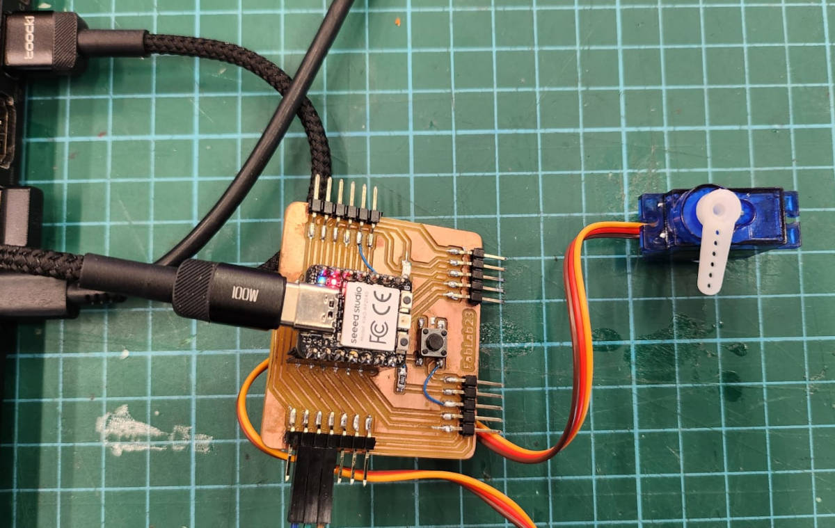
For this Assignemet I used the PCB board I have produced in the Week 6.Electronic design.
In principle one or two Servo Motors can be connected to the PCB directly with the Pins of 5V, GND and Data, but to measure the use of the power consumption we hooked up the motors to the DC Power supply through the Bread board, just leaving the data connected to the PCB board but the GND and 5V connected to the Bench.
I left the PCB board power supply connected to the Bench too though 5V and GND to the Breadboard
-Programming
-One servo moving in programmed angles
The first code is to make one Servo Motor to move in four different angles, 0, 90, 135 and 180 (find the code down below in Links to the working files)
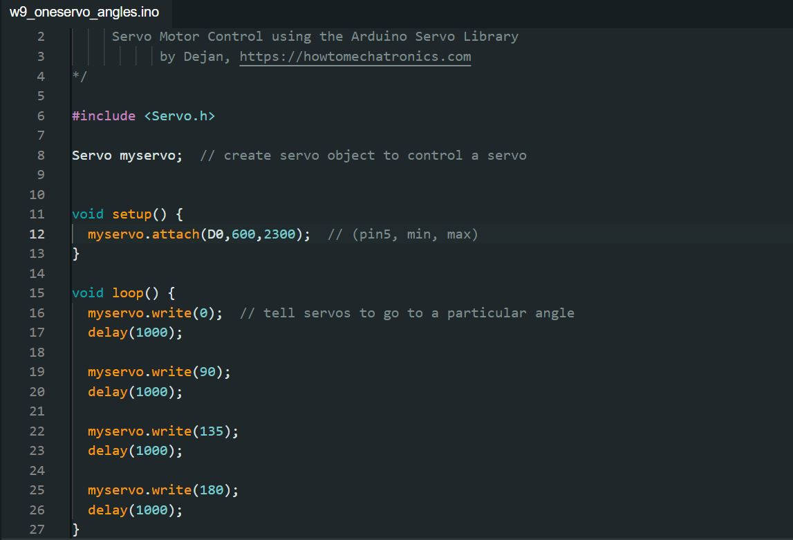
I could measure with the bench Power supply that given a continuous power supply of 5.1V the current that the servo was using for this code was variable, for the second and third change of angle, the current consumption was around 4.A but for the first angle and coming back from 180 to 0 position the consumption went up to around 17.A
Then I put two servos with the same code to move in angles and add the code of the blinking light. (for the code find it down below in Links to the working files)
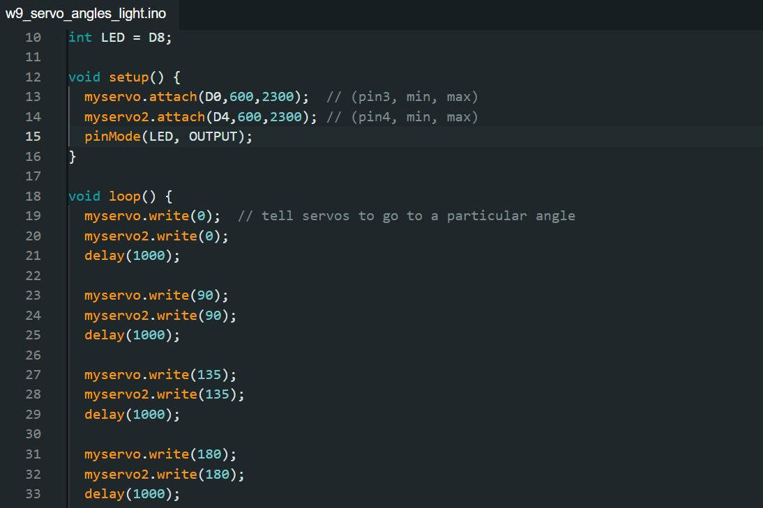
We can see that with the same given power supply of 5.1V the current used by both servos increased. For the second and third change of angle, the current consumption was around ~4.A but for the first angle and coming back from 180 to 0 position the consumption went up to around ~25.A the current consumption of the Blinking light was unnoticeable.
-Learning Outcome
For this week the most challenging part was the theory of the Motors how they work inside. As I did the output with Servo Motors it was quite easy to do the connections, there is plenty of information on the web on how to connect them and move them. I decided to use these motors as they will be in my final project. The most challengng part was the coding and how to make them move, so far I used simple codes I found in internet and tweaked them a little bit, but I would like to do more complex movements and for it I need to explore more into the coding of the servo motors.