dummy
14.NETWORKING AND COMMUNICATIONS
Networking and communications are very important subjects for my Final project (link) as I plan to use the I2C BUS serial communication to communicate between the “Kinetic Curtain” modules.
This week was quite hectic as I attempted to tackle multiple tasks. Some of the things I focused on were:
- Experimenting with the Sensor light on the Final Project Main Board, see W12.Input devices.
- Retrying the mold from the previous week, this time using Silicone and casting the final objects, see W13.Molding and casting.
- Creating the designs for Peripheral PCB modules and milling them for the Final Project. I had two options and both were meant to use the I2C BUS for this week assignment. Unfortunately, I was unable to complete the programming for them, see Final Project.
- Troubleshooting the Rotation Mechanism for my Final Project modules, see Final Project.
HERO IMAGE
ASSIGNMENTS
Gropup Assignment
- Send a message between two projects
Individual Assignment
- Design, build, and connect wired or wireless node(s) with network or bus addresses.
GROUP ASSIGNMENT
We attempted to establish an I2C BUS Communication between us by using Arduino UNO Microcontrollers. To guide us on how to accomplish this, we followed tutorials from Instructables and Aranacorp, which we found online.
It's worth noting that throughout this writing process, we referred to the "Master" board as the "Mainboard", and the "Slaves" boards as "Peripherals".
Afterward, we connected the Peripheral boards to the Main Board using jumpers. To do this, we utilized the pins A4 (SDA) and A5 (SDL), ensuring that we always connected A4 to A4 and A5 to A5 between the boards. We also made sure to connect all the boards from Ground to Ground for proper communication.
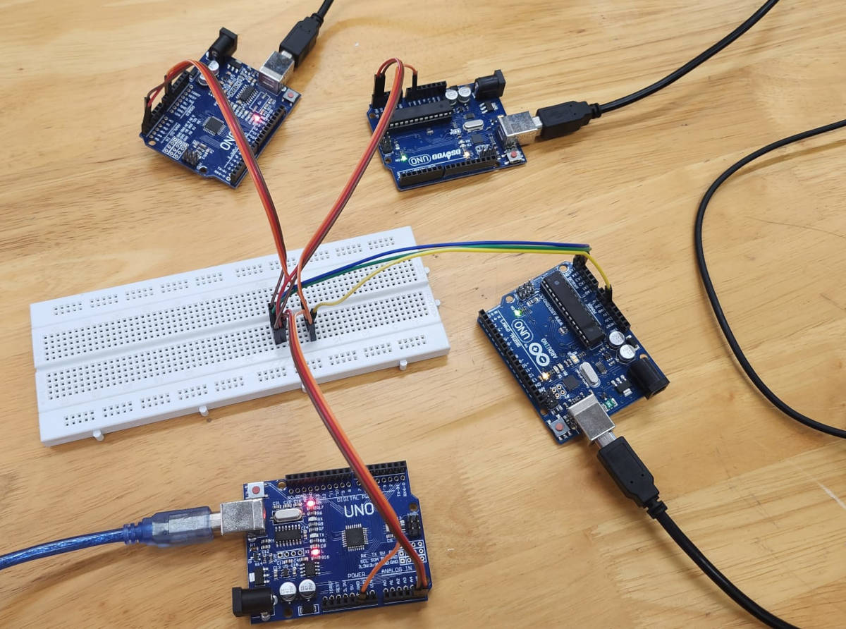
After connecting all the boards and uploading the LED light On/Off programs, we tried to establish communication between them. Unfortunately, we found that the setup wasn't functioning as expected.
During the troubleshooting process, we verified that the connections between the boards were correctly established. However, when the Main Board attempted to send instructions to turn the LED light on or off to the peripherals, there was no response
We suspect that the issue might be due to the lack of Pull-up resistors in the system. We plan to try again and run the protocol with the connections completed in the next few days.
You can see HERE more about the group assignment.
INDIVIDUAL ASSIGNMENT
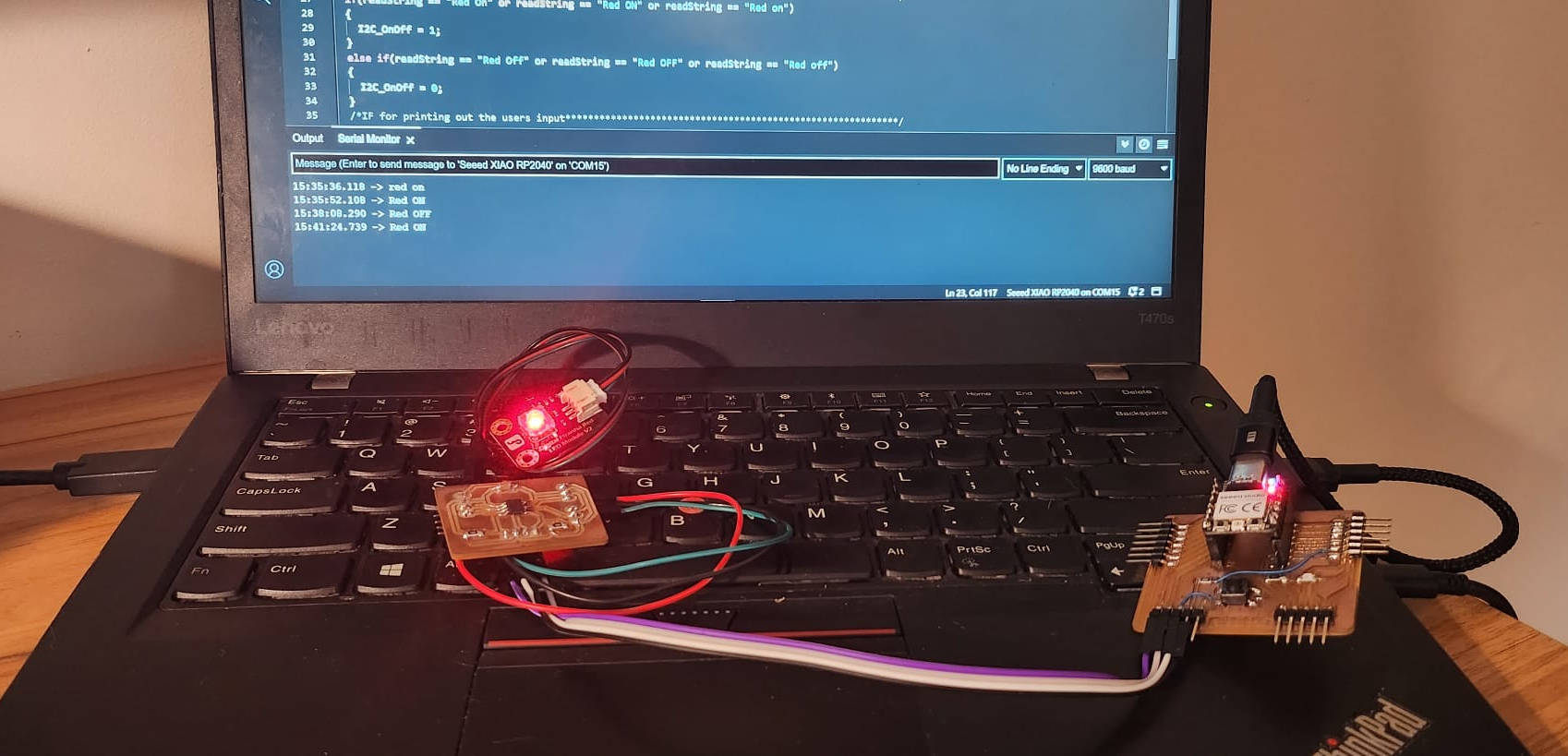
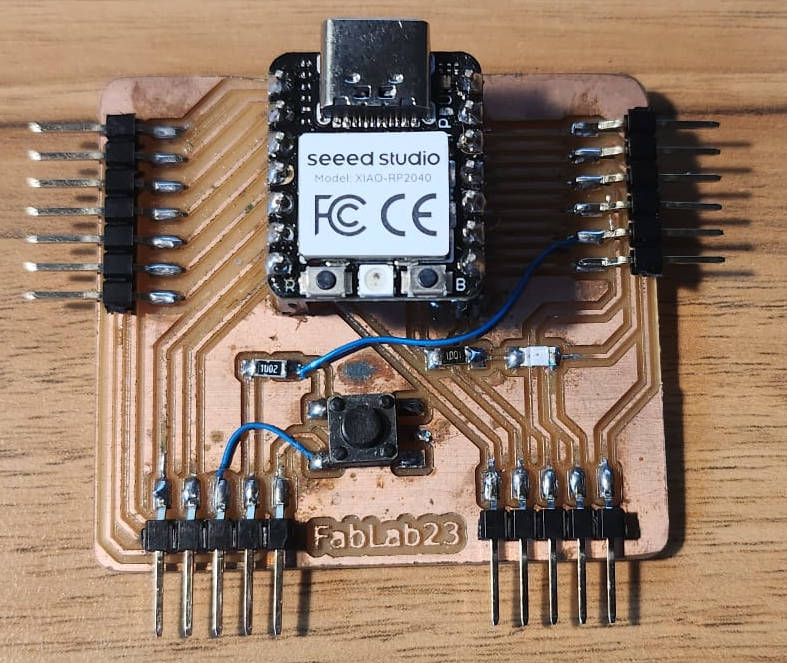
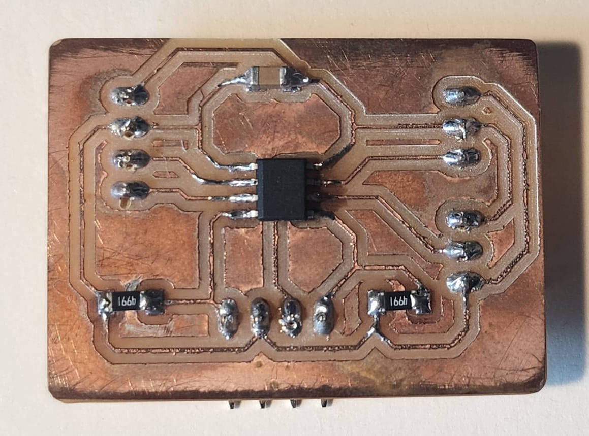
I decided to connect two of the PCBs that I made: the XIAO board from week 6 electronics design and the Main Board from my final project. I used an I2C BUS connection to link the two boards.
|
|
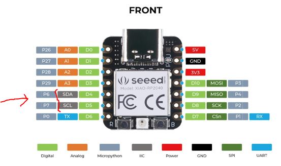
The Pinout of the XIAO RP2040 board indicated that Pins D4 and D5 are SDA and SCL, respectively. Therefore, I used these pins to connect the I2C protocol connection along with the ground and VCC.
Connecting the XIAO RP 2040 board to the ATtiny 412 board of the Final project was easy, as I already had the pinout for the SDA and SCL. Additionally, the board has pull-up resistors that are essential for an I2C BUS circuit.
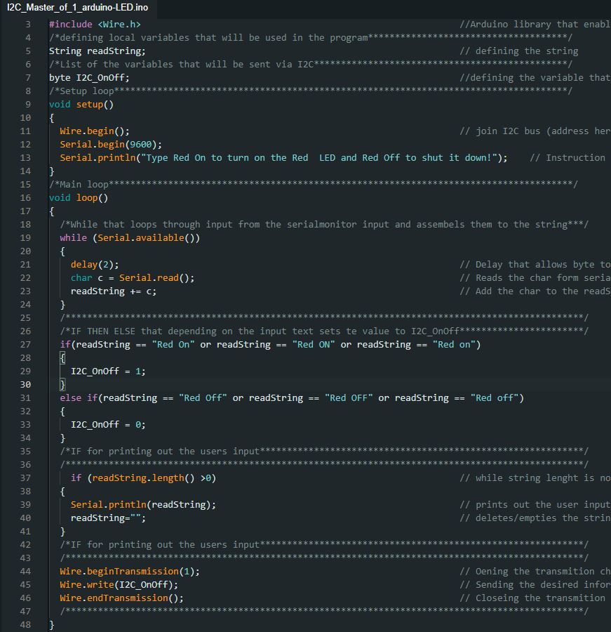
To establish communication between the XIAO RP2040 and the ATtiny 412, I set up the XIAO as the main board and the ATtiny 412 as the peripheral board. Following a tutorial from Autodesk Instructables on connecting Arduino UNO boards, I used the code examples provided to program the main board to send instructions to the peripheral board to turn ON or OFF an LED light. For this purpose, I connected the LED light to Pin 4 of the ATtiny 412.
Main Board Code:
Peripheral Board Code
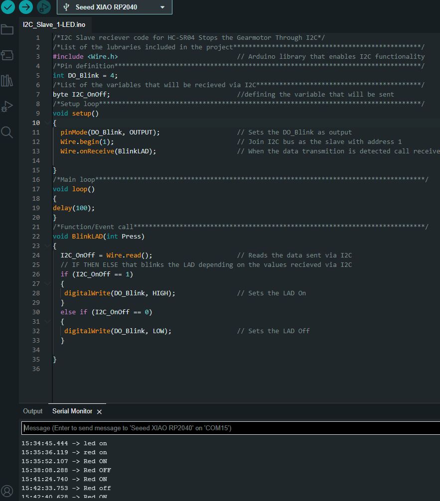
We can observe that when the command "Red On" is entered, the LED turns on and the message can be read in the Peripheral code as well. Similarly, when the command "Red Off" is entered, the LED turns off.