dummy
2. COMPUTER AIDED DESIGN
This week we should experiment with programs that allow us to present our ideas in a digital way, with 2D and 3D programs. We will start to work on the idea of the Final project digitally using “Vector” programs for 2D and 3D a programs that allows us to make a video of the model.
Hero Images
Vector Image, final Project Logo
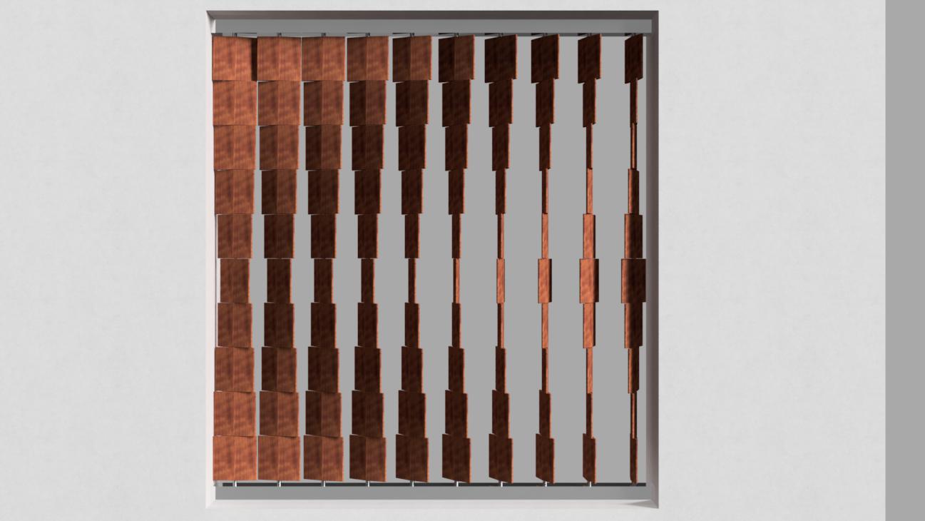
Model Render preview image
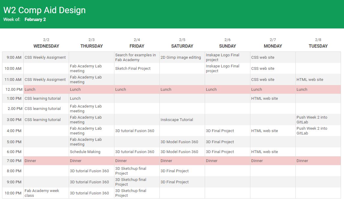
Week schedule
I find it very difficult to work in parallel on the assignments, so I did a schedule to keep track that I am working in this way…but until now is more like a diary of how I have assigned the time to work during the week. I started with a work schedule but I am not able to follow it, my brain is set to work in a linear way.
Assigments
- Generate a Vector image of the Final Project.
- Make a Model of the final project.
- Making a Render of the model.
- Make a Video of the model.
- Compression of the video for web.
- Raster images and editing them
- Final Project page update.
- Upload the files of the Model and the Vector Image.
Research
For this week I have used a lot of Youtube tutorials for the programs and lots of Google search to solve the problems and questions I found on the way, these are some of them:
- Vector 2D program
INSCAPE HALFTONE - Raster Image
GIMP, Google search - 3D Modeling, rendering, and Video
Autodesk Fusion 360:
USER INTERFACE
GETTING STARTED CREATING ANIMATIONS IN FUSION 360 - Video Compression
Handbrake:
HOW TO COMPRESS VIDEOS WITHOUT LOSING QUALITY
Generate a Vector Image of the Final Project
A vector image program allows us to compose and edit vector graphic images that are created from basic geometric shapes defined by an X, Y plane (2 Dimensional). These shapes can be lines, points, curves, and polygons.
I used INKSCAPE which is an open-source program to design the logo for the FINAL PROJECT Kinetic Curtains.
The design idea of the curtains is that they filter the sunlight giving a quality of light that is managed by the rotating elements, I used the Halftone Pattern from the program to design a Logo that emulates this movement and the filtration of the light.
First I created a clone from a circle filled with white, this original clone will be a component that will be repeated to create a pattern later and can later modified all the copies of it.
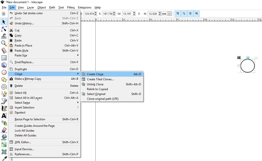
Before continuing, I made sure the clone was working, opening the tool "clone to create tiled clones", I made some copies. If I changed the clone all the copies will change, in color, shape, etc.
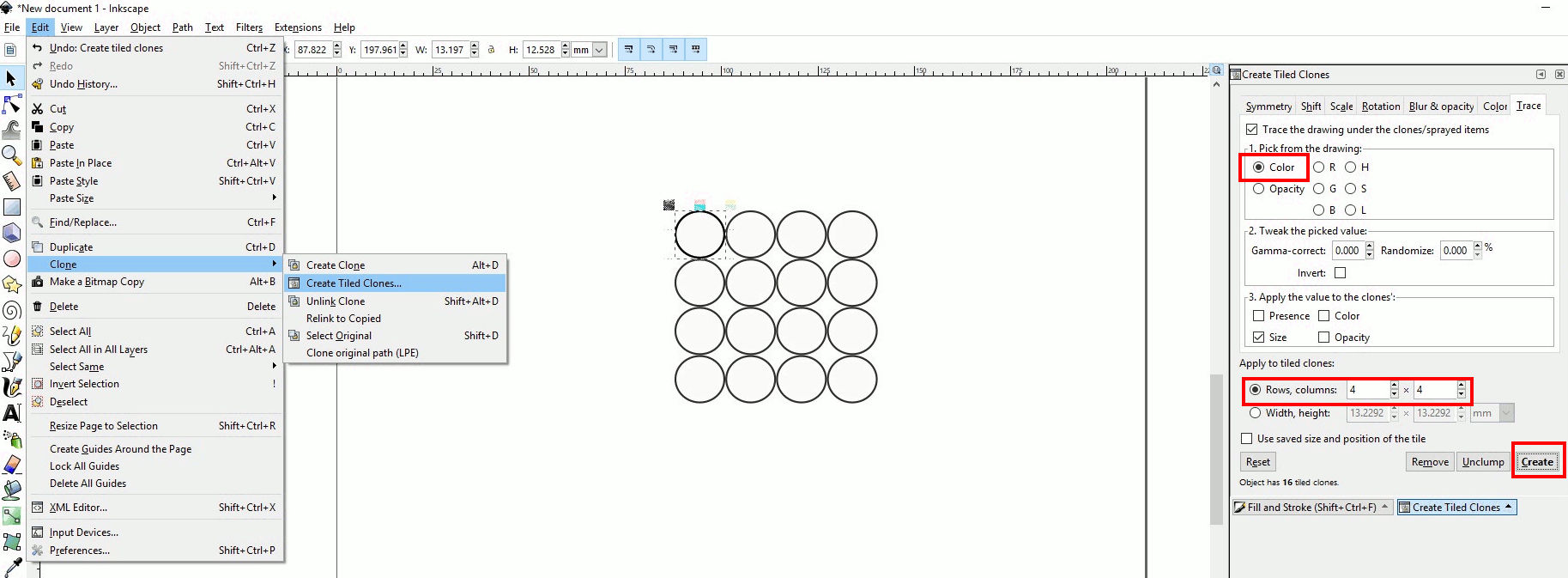
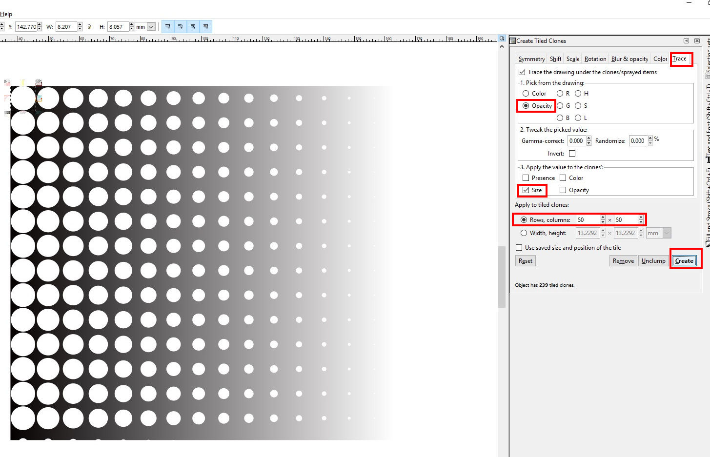
Then I made a square with a horizontal gradient that I chose in the palette of “Fill and Stroke”. I continued with the Palette “create tiled clones” and made the initial pattern to follow the gradient of a square ticking the trace tag, opacity, size, and quantity of rows
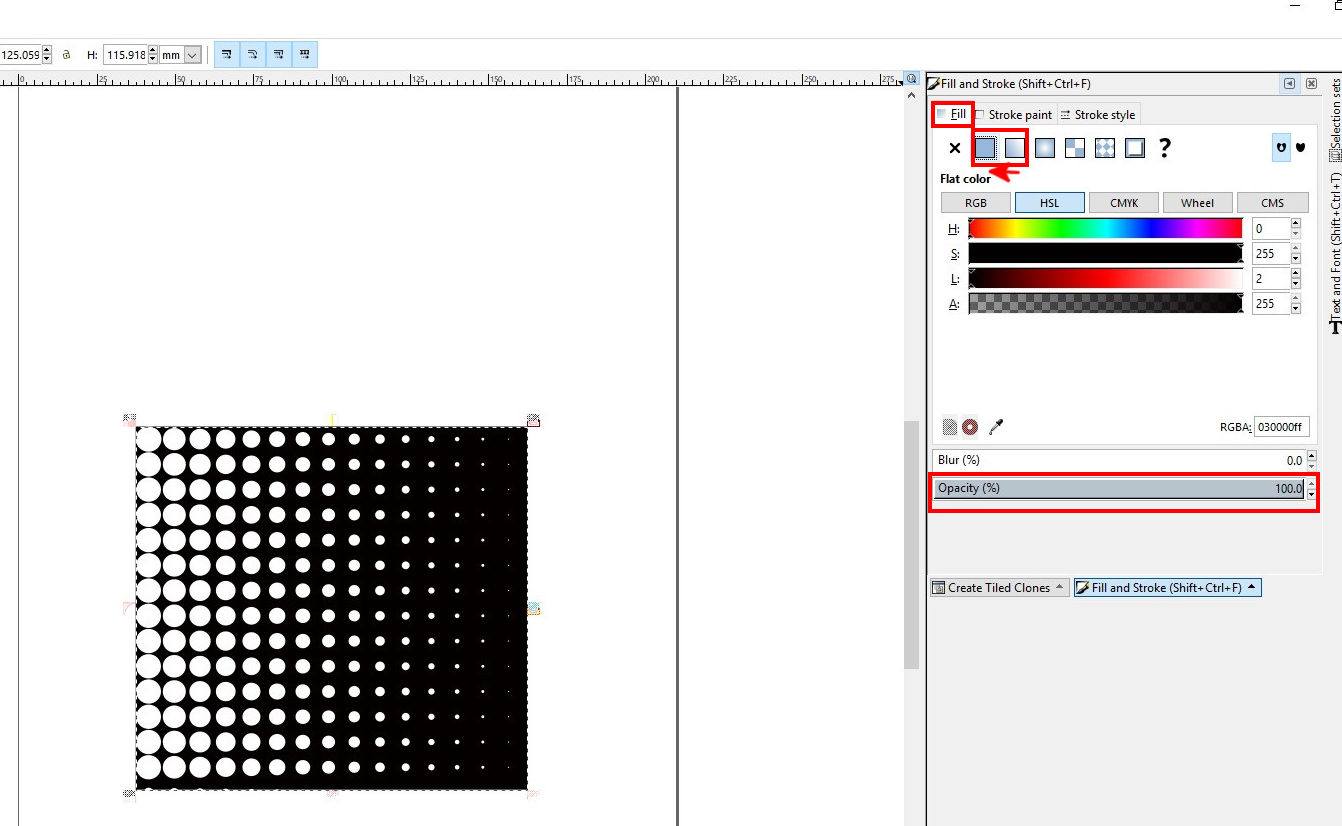
As I want the square to be a solid color I went back to the “fill and stroke” window and changed the fill to be solid.
Clicking the “Text” tag, I wrote the name of the product which in this case will be: Quality Of Light. It is possible to change the text properties, in the upper part of the window, the name of the font, the spacing of the letters, the alignment, etc.
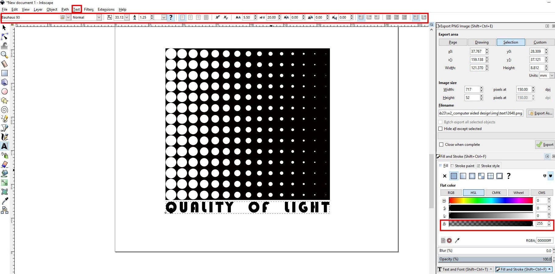
I continue editing the picture a bit further making the square a bit bigger, locating the text inside the square, then changing the color of the text so it can be read. I saved the file as a PNG. Later I changed the size in GIMP to upload it into the web.
Make a Model of the Final Project
I decided to try a new program for me, I am used to working with Autocad from Autodesk and SketchUp from Trimble, but these two programs are not “parametric” so I wanted to start to dive into the parametric programs. I chose Fusion 360 from Autodesk, it is a very friendly “parametric” program to start with, I had expected it to be simple to work with as I knew Autocad from the same company…but that was far from reality.
Frustration and a way to go out of it...SketchUp
I tried to model in Fusion 360 as I did with Autocad or in SketchUp but it wasn't that easy, it took me several Tutorials to understand the logic of the program.
There is a 2D mode called Sketch, then a 3D mode which is called Object, and both of them even if they are correlated are in different “modes” that you have to enter in.
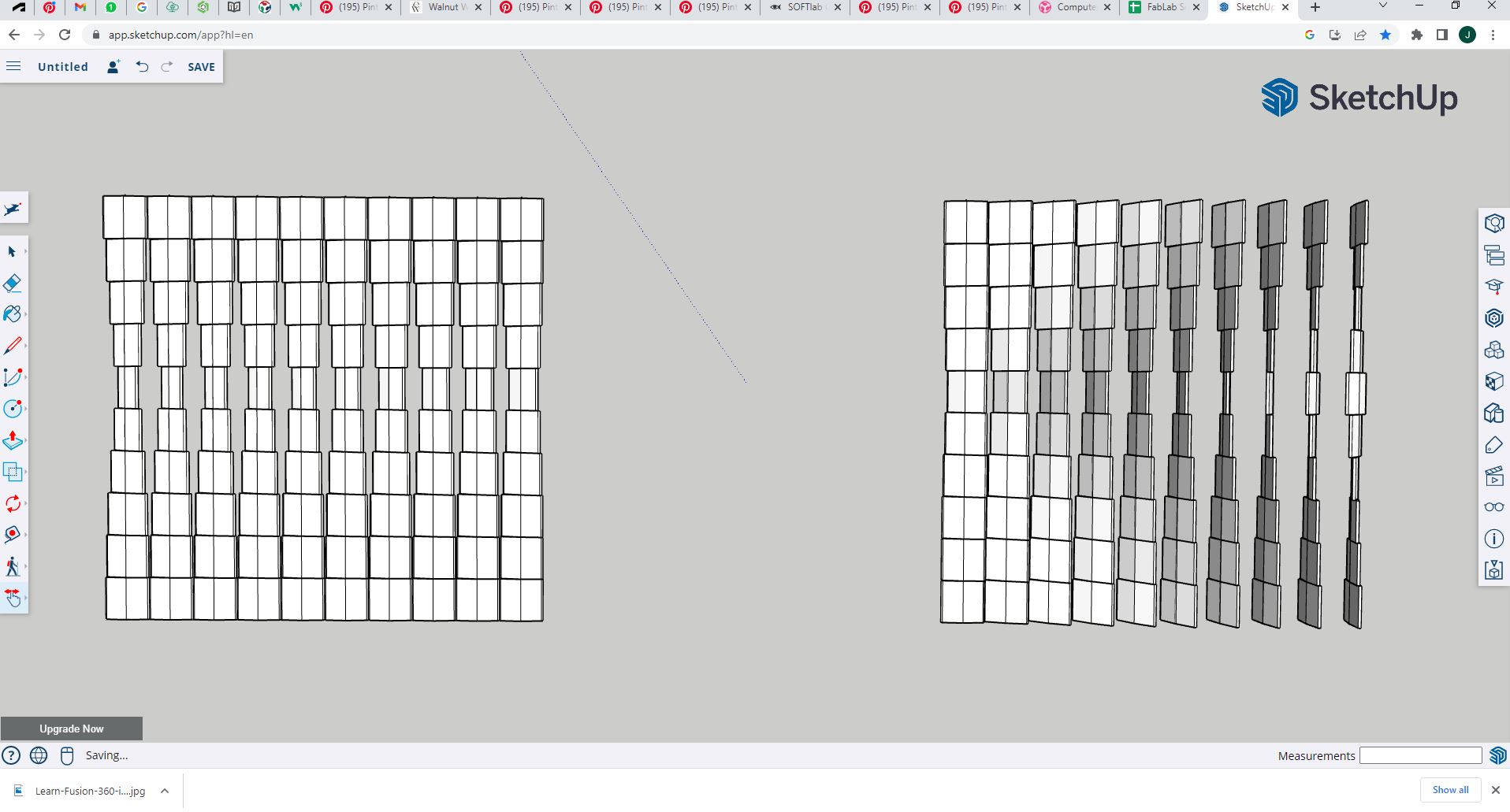
As I mentioned I am very familiar with SketchUp and Cad which are very straightforward programs, when the first two days of the "week two" passed and I haven't started with the assignments and was stuck with the tutorials, I decided to make a fast sketch in SketchUp to go out of the hole and see if the idea I had in mind was feasible.
I draw a module that I made into a component, then I copied it vertically to create another component, and then I copy this component Horizontally. I rotate the components to create the effect of movement.
Fusion 360
Having the first sketch modeled, I knew what to draw in Fusion 360, so I moved back to this program to model the project.
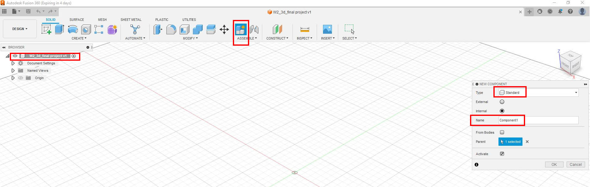
First I create a component (this is important for the moment to do the animation that is based on components)
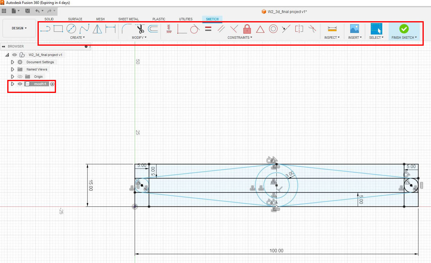
Inside this component, I started to create in the “sketch” mode the profile of the module that I wanted to repeat for the “Kinetic Curtain”. For this step, I drew the shape with circles and lines. It is very important that all the elements are constrained, meaning that if I change the value of any of the distances it will affect the value of other distances this is the basis of ”Parametric” design. The constraints in my drawing are basically distances and tangents between lines and circles.
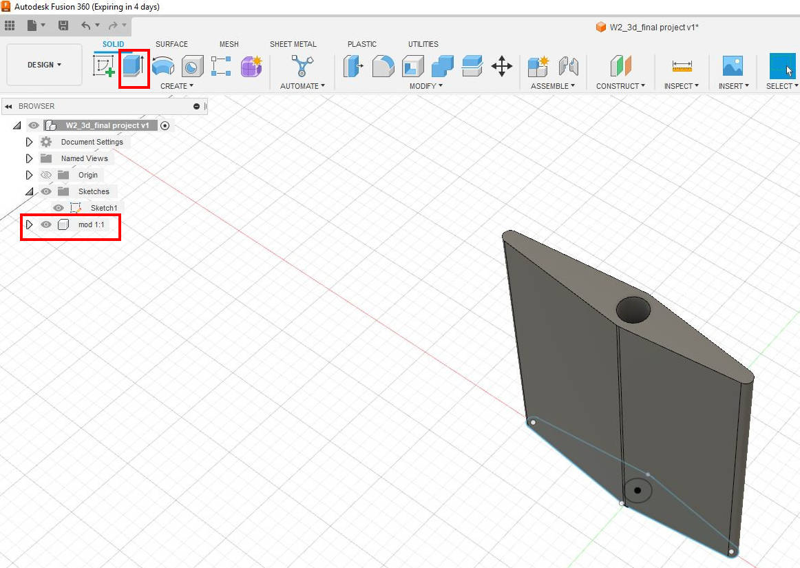
When the 2D drawing is ready it is possible to ” Extrude” the desired plane to create the first 3D module, it is done with the solid tools: “Extrude”, we enter the number value that we want in this case was 100mm
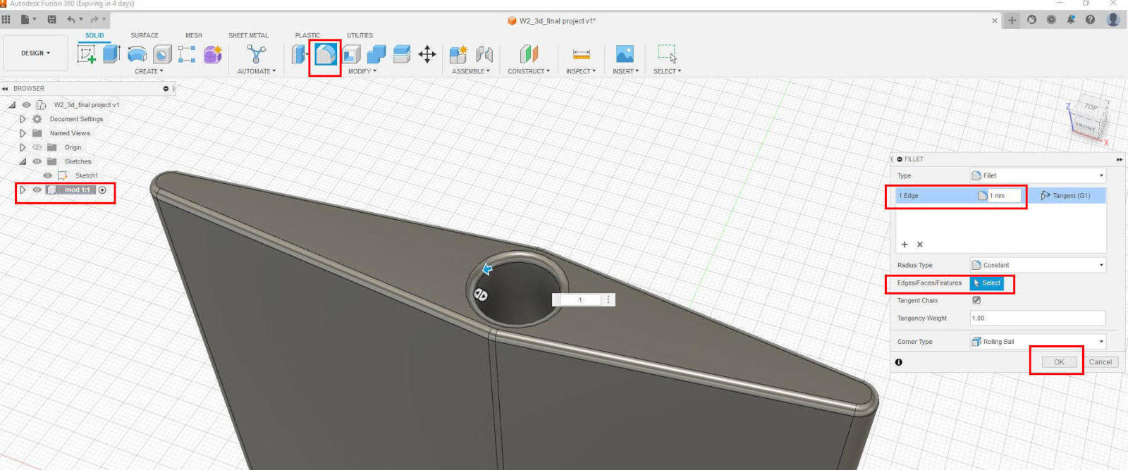
As this model will be manufactured I want it to have the edges rounded for a better finish, I assume it will be 3D printed (not yet sure). I applied the fillet tool from the “Modify” Pallete and wrote 1mm edge and rounded all the edges at the top and bottom.
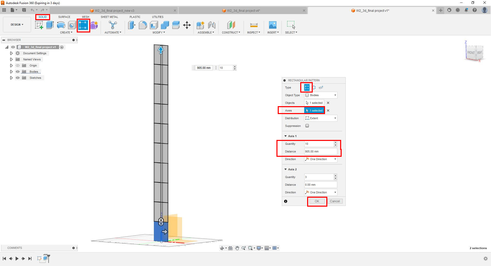
This initial module is the base for all the “Kinetic Curtain”, I open from the palette “solid” the “Rectangular Pattern tool” to copy this module in a vertical array, 10 times leaving a space between elements of 1mm
Pattern and Rotating problem...
a. When I used the “Rectangular Pattern” tool to copy the elements I couldn't figure out the possible equation for the elements to copy without me doing the calculations.
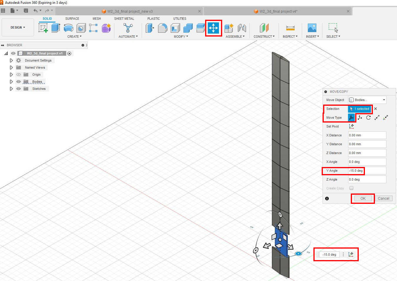
b. When I was doing the pattern I would’ve liked to have the modules copied and rotated at the same time. So I did it manually, I Patterned, then rotate each module individually changing the grade of rotation for each module
Searching on the web, I found a FORUM of Autodesk and it says apparently it is not possible to do what as I wanted.
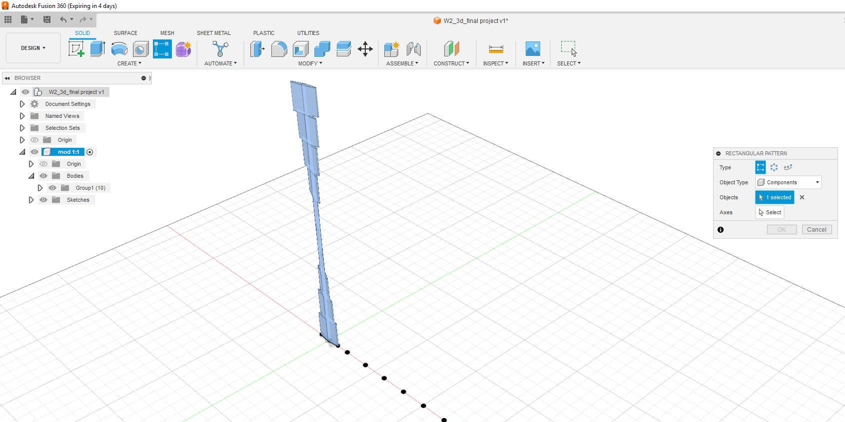
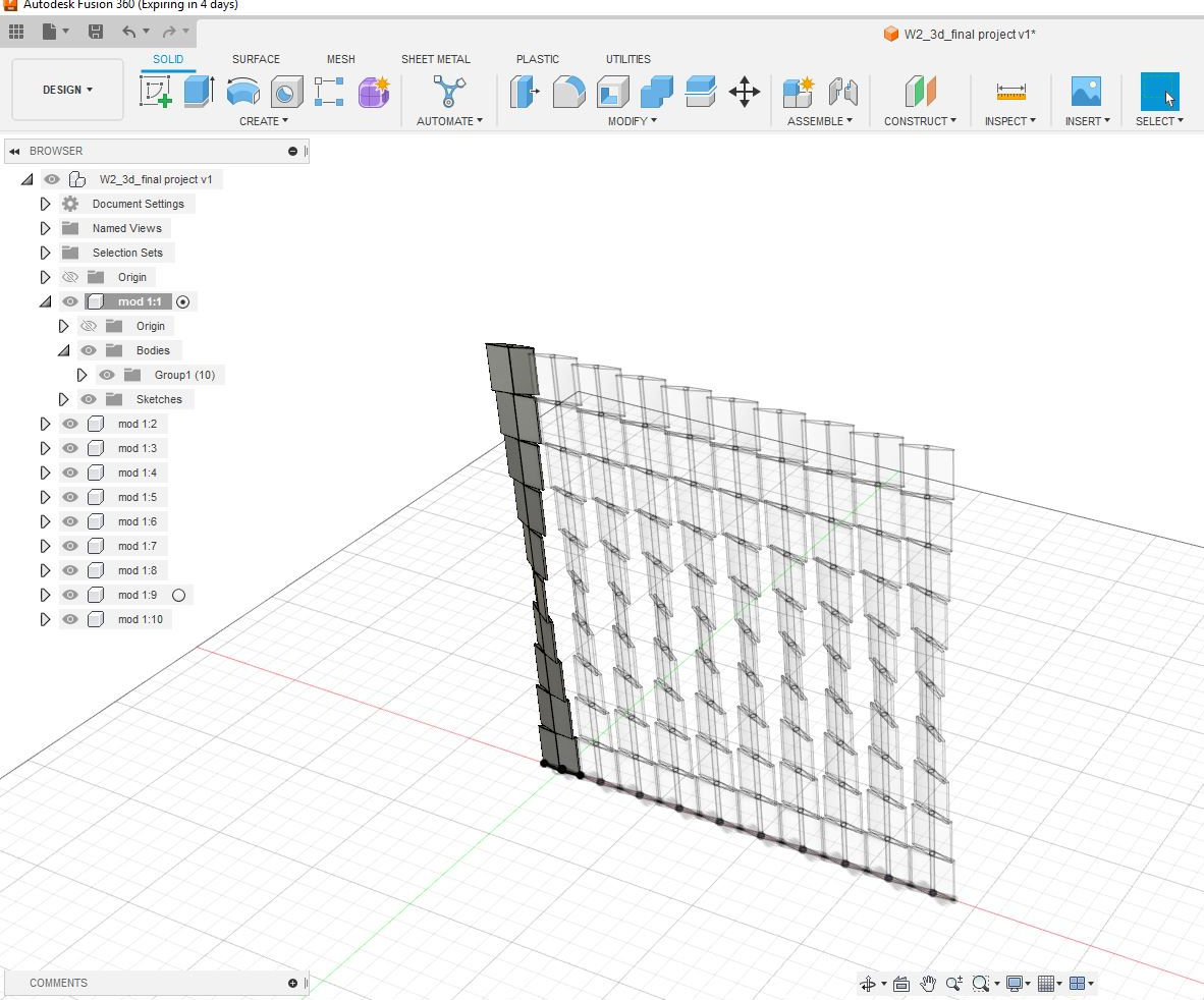
Moving forward having this vertical module, I “Patterned” it 10 times in the horizontal line and have all the curtain modules complete
But then again
Translucent problem...
The patterned elements appeared translucent and couldnt select them, I didn't know why, so again I did a google search, and got to know in a FORUM that to see all the 3D objects of the model as solid you have to go out of the component to the first root of the drawing and activate it.
Then I went to the beginning of the “root” and modeled the upper and lower profile that will support the vertical modules and the central rods where the modules will rotate. All the curtain system will be mounted in an open square of 1000mm x 1000mm. All these parts were modeled in independent components.And time to assign materials, for this we open the window "Modify" and look for the tool "Physical Material".
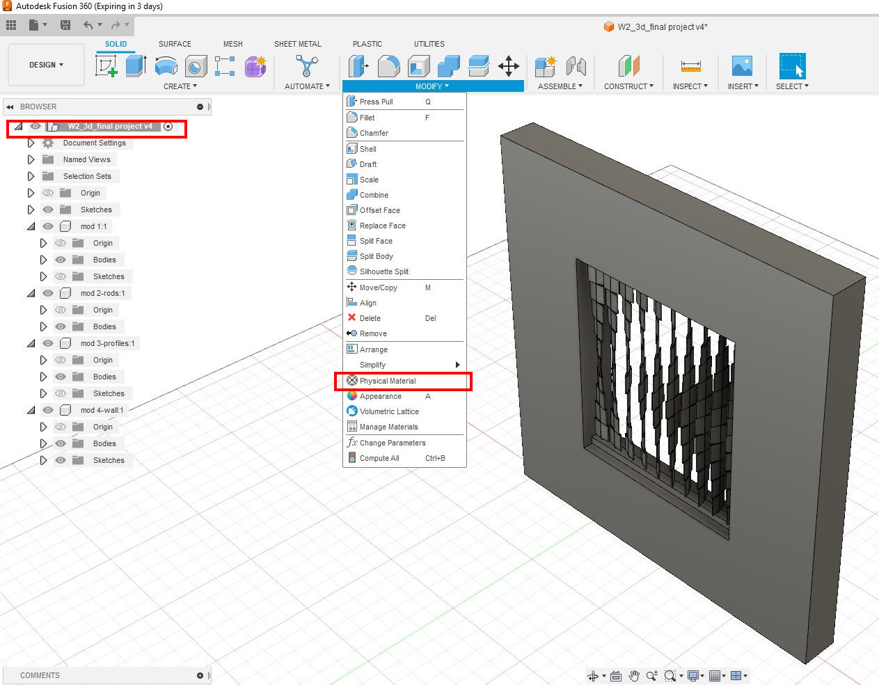
I wanted to assign materials to the curtain modules, the rods, the upper and lower profile, and the wall where the curtain is mounted. The materials are found in the “Modify” palette under the tool of “Physical Material.”
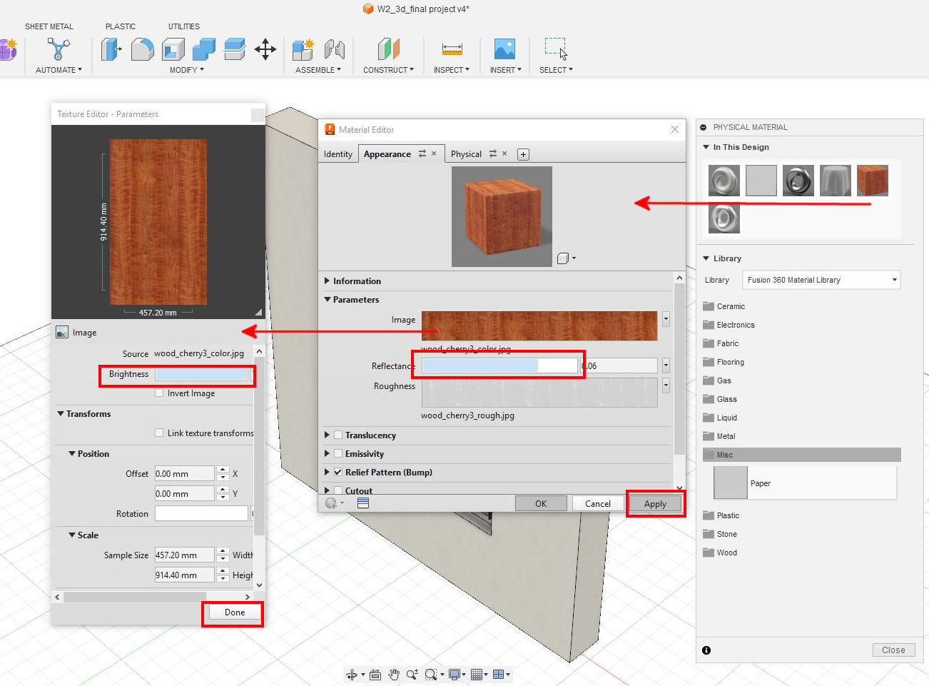
The materials can be edited in luminosity, size, color, etc…once is done we should apply the changes. I changed the reflectance in most of the materials as they were a bit dark.
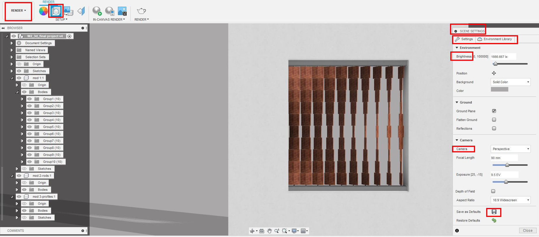
Making a render of The Model
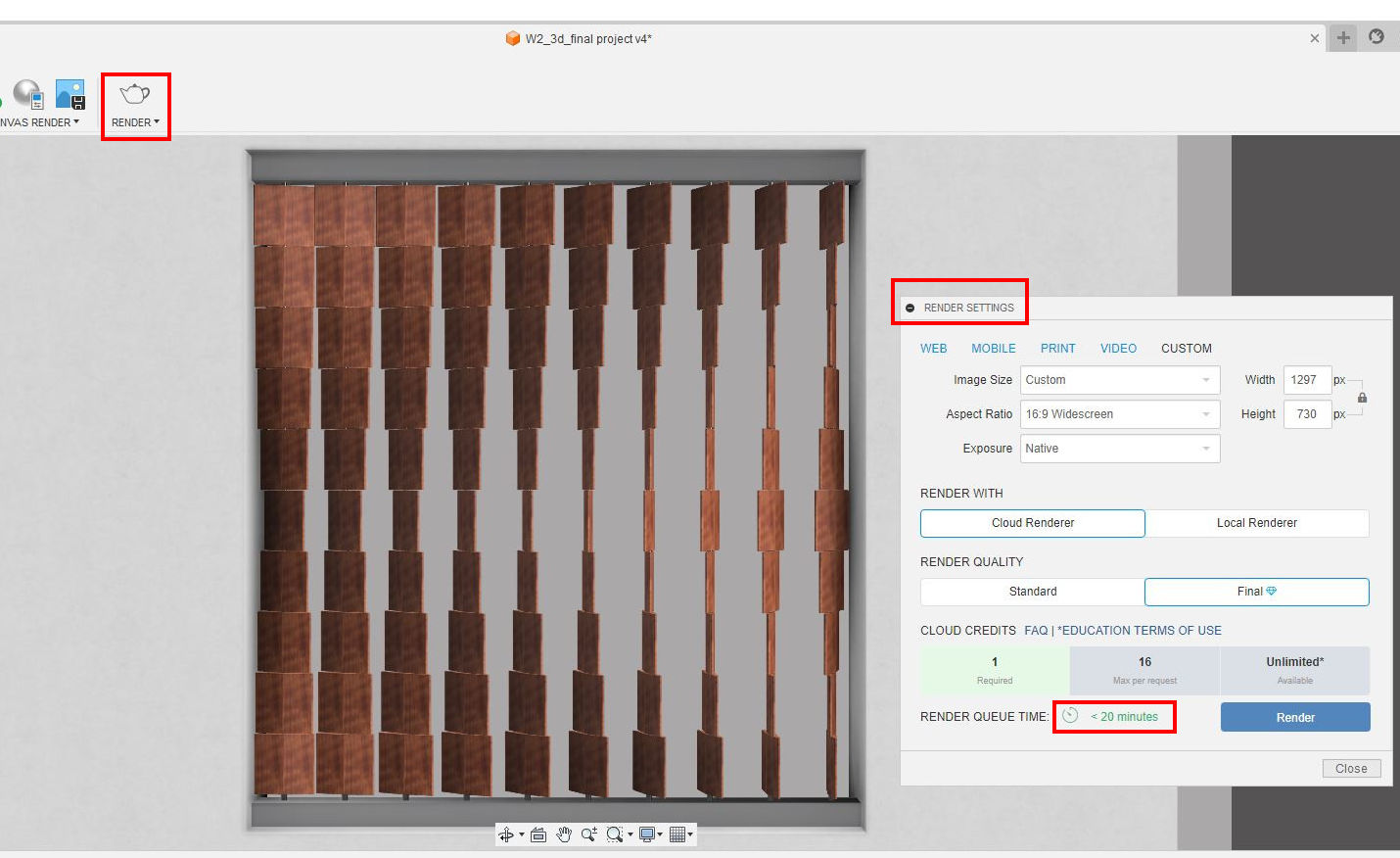
Once the materials are assigned it is the moment to move to the render window. There we find the “Scene Settings” tool. We can set there the brightness, camera angle, and exposure and save the settings, then in the tab Environmental library, we can choose the quality of the light, I chose a warm light.
If we want to have a fast look at the materials and light of the render we can set the In-Canvas Settings, which renders the image with good but not perfect quality, and it can be faster if we choose the “Fast” option. I did the fast option as my computer is not the most powerful on earth, and I didn't want it to crash.
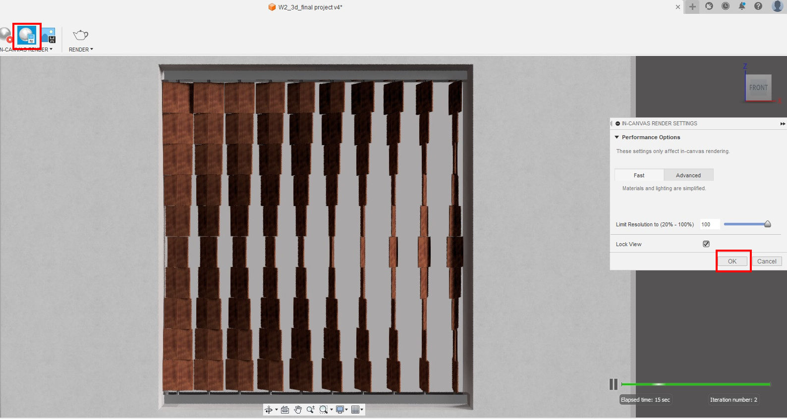
It is possible to do a Render with higher quality with the "render" tool, but it takes a longer time. In my case, it said 20min.
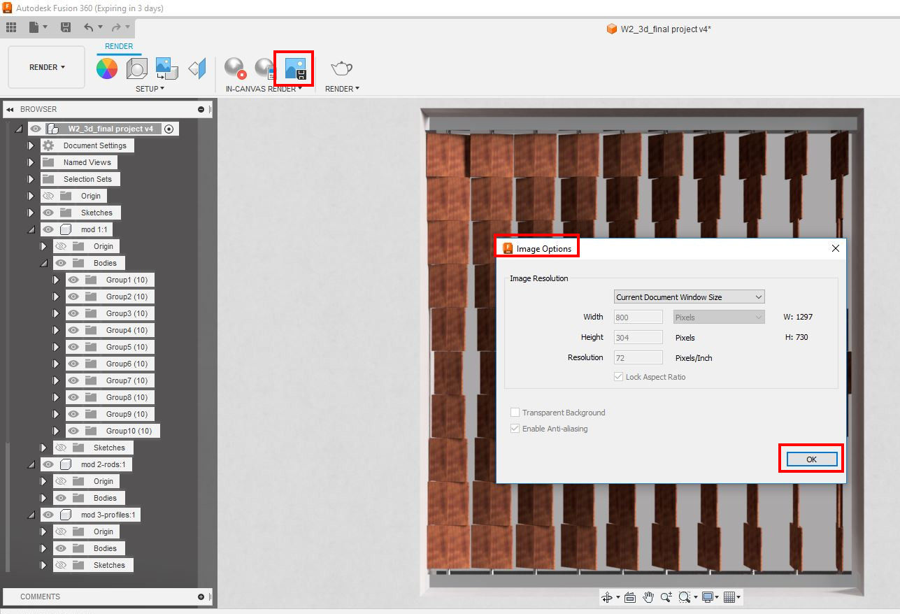
So I decided to go the fastest way, nevertheless, it is not the best image quality. To do so we have to use the “Capture Image” Tool. This tool is quite limiting as the size and pixels of the image are set and can not be modified. Once you hit the OK button you can save the image in the cloud or in the computer, I did it on the computer for later editing.
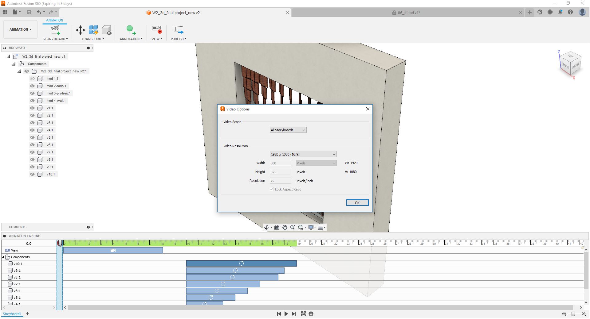
Make a Video of the Model
Fusion 360 has the option of making videos, it is straight forward, although I wanted to make an assembly video the time wasn't on my side.
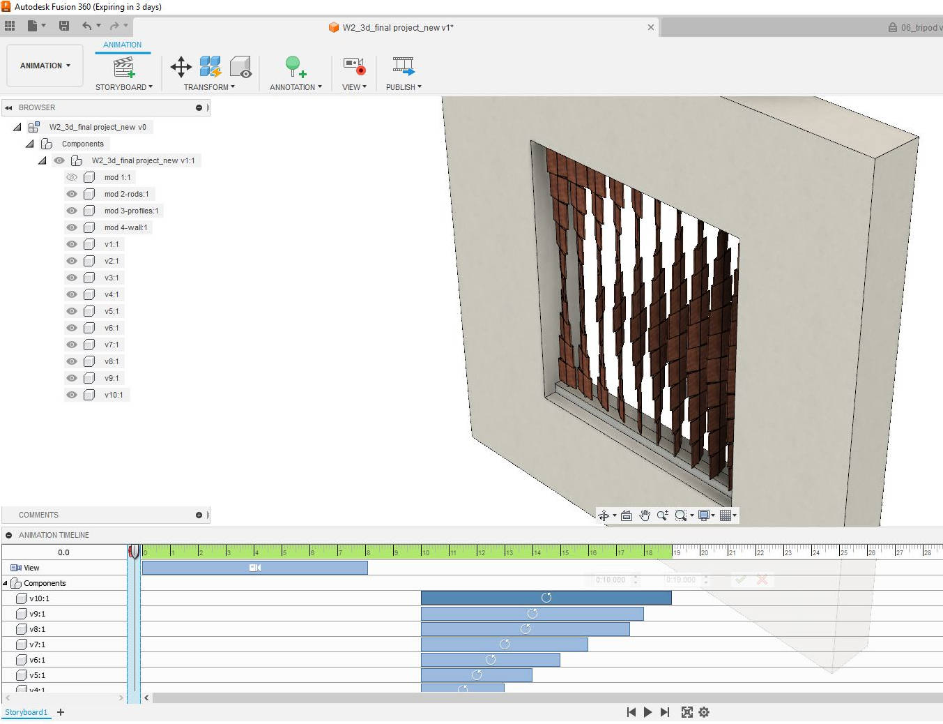
To make the video, we go to the Animation window, and under the screen, we find a dialogue box where we can set the movements of the different components. Note that it is important that all the parts we want to move separately should be in different components to do the movements.
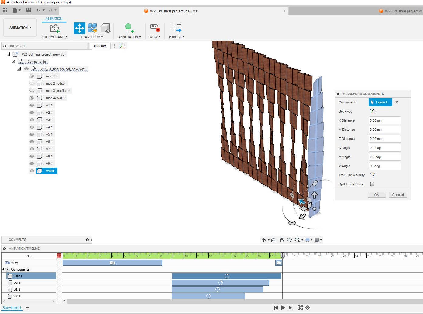
I wanted to rotate each of the vertical components in an independent manner for this I had to go to the Transform Components and a dialogue box opens where we can give the rotation angle, but prior to it we had to set the time we want this movement and when to start it, for the first vertical module I started at 9 seconds and finished at 18 seconds. Then I set the second to the last one.
The original view location is in perspective, I wanted to show how the “Kinetic Curtain would look from the front. So I set the time at 8 sec and move the orbit from perspective to front view.
To make the video was very useful the YOUTUBE TUTORIAL ,short and easy.
when the video is ready we go to the Icon "Publish" and save it in the desired location, I did it in my computer. The video is saved in format AVI, later with an encoder program I compressed and changed the format to MP4
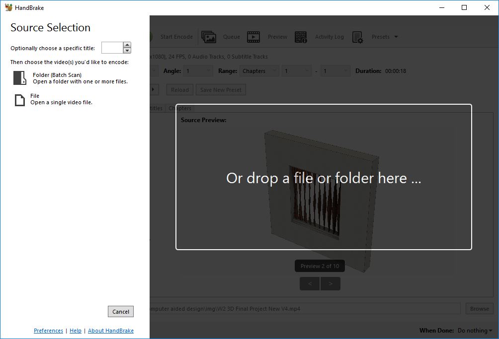
Compression of the Video for Web
I have used an open-source program called HANDBRAKE, it is very easy to navigate, and I have used a YOUTUBE TUTORIAL to help me go through it
First I downloaded the program, open it and open the file to edit.
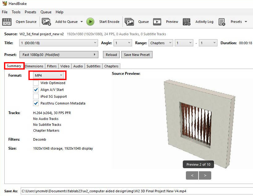
Once opened I went through the different variables to compress the video, in the window "Summary", I chose the format to be MP4 which is an universal format, and left the rest of the settings as they were.
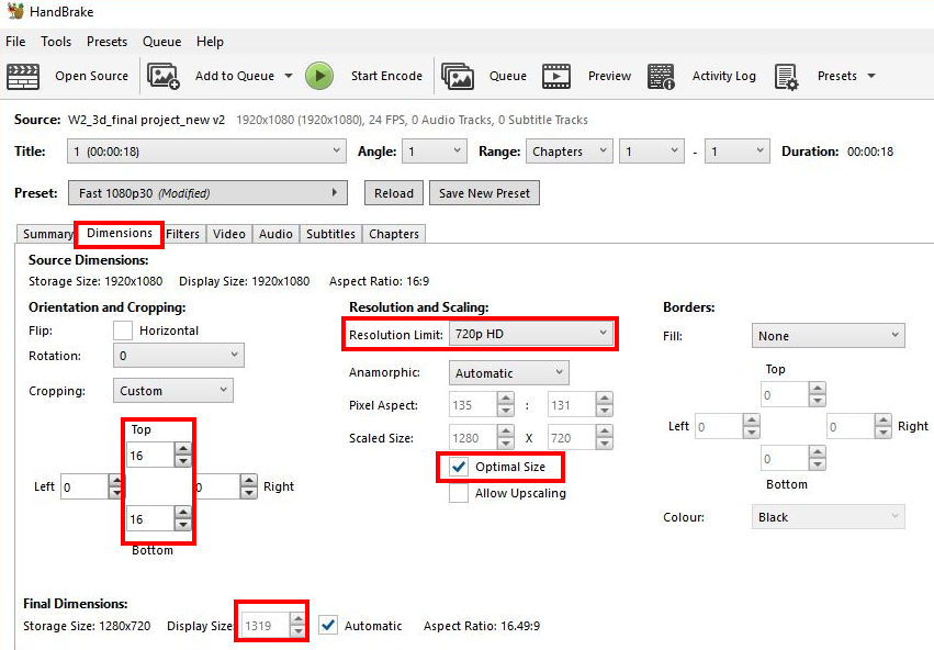
Then I moved to the Dimensions tag, here I cut the margins of the video at the top and the bottom this already made the video smaller. I changed the resolution Limit to 720p HD, and I left the rest as it was in the settings. (this made a video of around 10KB in size)
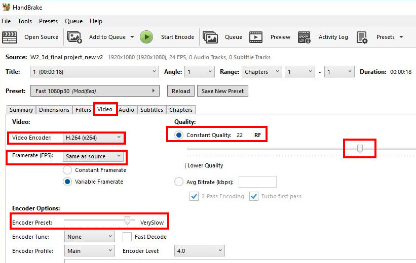
I moved to the “Video” Tag, where I chose the Video Encoder to be H.264, the most common, then changed the Encoder Options making the tag “Encoder preset” to Very Slow, this means the encoding or (compression) can take longer but the quality of the video and size of the file could be smaller (according to the youtube tutorial). Then I left the Quality of the video at 22 (should be between 20 and 23 for good-quality iresolution) and then I left the rest of the options as they were pre-set.
Handbrake has a tool at the top "Preview", where we can see the changes before saving the video
Raster Images and Editing them
Here is where all the screenshots and images I have created during the week have to be edited to make sure they have a good size for web , I use GIMP, again an open-source program very similar to Photoshop from Adobe.
This program works as a Raster, meaning the information of the image is given by the quality and quantity of the pixels. We can edit the appearance of the image making changes to it, like colors, shapes, layers, text, etc.
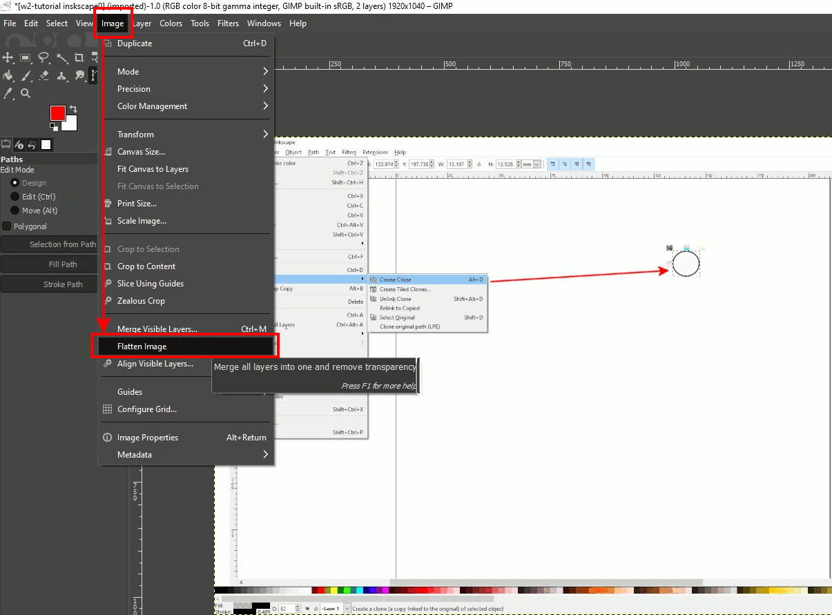
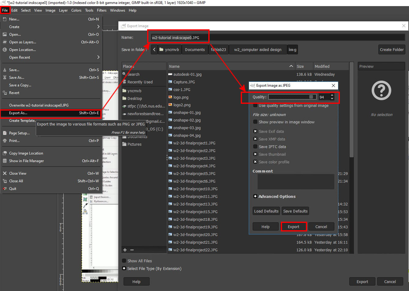
I opened the desired image to Edit in GIMP, then I marked with rectangles and arrows the sequence of steps, this was automatically sent to a new layer. To save the image in a lower resolution first we have to flatten the image from the Image tag.
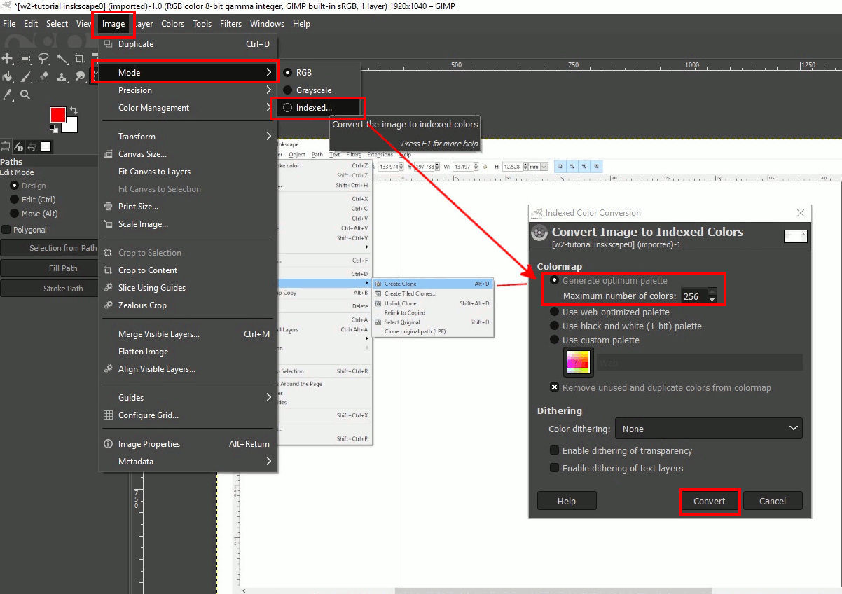
As the file is going to be uploaded to the web, I changed the Color mode in the Image tag to Indexed and 256 px colors, then we hit convert.
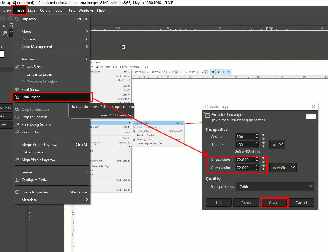
Then we change the image size, for our storage limit on GitLab it is advisable to push images around 200KB.
Then we save and there is a last compresion, I did 90%
Problem resolution
The images edit final result was a bit blurry even do they are more than 300KB, if I make the files smaller it is not possible to read the text at all. I am wondering if this is happening because during the week I was “Snipping” and saving the files as JPG, when we do this the images save in a lower format. Then I open them in GIMP and edit them but they were already in low resolution.
Final Project Page Update
This week, I worked a bit deeper into the "Kinetic Curtain" design, I found some similar projects done by students of Fab Academy.
The modeling practice of the assignment helped me to understand more about the system mechanics of the design. Please see these more in detail under week 2 of the Final Project Link