dummy
FINAL PROJECT
IDEA
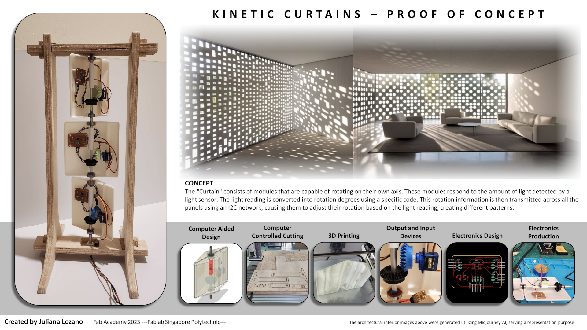
1. "Kinetic Curtains"
Kinetic Facades in Architecture refer to elements that are responsive to changing stimuli in relation to mechanical elements, pattern use, and material properties.
The use of response facades has been used since modern Architecture, at the beginning, the elements were static e,g. "Brise Soleil", made of concrete. Nowadays the elements can be built from different materials that can change shape or position with light stimuli with the use of program software, giving different types of facade design compositions and changing the quality of light at the interior of the buildings.

Eyelid-like concrete window covers at Centennial Concert Hall ©www.thebohemianblog.com/
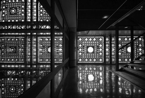
Arab World Institute by Jean Nouvelle

Dynamic Windows by Hoberman
For my Final Project, I proposed the concept of "Kinetic Curtains" that differs from Kinetic Facades. Unlike Kinetic Facades, which are integrated into the building design and cannot be controlled by users, I design the Kinetic Curtain for individual use. It allows people inside the building to have control over the quality and quantity of light using a remote control. The remote control comes with preprogrammed settings specifically designed for adjusting the "curtains".
In addition, the Kinetic Curtain incorporates a light sensor that detects the amount of light present. This information is then used to determine the appropriate angles at which the modules of the curtain should rotate. By adjusting these angles, the Kinetic Curtain effectively regulates the entry of light into the space.
Due to the complexity of this project, it is advisable to develop it in phases. Considering the time constraint of 20 weeks, I have decided to begin with the prototype design phase, focusing on a limited number of modules that respond to the values detected by the light sensor. These initial modules will be designed to move in accordance with the light sensor readings, serving as a starting point for further development.
2. Key design concepts
- MODULE DESIGN: The design of the module involves rotating mechanical elements around an axis. Considerations include the selection of materials and determining the method of rotation.
- ELECTRICAL DESIGN: My task is to design the necessary boards to control the modules using a Network System. This involves connecting various components responsible for moving the "curtain" modules and establishing communication between the boards.
- PROGRAMMING: This aspect poses the greatest challenge for me due to my limited experience and knowledge. I need to program various settings for the "curtain" modules, which requires acquiring programming skills.
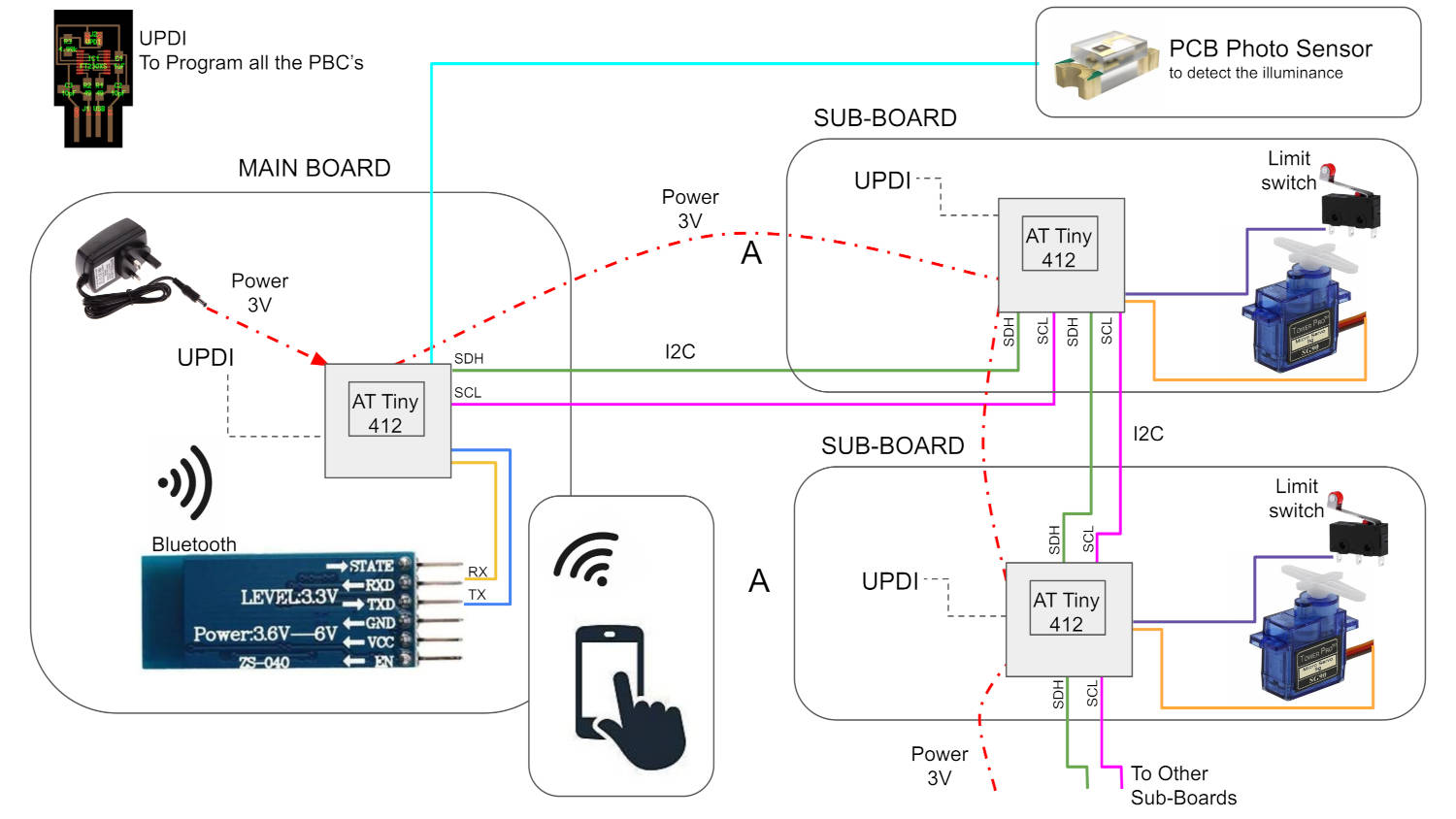
In order to facilitate rotation, each module contains a Servo motor controlled by a Sub-Board and powered by a battery. The Sub-Board will establish a connection with a Mainboard via a Bluetooth Mesh networ, later as I made a small prototype the power came from the main board and the Network connection was through I2C Networking.
The main board will be connected to the light sensor, since there is only one source of natural light. In this case, it is assumed that all the modules are positioned in a window with the same sun exposure.
The PCB boards can be manufactured in the lab using an AT Tiny 412 Microcontroller, considering that there is no requirement for extensive connections.
In the main board, I will connect a light sensor and a Bluetooth component, both requiring only three signal pins (as pointed out, I changed the comunication protocol to I2C Networking). The sub-boards, on the other hand, will need to be connected to a Bluetooth component and a servo motor. Each board will be powered by an individual battery and will have pinouts for connecting to an UPDI (Unified Program and Debug Interface) for uploading the programmed movement, (the individual power supply was changed for supply coming from the main board and distributed through the I2C connection cables.
3. Circular Progress
I broke the project into different phases to make it more manageable.
- Understanding the Project design's general concept, its parts and complexity, and giving the boundaries to the project stages.
- Making a prototype of ONE module, where I solve the mechanical rotation with a Servo Motor.
- Making the PCBs for the main Board, and the sub-boards that will be inside each prototype module.
- Programming the rotation of ONE module prototype and connecting with a Network protocol.
- Make another identical prototype and program with the existing one to communicate with the Bluetooth Mesh.
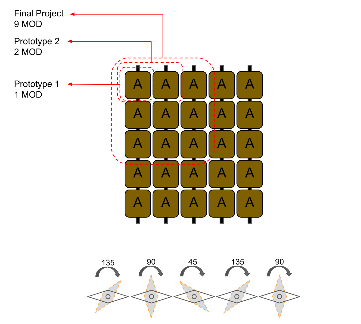
- Final prototyping with three to nine modules. I will do this number as it is manageable and the PCBs can be fabricated in the Lab. The programming can be very complex so I have to leave enough time for it.
4. Research
- Kinetic design
- How to pivot the modules
- Materials
- Sun light sensors
- Networking Systems
5. Fab Academy similar projects
Fab Academy has several documented projects where we can find the solution to potential problems or designs we are looking for. This is a list of some Student examples that made Kinetic facades:
- Interactive Architecture Kit (LINK)
- Interactive Modular Block (LINK)
- Dynamic Facade (LINK)
This project has a valuable aspect: the vertical elements of the facade can rotate. This feature is similar to what I want to accomplish in my own project.
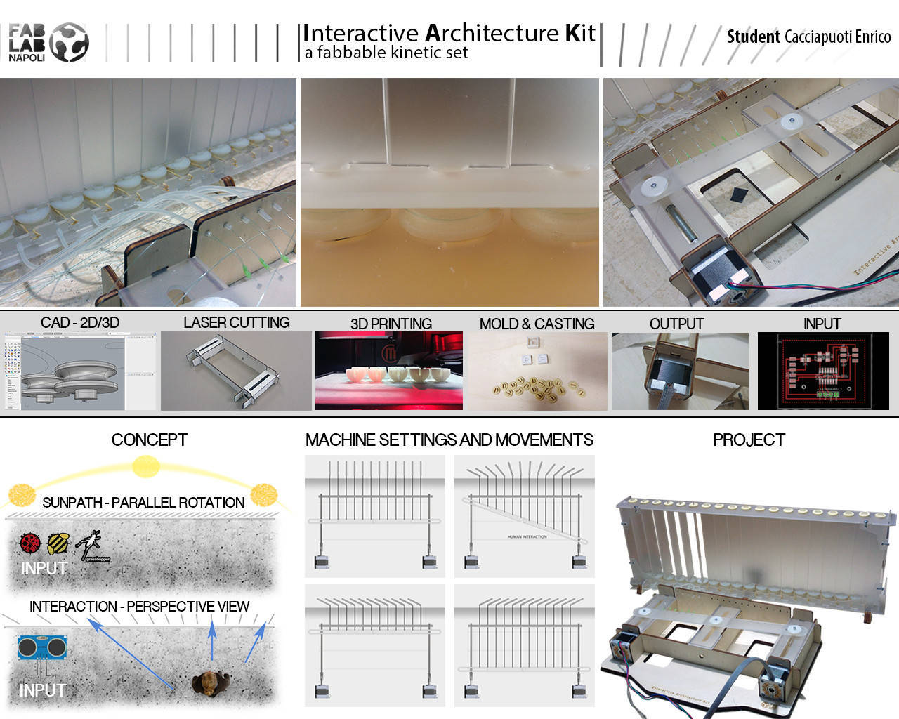
This Student made reference in her page to another project that is just what I want to do...lesson: almost everything is invented!
This is good news for me, as I can use this project as a reference, unlukily is not from Fab Academy so it is not documented, but it gives me a hope that it can be done.
This Student works with the rotation of vertical modules in a kinetic facade, which I propose in my project, it has a good collection of details of the 3d printed parts
DESIGN PROCESS
1. 2D and 3D Concept Modeling
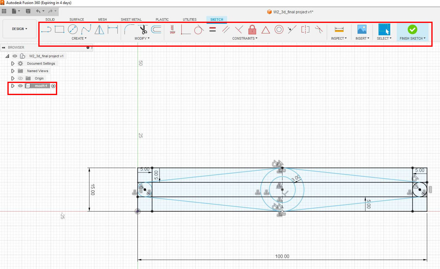
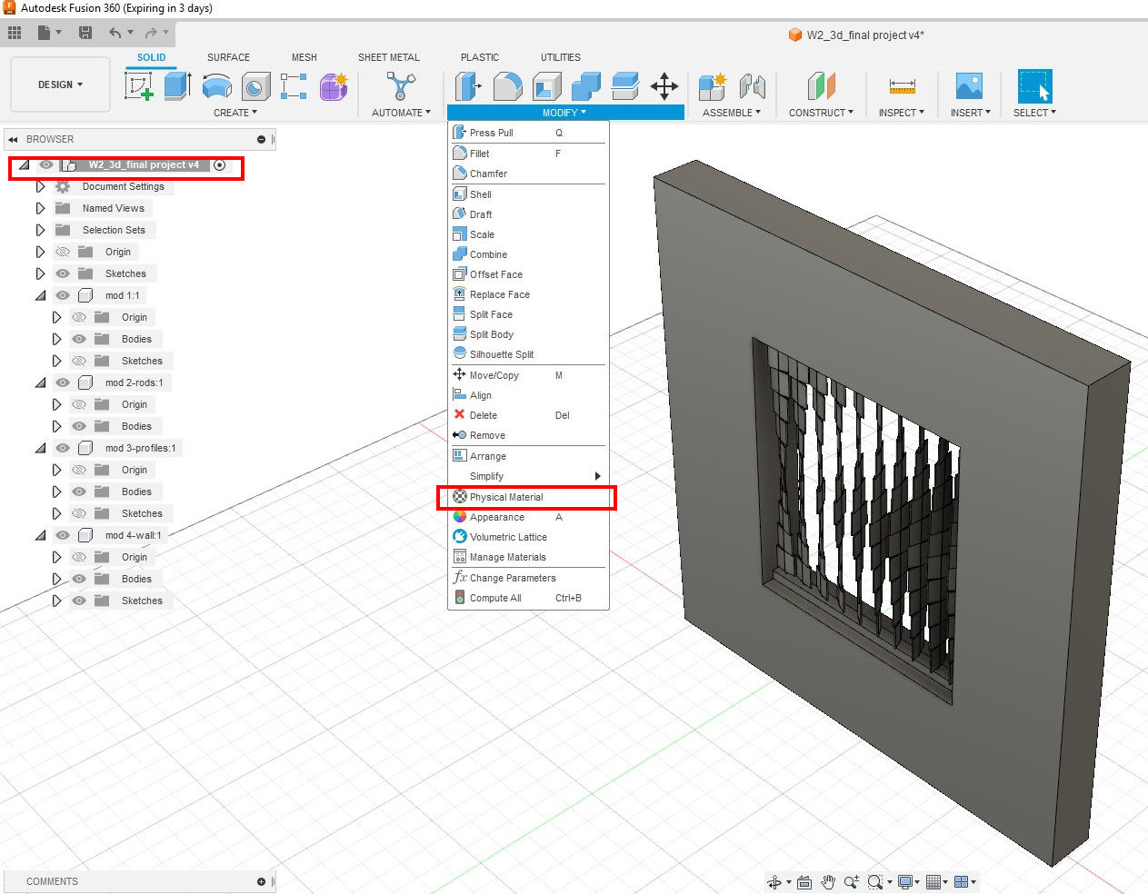
First I started sketching the profile of the module that will constitute by repetition the curtain in Fusion 360.
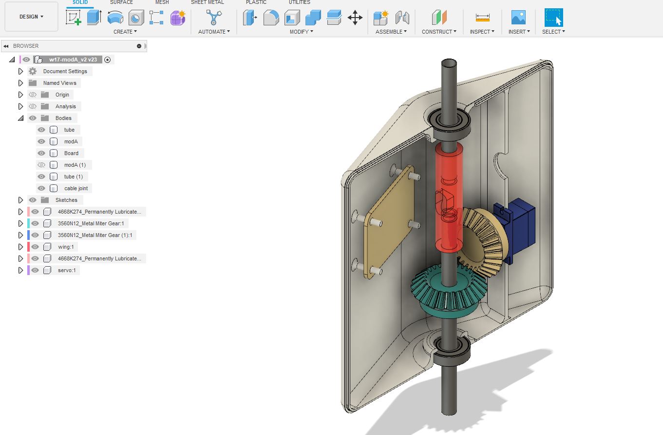
Then I extruded this first element and copied vertically to have the vertical module. I rotated the Module 1 for each copy 15 degrees, from one modeule to the other one.
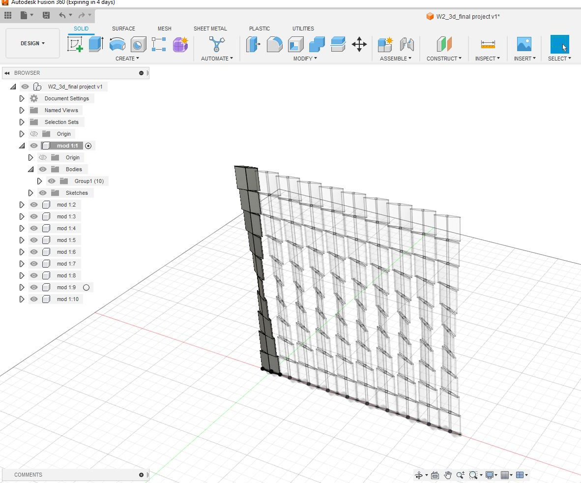
Each module in the Kinetic Curtain comprises a metal hollow tube at its core, serving as the axis for rotation. These tubes will be connected to top and bottom profiles, which will house and conceal the entire mechanism. The Kinetic Curtain will be mounted on a prefab structure.
2. Module's Mechanical Design
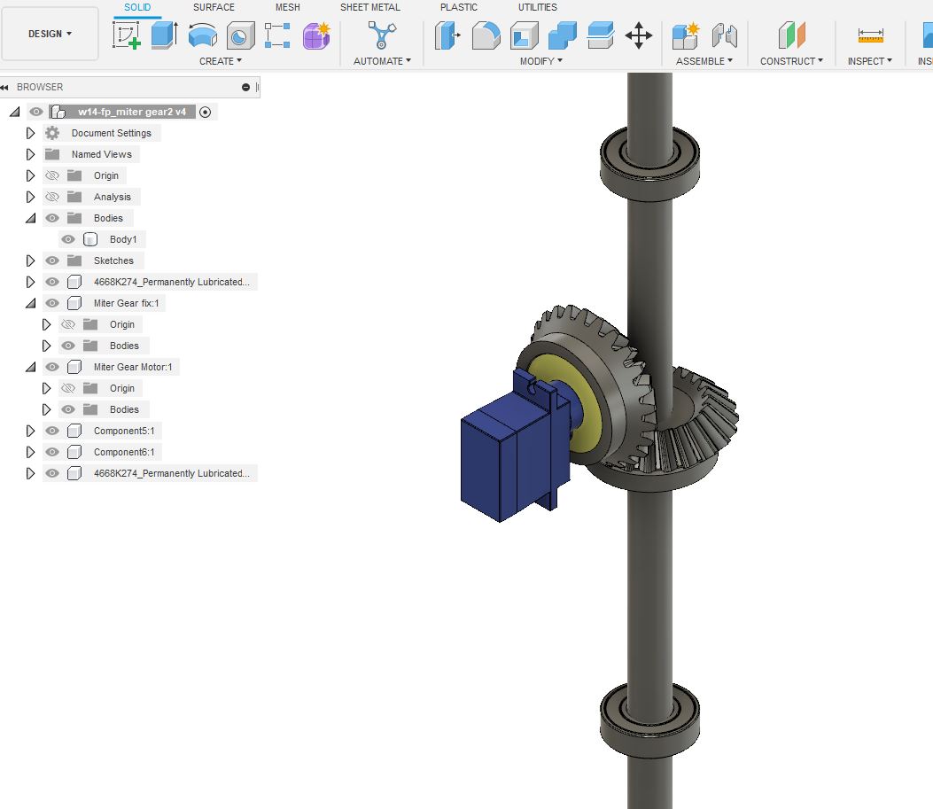
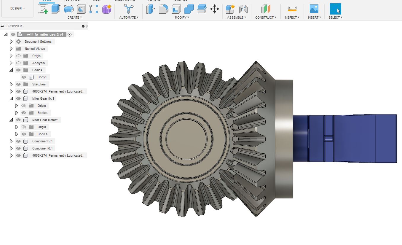
To design the rotation mechanism for the module, I initially considered using a servo motor that would rotate in parallel to a gear fixed at the shaft, which is the axis of the module's rotation.
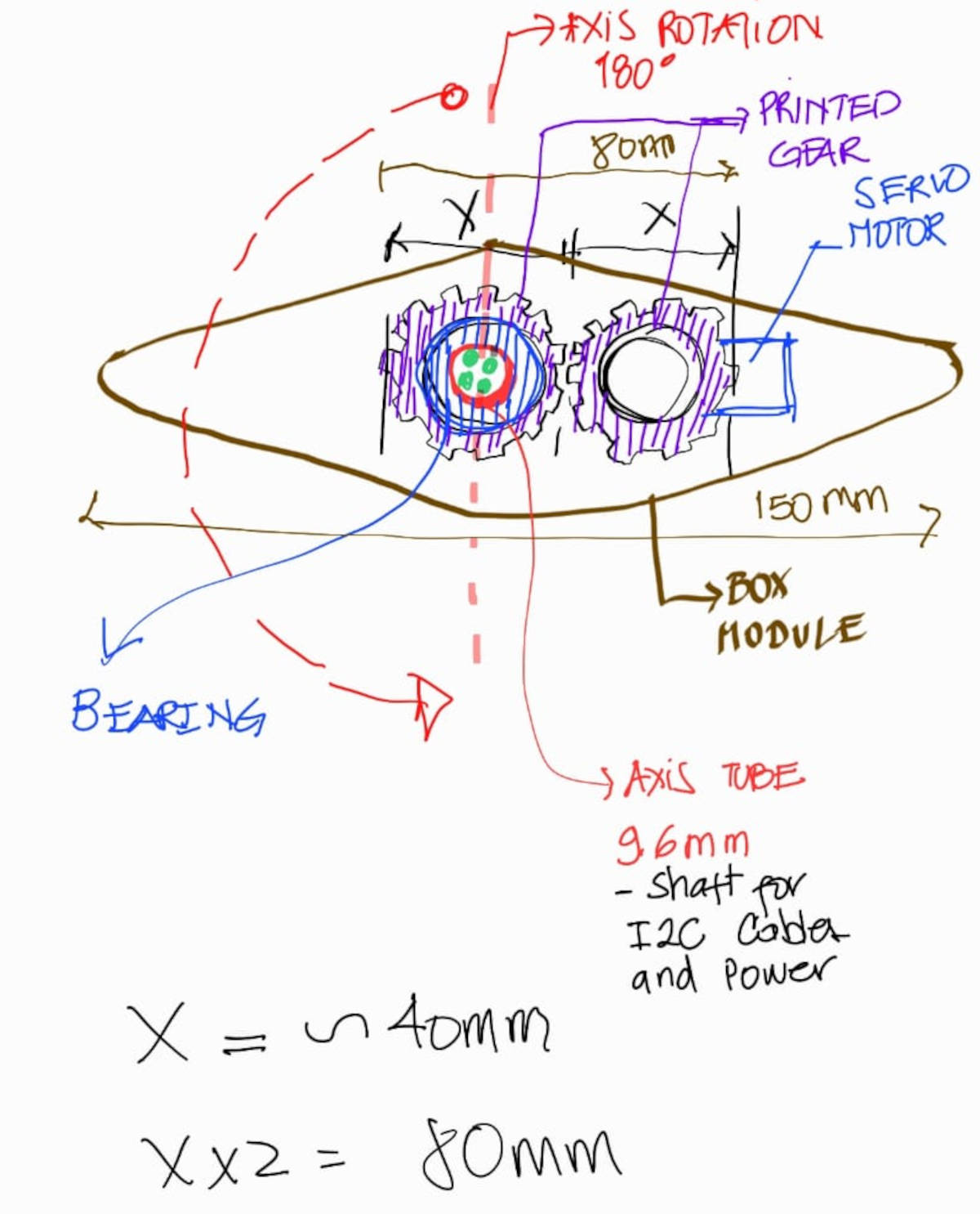
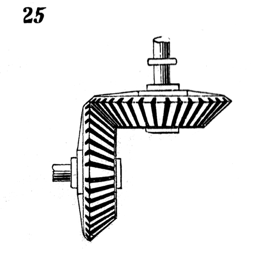
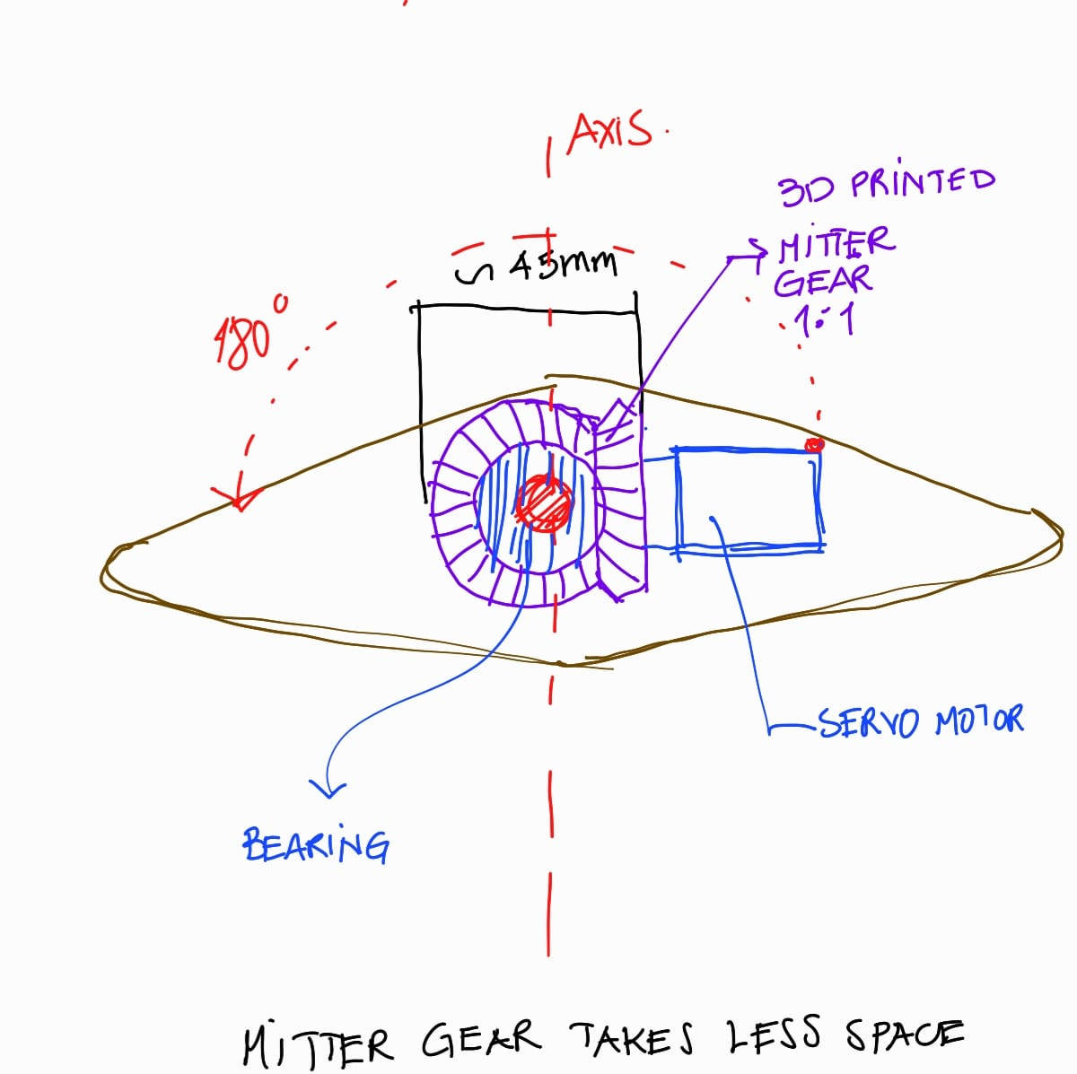
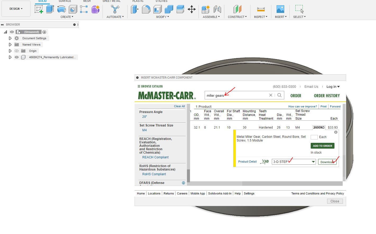
I am considering using bevel gears instead of parallel gears to make the module slimmer. Bevel gears change the axis of rotation, allowing for slimmer sides, and maintain the gear ratio. Bevel gears are oriented at a 90-degree angle, saving space. I will be using the same ratio of 1:1 with the same number of teeth. These are called MITER GEARS and they are useful for transmitting rotational motion at a 90-degree angle.
The Bevel Gears or Miter-Gears are one of the 507 mechanical movements.
Fusion 360 has a useful tool that can be accessed by going to Insert and selecting the tab for McMaster-Carr. This tool offers a wide range of mechanical parts that can be downloaded directly to the file as a 3D Step file. Once the component is in the file, it can be edited. There is a useful video available that explains how to do editing to components, ”HERE”.
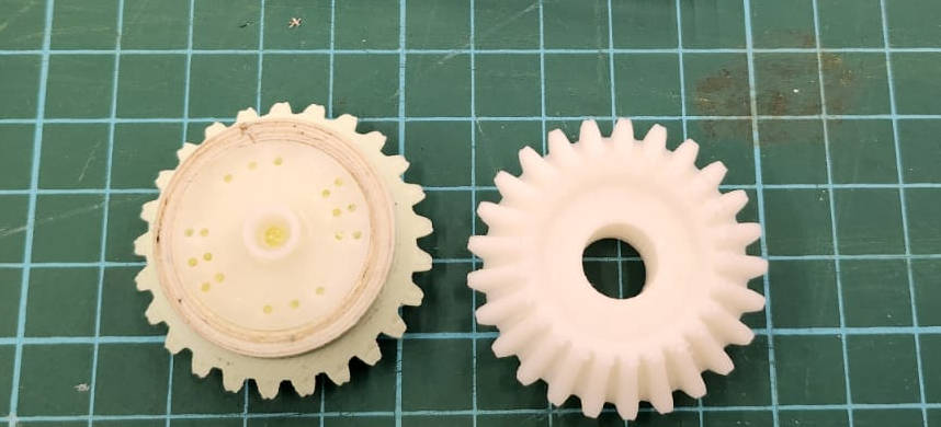
For the module design, I edited the gears so that the one fixed in the shaft can be connected to the other one that has space to insert the Servo motor round arm, saving space in the center module. By rotating the servo motor arm, the entire module rotates around the fixed shaft.
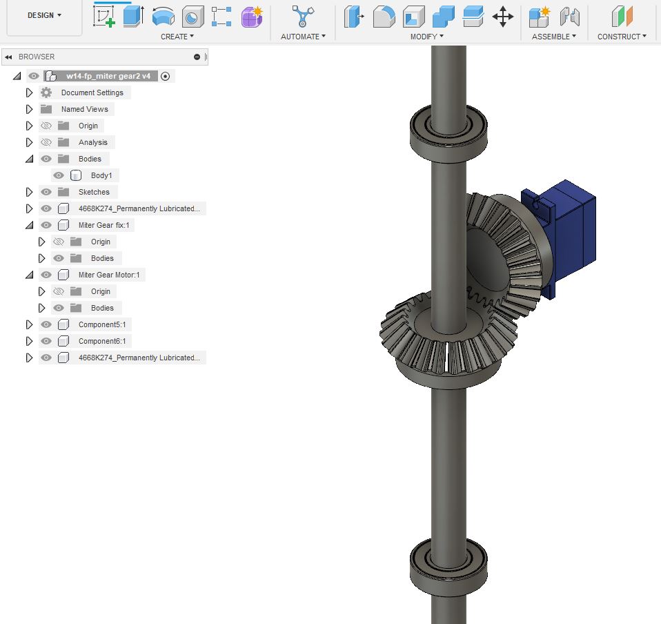
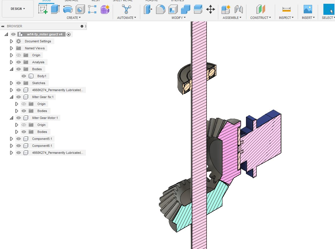
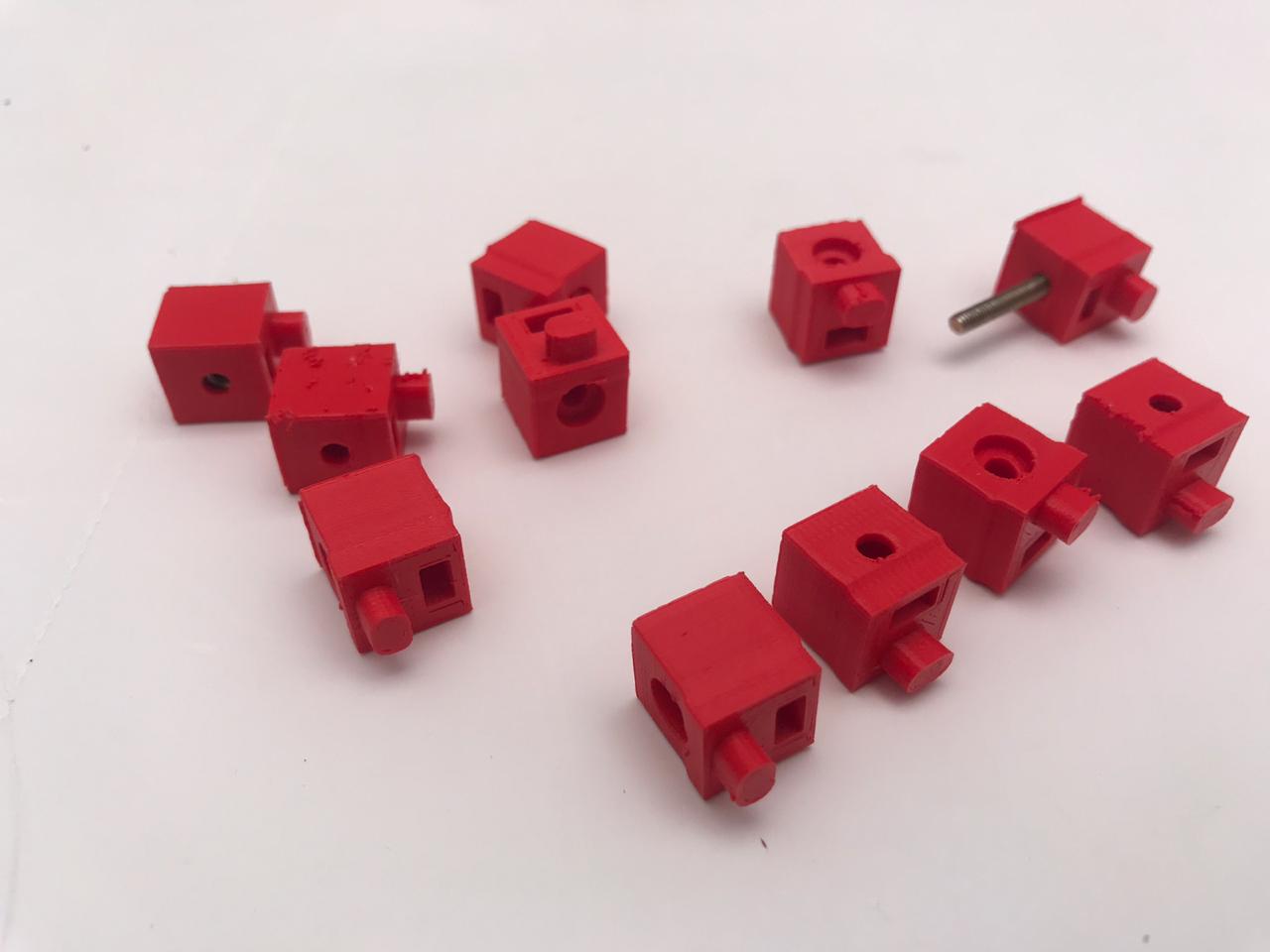
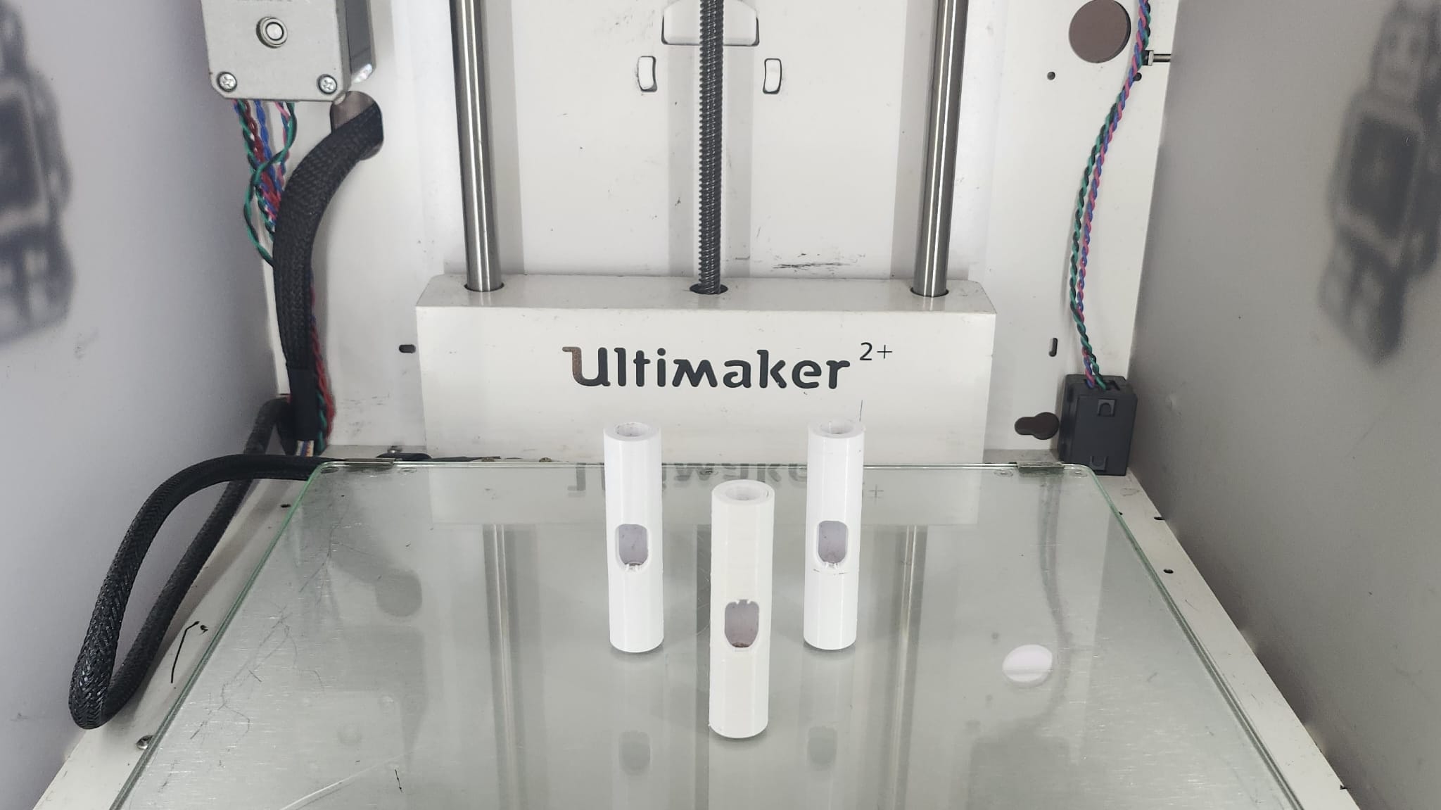
To facilitate the passage of cable wires, I have designed a connector specifically for the aluminum tubes. This connector not only accommodates the tubes but also features a central hole through which the cables can be threaded and connected to the Sub-board
3. 3D Printing the parts
I proceed to create the STL file for the Gears, see WEEK 5. 3D SCANNING AND PRINTING, for more details on how to create this file from Fusion 360.
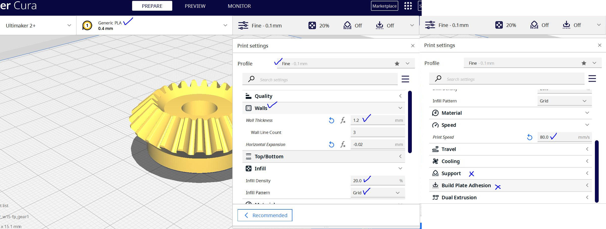
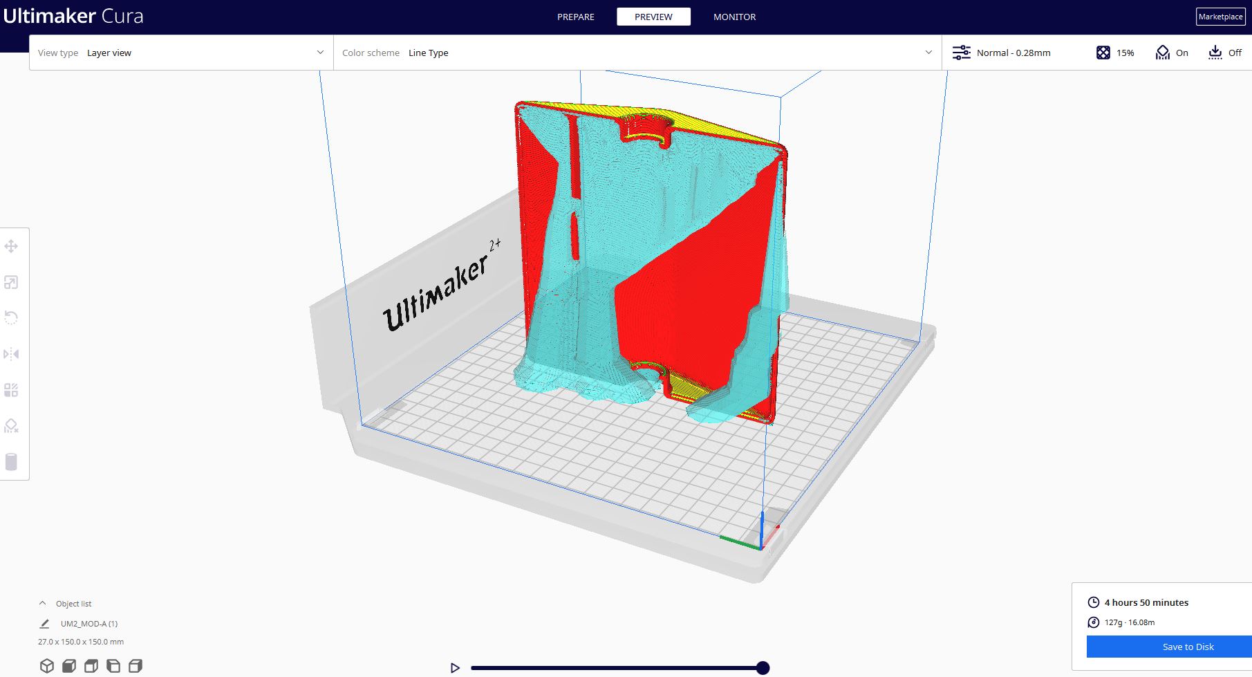
After obtaining the STL file, I opened it in the Ultimaker Cura program to slice the model for 3D printing. For the gears, I required greater precision in printing to ensure they could withstand the torque of module rotation, so I configured the settings to make them stronger.
- Generic PLA: 0.4mm
- Profile: fine
- Walls: 1.2mm
- Infill intensity: 20%
- Infill Pattern: Grid
- Speed: 80 mm/s
- Support: I didnt put it, but I should've for one of the Gears.
Then I proceeded to slice the model and generate the G-code to send to the 3D printer, I made the same process to both gears.
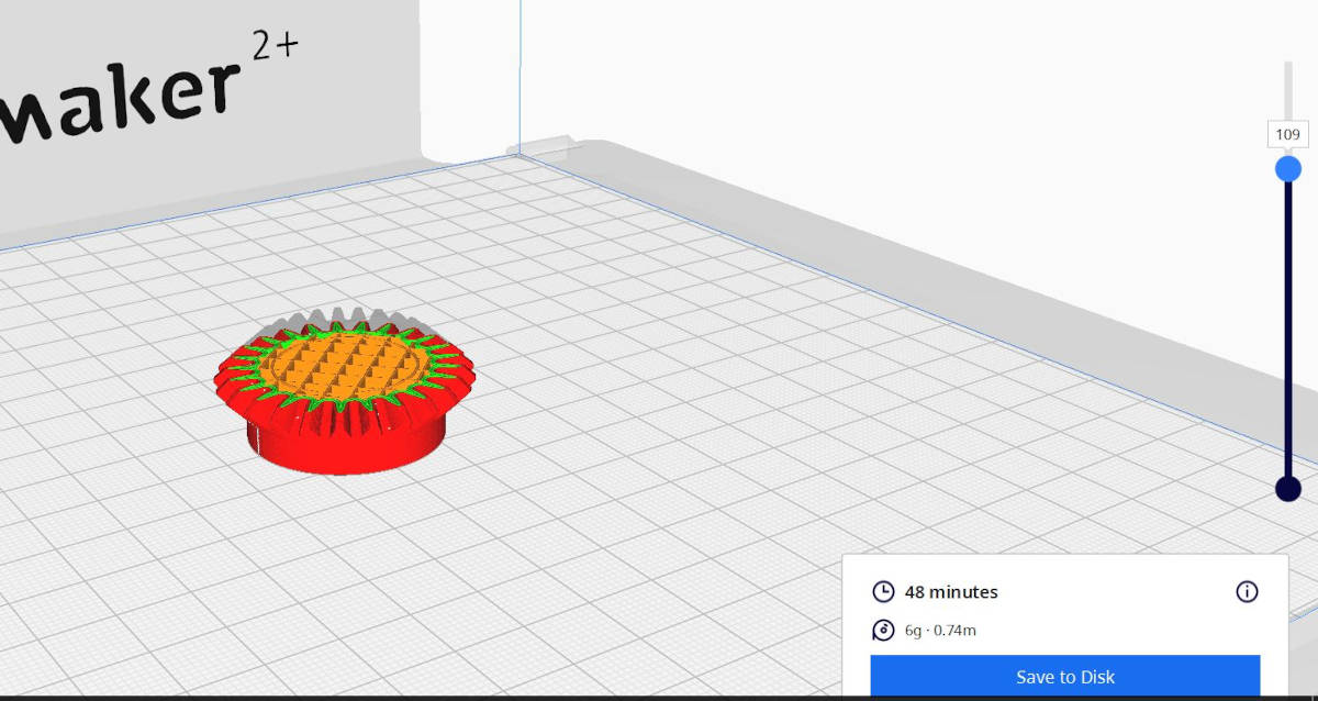
There were a few issues with the gears. For example, the shaft for the fix gear was too loose. Also, I should have added 3D printing support to the other gear where the servo wing is supposed to fit, which caused a not-so-neat finish. Unfortunately, I lost the photo showing this, but I was able to fix the issue with the gear and servo wing for the first module rotation test.
I used the same setting to 3D print the connectors
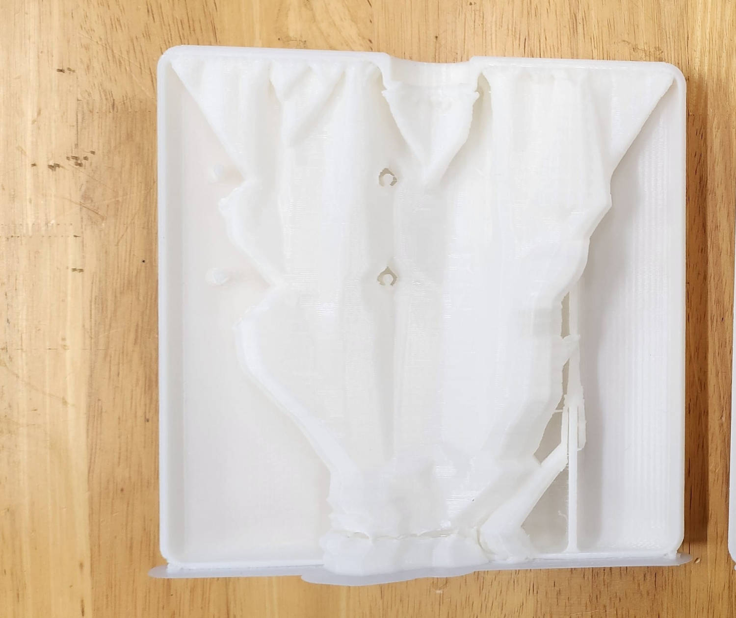
For the Modules case I used different Print settings as it could take long to 3D Print and it needed support.
- Generic PLA: 0.4mm
- Profile: Normal
- Walls: 1.2mm
- Infill intensity: 15%
- Infill Pattern: Grid
- Speed: 65 mm/s
- Support: Tree 5%
|
|
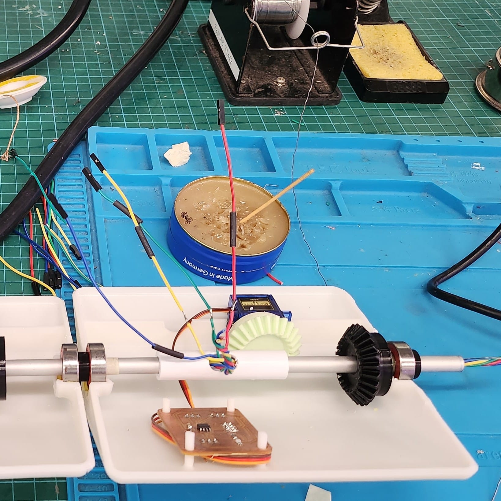
4. Module Mechanics test
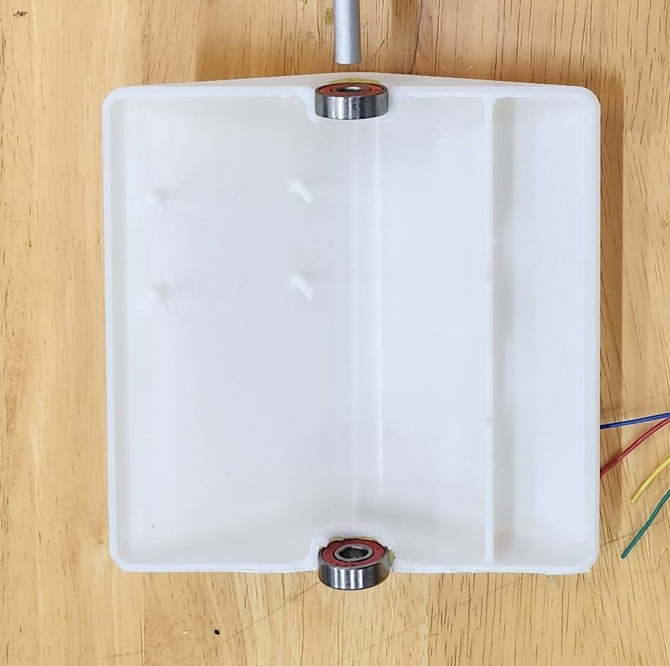
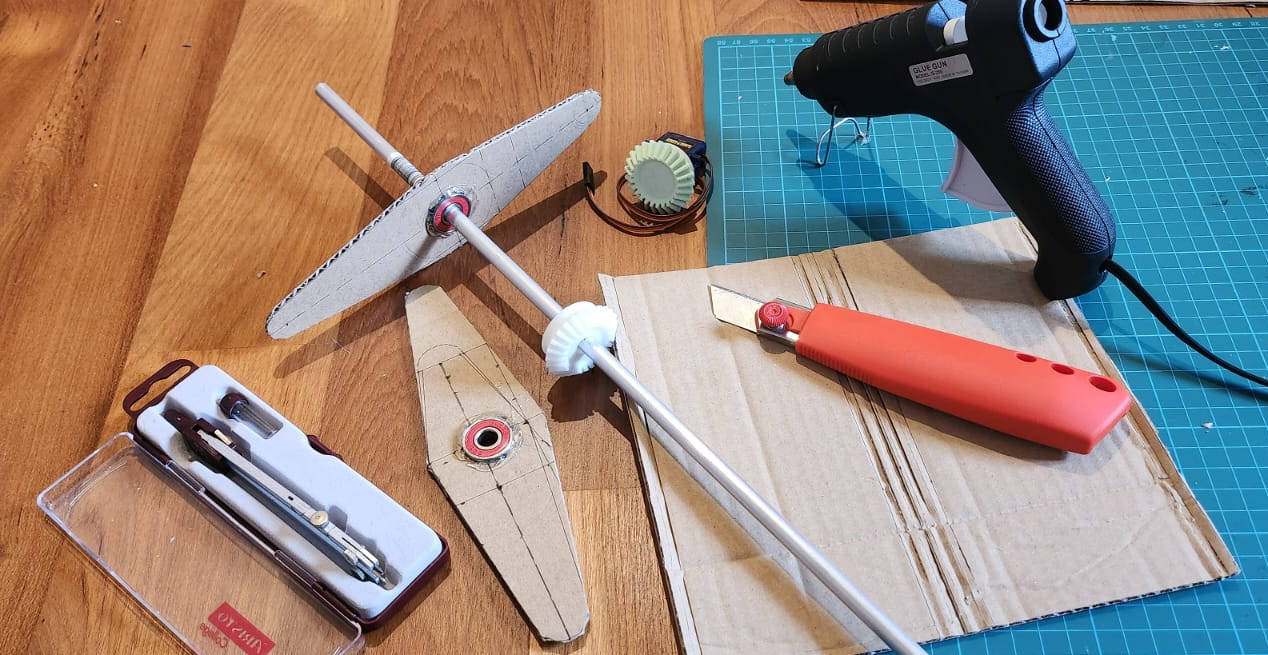
As soon as I have the gears 3D Printed, I conducted a test for the project. Unfortunately, I didn't have enough time during the week to laser cut the cardboard for the module, so I opted for an analog approach instead. I used a pen and a compass to trace out the design on the cardboard, then cut it out with a utility knife and put it together with Hot glue. Although it was a manual process, it allowed me to save time and proceed with the mechanical testing of Module.
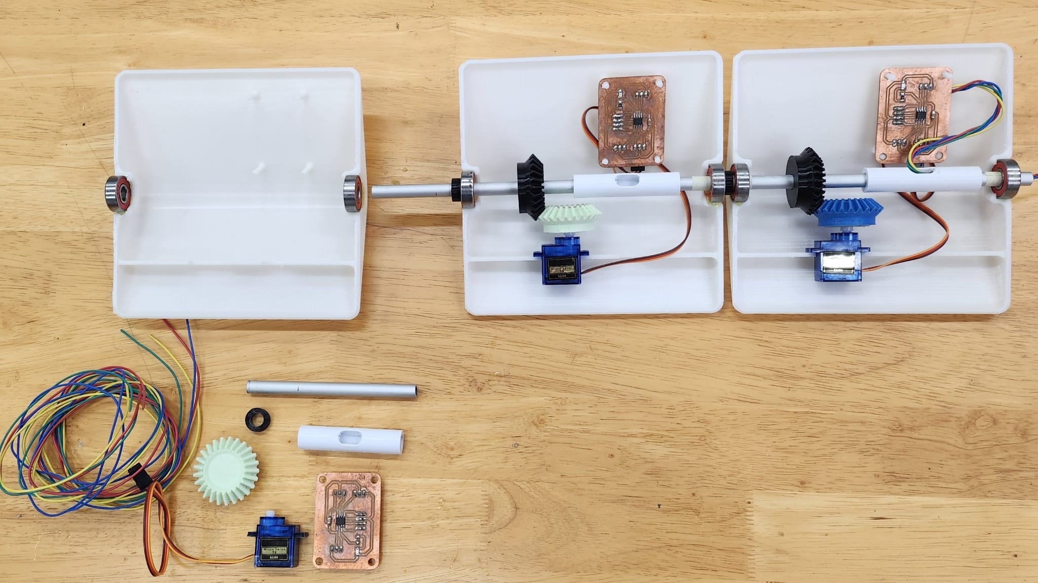
-The materials of the Mock up Module are:
- (1) Aluminium Round pipe, outer diameter 10mm
- (2) Ball bearing, 10mm shaft. 21mm diameter
- (1) 3D printed fix Bevel Gear with shaft of 10mm
- (1) 3D printed Bevel Gear with space for the Servo motor Arm
- (1) Servo motor SG90
- (1) PCB in this case I used the XIAO from week 8, for testing. For the final project I will be using ATtiny 412 in a I2C Bus connection
- (3) Jumper cables to connect the servo motor to the PCB
- (1) Potentiometer to control de angle of the Servo Motor movement, just for testins, the final project will have the angle movement Programmed
- Module case, still under design, and material to be selected. Options: Cardboard or 3D printed
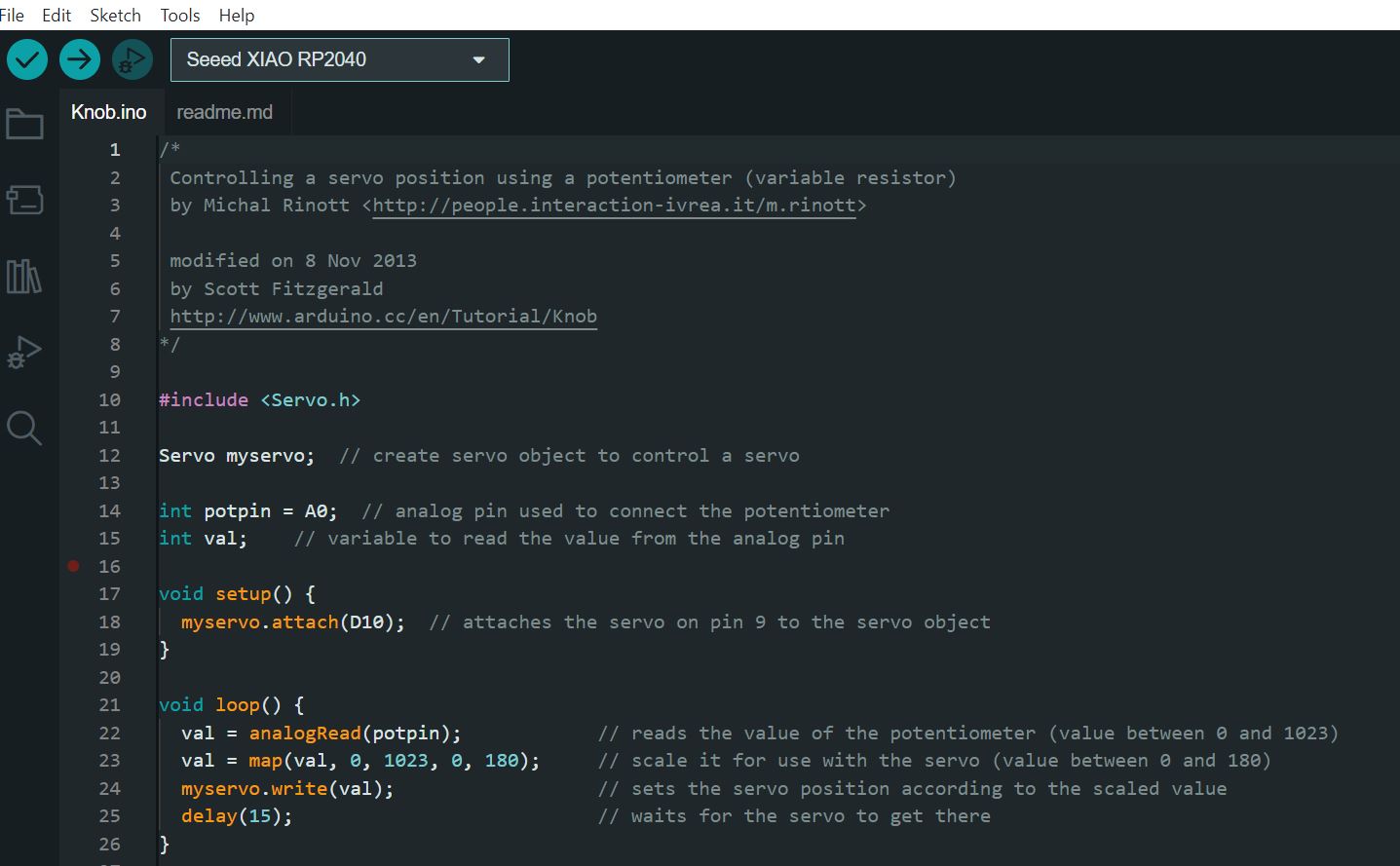
For the testing I used my XIAO RP 2040 Board and a Potentiometer to control the Motor movement and used the following Arduino Code for it:
ELECTRONICS
1. Design and Making of Main Board
As previously noted I ended up making some changes to the original proposal. Initially, the plan was to use a Bluetooth system to communicate with the Sub-Boards, but I decided to go with an I2C system instead. As a result, wires will be used to connect each component to the main board.
The reason for this change is that I wanted to use cable power to supply each module with electricity, rather than relying on batteries. This approach makes it easier to repeat the modules over a longer distance, potentially spanning hundreds of them. It wouldn't be practical to power each module using batteries alone. By running power cables to the modules, I can also run data cables.
What I need to design the Main Board:
- I2C Bus connection: To connect and comunicate with all the sub-Boards.
- Bluetooth connection: To control the preset setting to move the modules.
- Light sensor connection: To measure the quantity of light for the programming of settings according to the amount of light received.
- UPDI: To Upload the programs into the Board.
- Microcontroller: The brain of the Board.
-I2C Bus connection
The I2C protocol is a ”SERIAL COMUNICATION” that is bidirectional between a mainboard (master) and sub-boards (slaves). The sub-boards are only allowed to transmit data when they are addressed by the mainboard. This communication takes place through a binary unit system (BUS) that transmits data across the network. See this ”LINK” for more details.
Physically the Bus needs four wires. The SCL which is the Clock Line, its purpose is to coordinate and harmonize the transfer of all data across the I2C bus. An SDA line, is the data line. The SCL and SDA lines should be connected to 5V and GND lines, these lines go to all the Sub-Modules.
These two lines are an ”OPEN DRAIN” driver (a concept I still don't understant), which means the chip can drive its output low, but it cannot drive it high. For the line to be able to go high I must provide pull-up resistors to the 5v supply. There should be a resistor from the SCL line to the 5v line and another from the SDA line to the 5v line. You only need one set of pull-up resistors for the whole I2C bus, not for each device, as illustrated below:
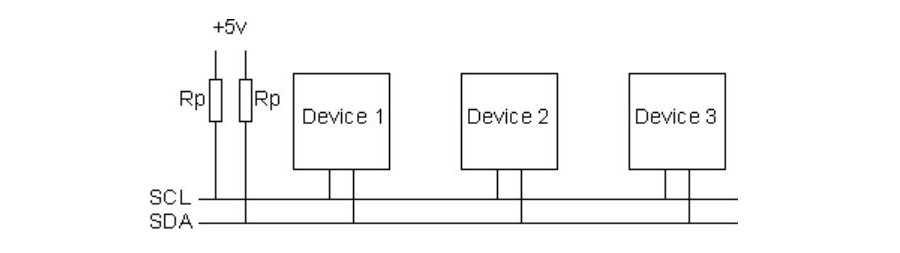
I2C Bus Schematic by www.robot-electronics.co.uk
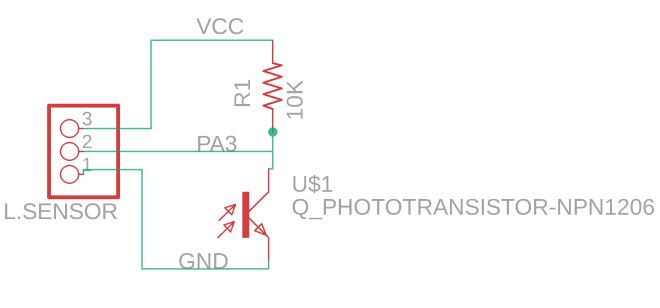
-Light Sensor Connection
One of the purposes of the "Kinetic Curtain” is to be responsive to light stimuli, As the amount of light increases, the modules of the curtain move closer together, effectively blocking direct light from entering the space. To acquire this we need to gather information from a Light sensor, called ” Phototransistor” it detects the light pulses and converts them into digital signal, the phototransistor is an input device.
When the light intensity is measured, the information is transmitted to the main board microcontroller. The microcontroller, that has been pre-programmed with specific instructions, then sends a signal through the I2C Bus connections to the sub-modules, directing them to close to a specific angle based on the light intensity. For the light measurement, I will utilize the PT15-21C/TR8 "Phototransistor" model, which needs to be connected to a 10K resistor, 5V, and GND.
Phototransistor Schematic by www.elprocus.com
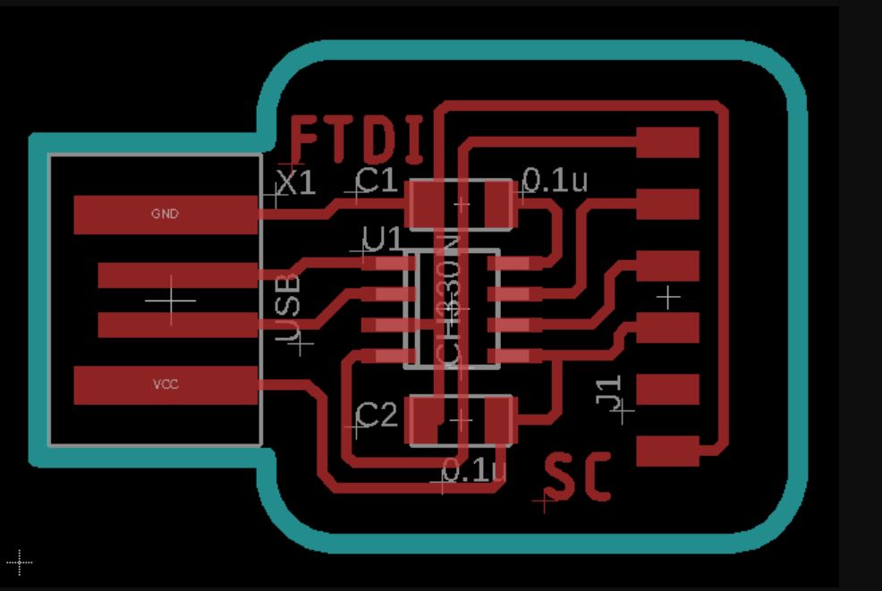
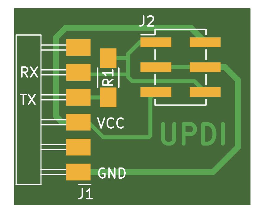
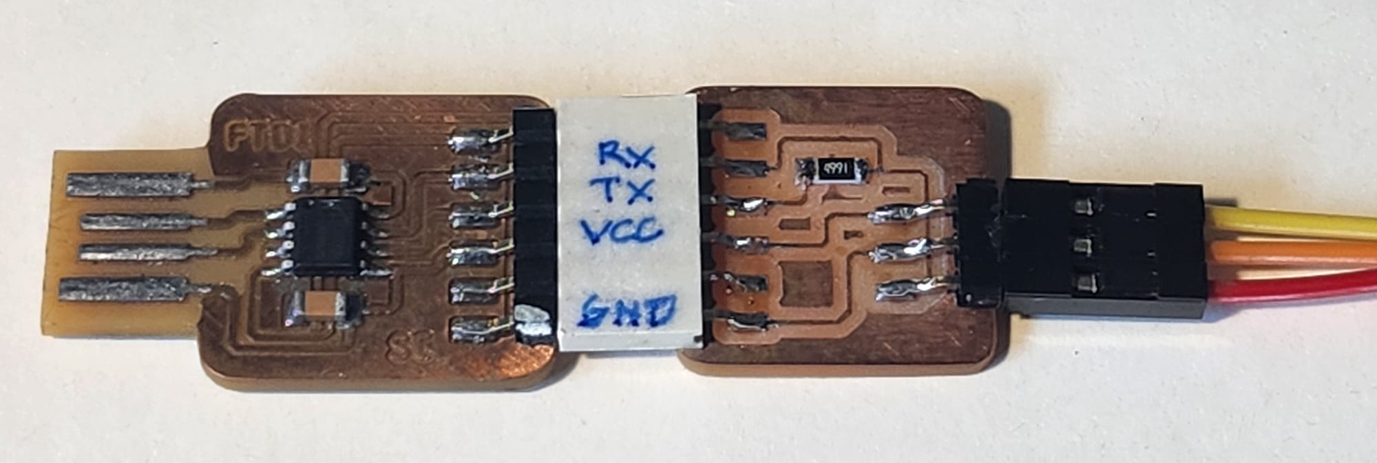
-UPDI (Unified Program and Debug Interface) and FTDI (programmer/debugger)
Since the ATTINY 412 Microcontroller that I am using for the main board has limited memory and no built-in boot loader, I must use a combination of a ”UPDI”, and an ” FTDI” to program it. This microcontroller has all the necessary I/O pins that I require so it is enough for the project.
|
|
With the templates found at the FabAcademy page, I milled the FTDI and UPDI boards. But after milling the boards and solder the necessary parts, the computer didn't recognize them. UPS!
Debugging the FTDI and UPDI
- I connected the set to another computer, and It didn't work.
- I connected my UPDI to an FTDI from our Instructor Steven, and it worked, so the UPDI was working but not the FTDI.
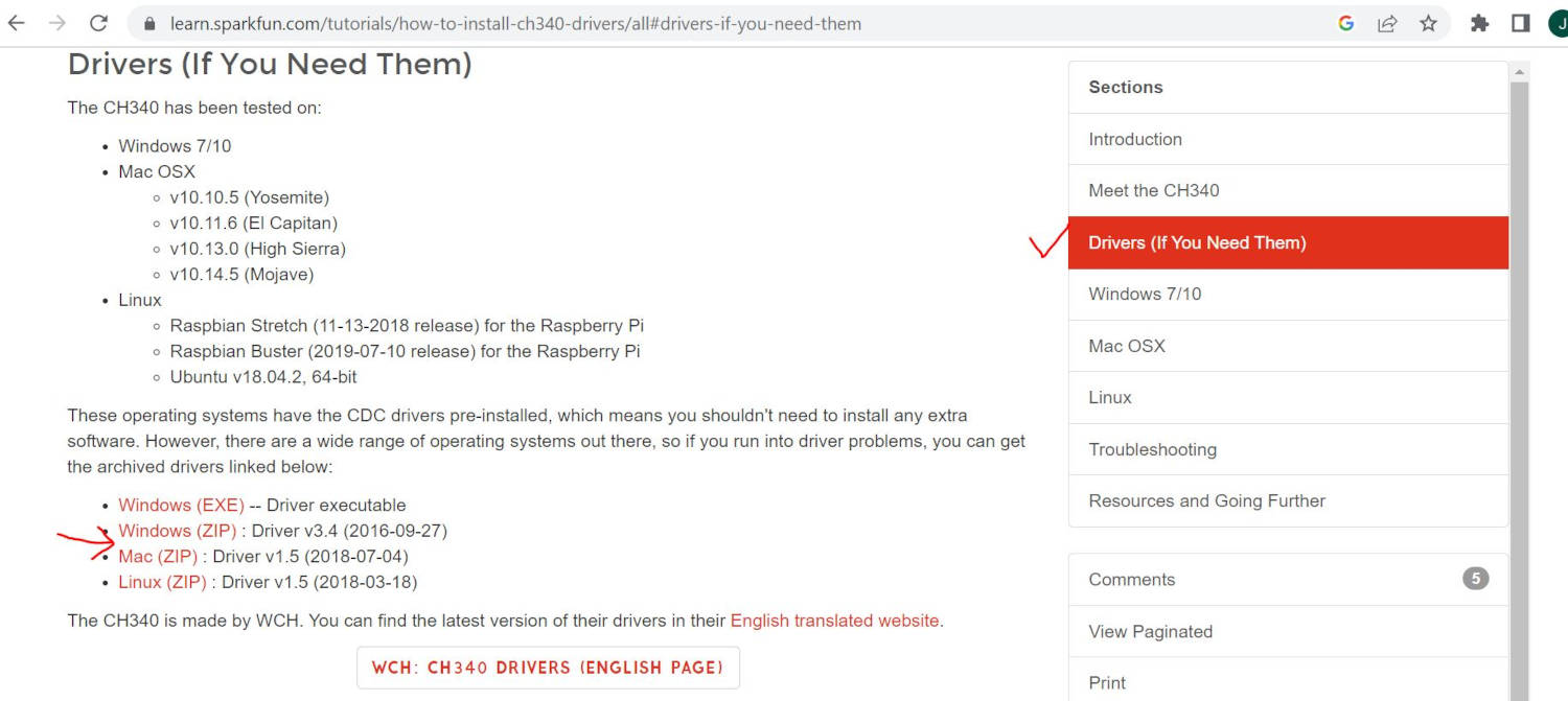
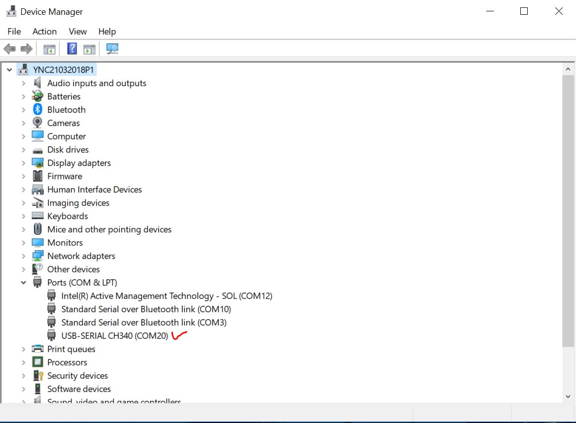
- I connected the working set to my computer and wasn't recognized as a port. That meant I have to install the Driver for Windows to recognize the CH340 Driver, I looked for it on the web. ” Spark Fun Electronics.com” have a free download.
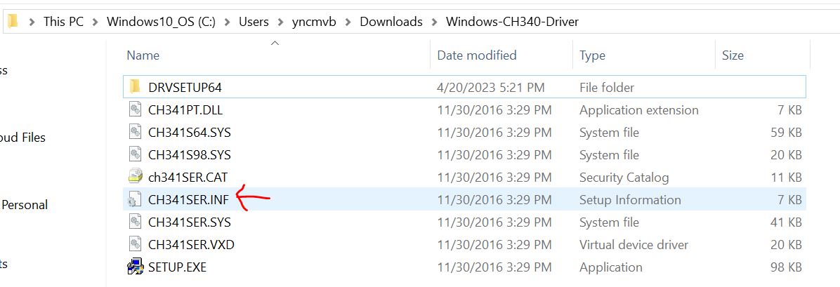
- Once the Drivers were unzipped, I executed the SETUP.EXE from the folder I downloaded, and the driver didn't work.
- Then I did right-click into the file: CH341SER.INF and chose to install and this time worked!
- The USB Serial CH340 Port was recognized by my computer!
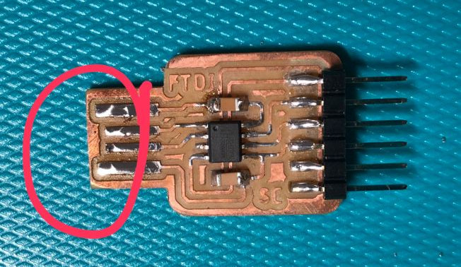
- Still my FTDI was not be recognized by the computer, and it was becuase the USB connection had the copper in front of it, I didnt know that it will create a bad conection. So I had to remove it.
- Problem solved, the computer recognized the set of FTDI and UPDI. To be fair, Steven was next to me guiding me on how to fix these problems, I didn’t have any idea how to solve it by myself.
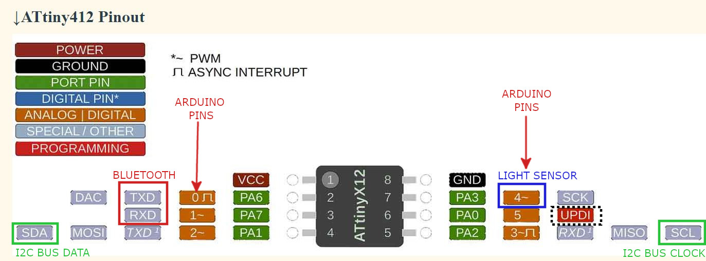
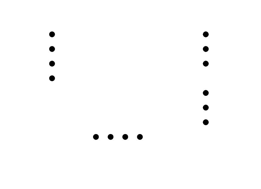
-ATtiny 412 Microcontroller Pin out
The ATtiny412 has a total of 8 Pins. The manufacturer has already assigned functions to some of these pins, but they are enough for me to connect the devices I need. As I will program in Arduino I have to follow the secuence of number colored orange, Pin 0 to 5, VCC and GND are common for all programs.
- Pin 0=TX
- Pin 1=RX
- Pin 2=SDA (I2C BUS Data)
- Pin 3=SCL (I2C BUS Clock)
- Pin 4=LIGHT SENSOR
- Pin 5=UPDI
- VCC
- GND
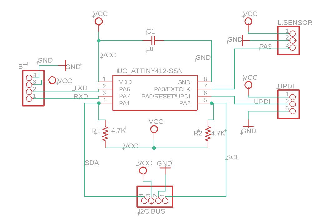
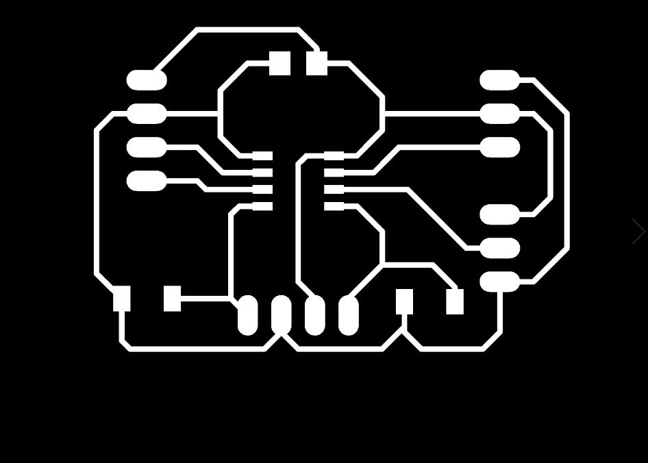
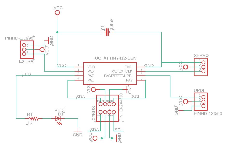
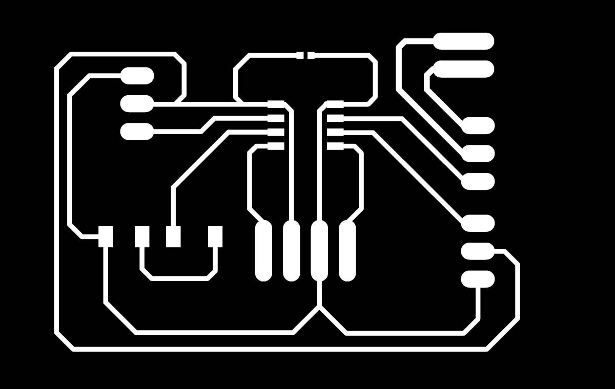
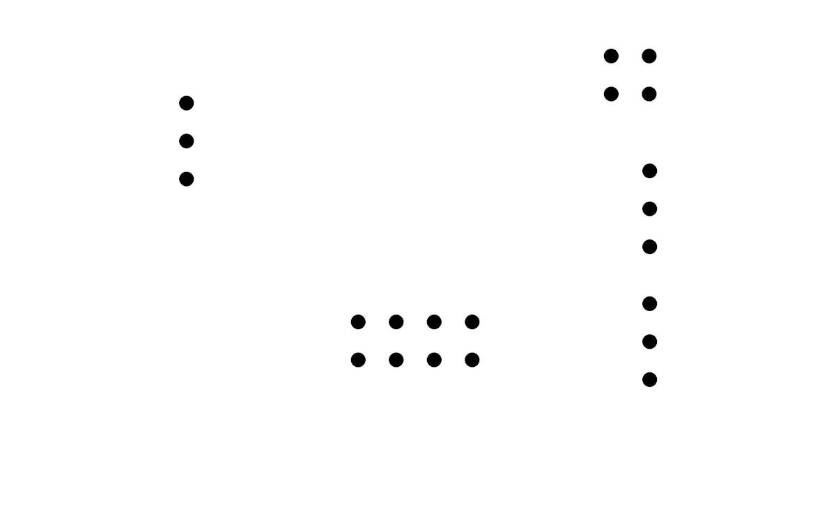
-Main Board and Photosensor Board in Eagle
I used Eagle in Fusion 360 to make the schematic and the Board taking all the information I gathered until now. But as the light sensor should be next to the "Curtains" modules I mage a separate PCB to connect the sensor, this board wirll be connected with wires to the Main Board.
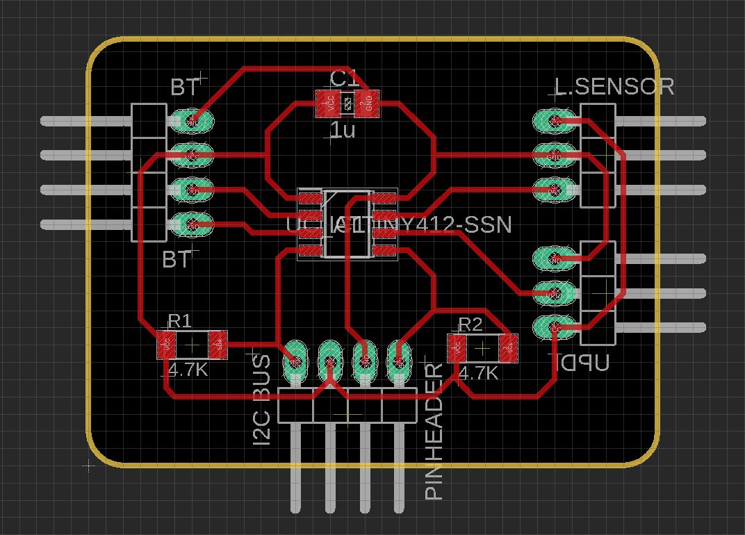
Main Board:
|
|
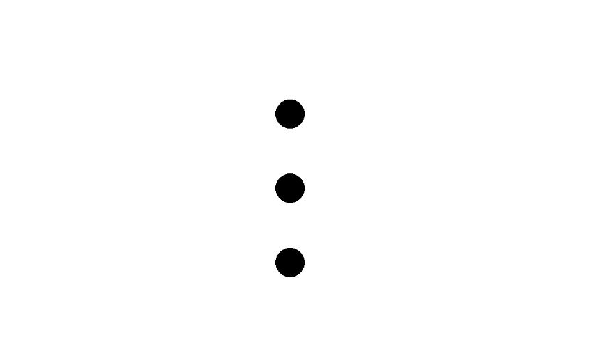
Light Sensor Board:
|
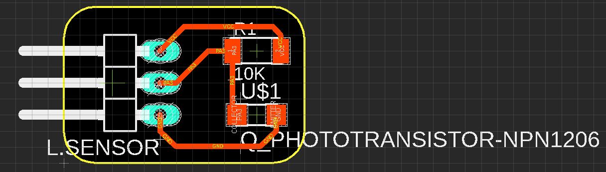
|
Then I exported and edited the PNG files to send to Mods, for both PCB’s
|
|

|

|
|

|
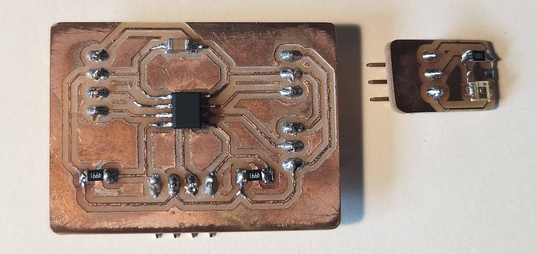
Here are the two PCB's milled with all the components soldered in.
-Testing the Main Board
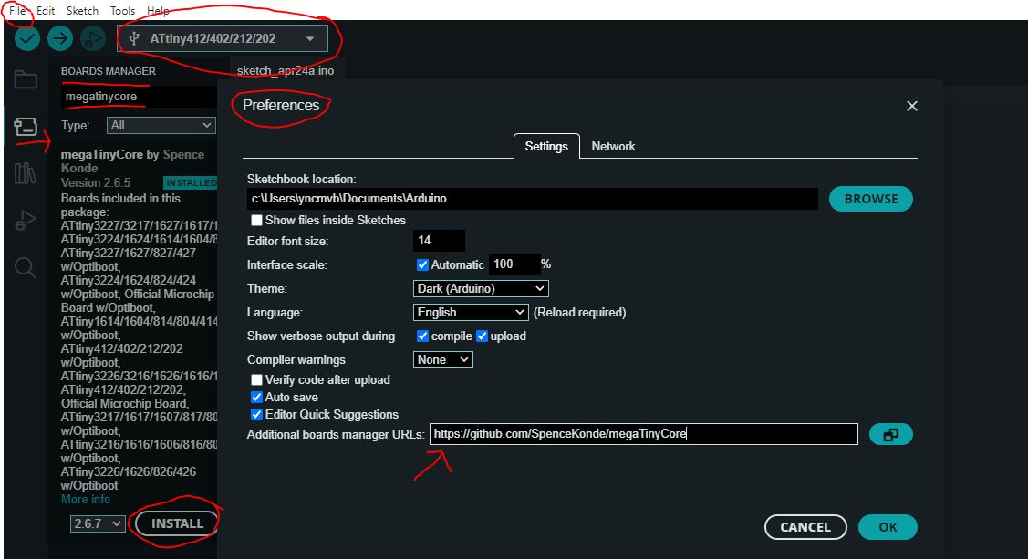
Before uploading the sketch into the Main Board, I had to Install in the Arduino Program the ATtiny 412 Board. For it, I opened Arduino, and had to go to File> Preferences> and when the window is open paste the this ”MegaTiny Core Link ” into the Boards Manager URL’s.
Then at the boards manager on the left we open the window and look for the Megatinycore and click in "select" to install the board package. Lastly select the ATtiny412 form the Tools> Board and the port number where the "UPDI" is connected.
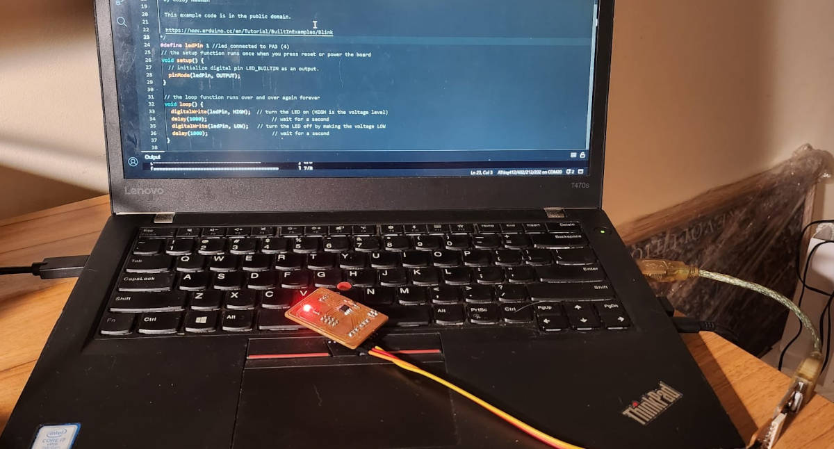
Once the Board and the port are selected, I proceed with the testing. I run the Arduino File> Examples> 0.1Basics> Blink.
This sketch allows me to test whether the Main Board is functioning properly by checking if it is receiving both data and power, and if it can successfully transmit them to Output devices. In this particular case, the Output device is a LED light.
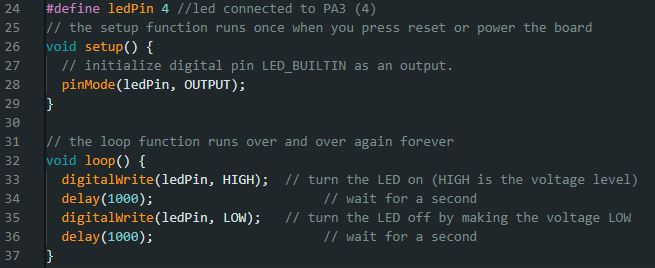
I uploaded the code to the board, and it worked, the light blinked.
-Light sensor testing
The light Sensor is an input device that measures the quantity of light as previously mentioned, this week I managed to test the sensor and the sensor miniboard. For it I uploaded a Code to read the quantity of light, and to write if the ambient was dark or bright. Unfortunatelly the code didn't work, but I could see that the sensor and the board were having contact, I have to work further in the programing of it. For further details refer to W12.Input devices.
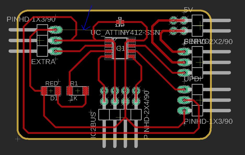
2. Peripheral PCB design
For this board, the microcontroller is again the ATtiny 412 and its available pin outs. I used pins for the UPDI to be programmed, In and Out I2C BUS network connection, an inbuilt LED light to test the board, and the Servo motor pin outs. I also provided two options for powering the servo motors: one directly from the board using 3V, and another option in case there's not enough power, which is a direct connection with 5V.
This option is for the motor servo be powered direclty from the board:
This option is for the motor servo be powered from an external 5V:
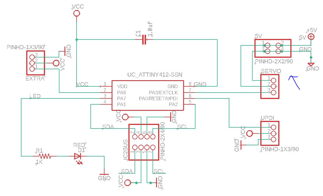
These are respectevly the PCB design boards:
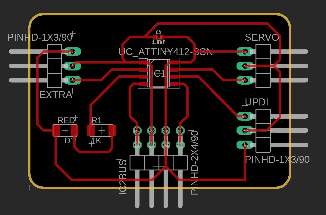
|
|
The PCB board with an external power connection has a separate ground, but the program considers the ground as a common ground for everything inside the board. As a result, an error message appears stating that the ground is not connected, even though it is connected to 5V, but that is not a problem as it is intended.
Then we do the same procedure as the previous boards, we generate the PNG files of the boards, retouch them in GIMP and then proceed to Mods to generate the G-Code to mill the boards.
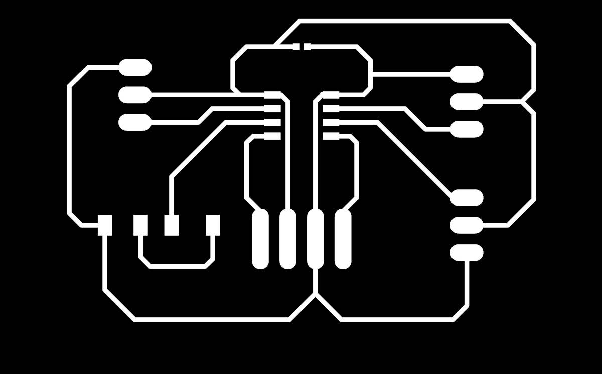
|
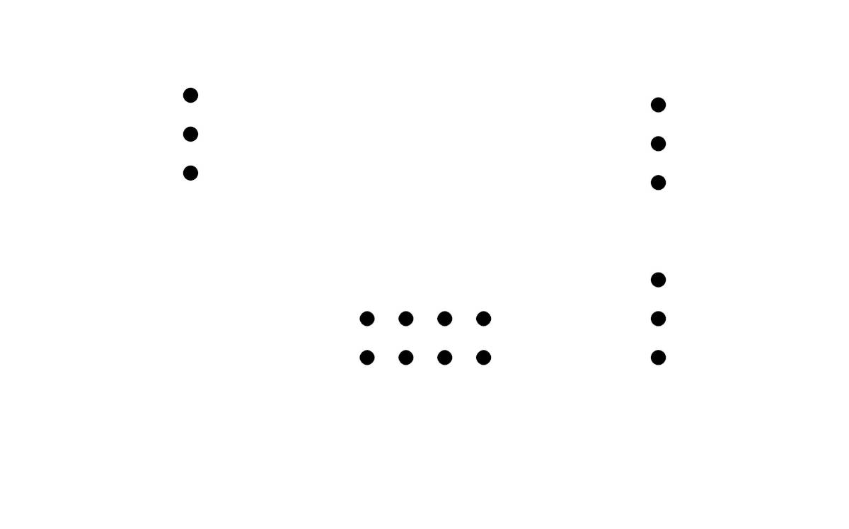
|

|
|
|

|
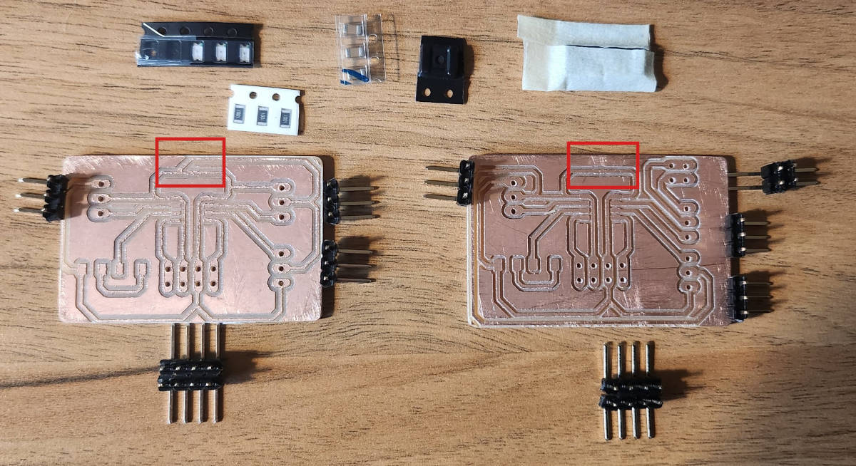
The boards are milled, now I am preparing for soldering and testing.

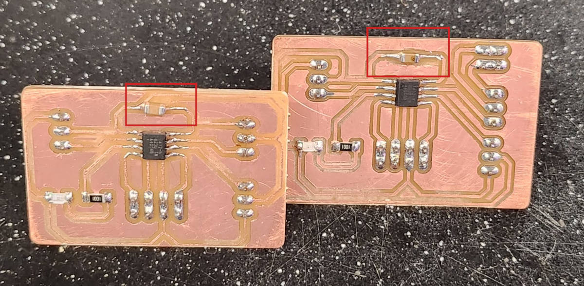
-Soldering the Perioheral Boards and testing them
After milling the sub-boards, I gathered the pieces for soldering. However, I noticed that the footprint of the capacitors was exceedingly small. To prevent soldering from reaching other areas, I had to cut away, with a utility knife, the excess copper around the capacitor location, restricting it to the intended traces.
Next, I used a multimeter to confirm that the paths had continuity and, more importantly, that the soldered components were not in contact with any other areas of the board. Everything appeared to be in order.
In the design of the Sub-boards I included an inbuilt LED light as I had spared Pin out and I could run the BLINK code easier to test the boards. So I connected the boards to the computer and uploaded the BLINK program and both of them responded. Next step is to connect the boards in a I2C protocol and move a servo motor, that requires another code.
PROGRAMMING
1. Connection between Boards via I2C Network
To establish communication between the two boards using the Serial I2C protocol, it is crucial to download the respective code separately onto each board, as covered in our learning materials during WEEK 14. NETWORKING AND COMMUNICATIONS.
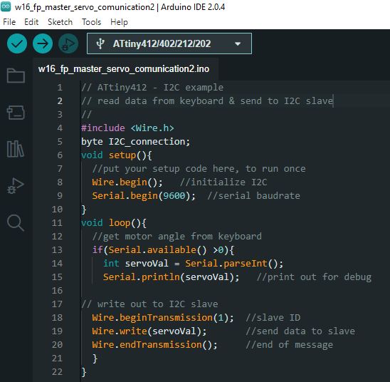
Main Board Code:
Sub-Board Code:
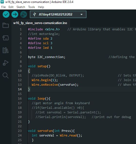
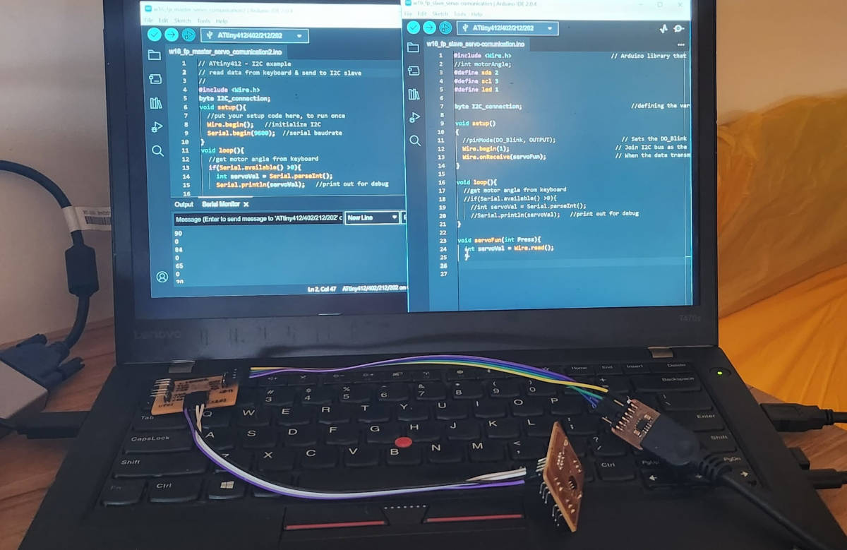
In this testing setup, we do not utilize outputs on input devices since we are directly testing the Serial communication (GND-VCC-SCL-SDA). In the following video, you will find the Main Board Code displayed on the left side and the Sub-Board Code on the right.
At the Serial communication window, when I write a number on the Main Board, the Sub-board receives this number. Following that, a number 0 is displayed, this is the Sub-board response. This code is designed to facilitate one-way communication, with messages transmitted from the Main Board and received by the Sub-Board.
Connections:
2. Understanding the Final Code
As noted previously In Week 15. Input Devices, when I made the board for the Photosensor, I ran a code to see the range of reading the sensor has, it was around 75 for the very bright light to 1023 for the darkness reading. With this value range, I established the way I wanted to move the modules.
I had clear that I wanted the panels to move in angles that will block or leave the light getting into the space according to the quantity of light, see the following table:
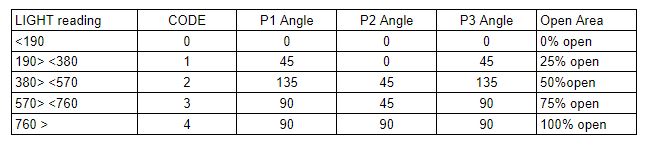
Based on the photosensor read with a range of 75-1023 giving us a total range of value of 948, I divide that by 5 and this gives us a value range of 190.
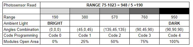
Here is the breakdown of the range and corresponding values:
- Range: 190, 380, 570, 760, 950
- Ambient Light: BRIGHT to DARK
- Angles Combination: (0,0,0) (45,0,45) (135,45,135) (90,45,90) (90,90,90)
- Code Programming: 0, 1, 2, 3, 4
- Modules Open Area: 0%, 25%, 50%, 75%, 100%
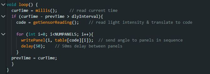
In the programming, we employ a table to assign positions to the modules. Each position in the table is linked to a specific code that the program reads and converts into three values enclosed in brackets. These resultant values represent the respective angles of movement for module 1, module 2, and module 3. Subsequently, these angle values are transmitted to the peripheral boards.
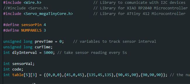
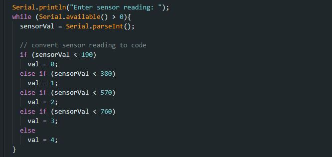
However, it is necessary to provide instructions to the program to convert the values received from the photosensor. These values need to be translated into the appropriate codes, which will then be converted into the specific angles as specified in the aforementioned table.
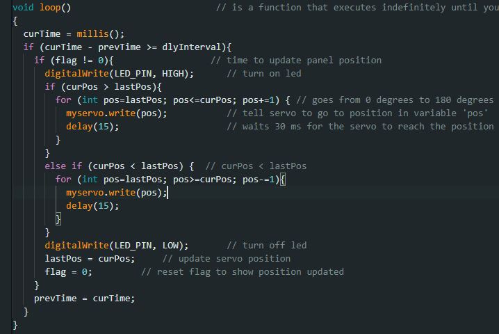
In the program, specifically within the Void Loop section, there is a code that guarantees the sequential transmission of angles to each board.
Before sending the code to the panels, Steven had the idea to perform a test using the Serial monitor. He wrote a value called "reading" and checked if the program correctly interpreted it as an angle position.
It is possible to see in the following video how I write a value and the program translates it into the paneling position. First I write 80 and then it says the position is 0,0,0, then I write 360 and it says the panel position is 45,0,45, and so on.
3. Final Code
Once we tested the code in the serial monitor, Steven helped me to modify the Main Board code, so this time instead of sending the information to the Monitor, the information will be sent via I2C protocol to the Peripheral Boards inside the modules.
ASSEMPBLY AND TESTING
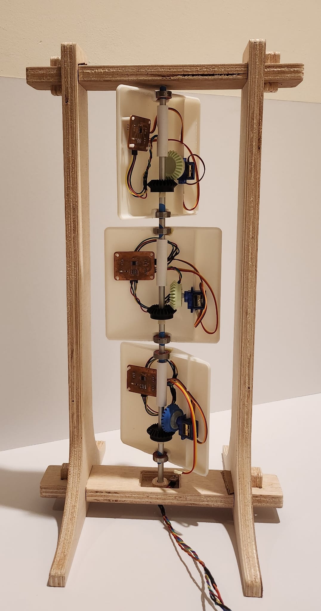
To assemble the modules, I needed a structure that could hold the three modules together. I really liked the project from Week 7 because it had modules that could be assembled using "Tusk Tenon Joints," which made it easy to take them apart when needed.I used Fusion 360 to design this structure and its parts.
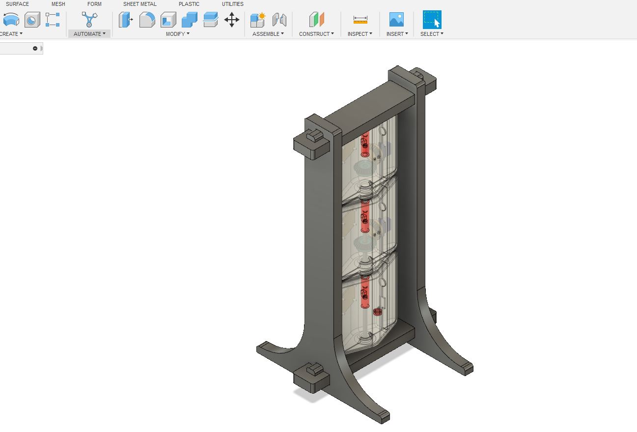
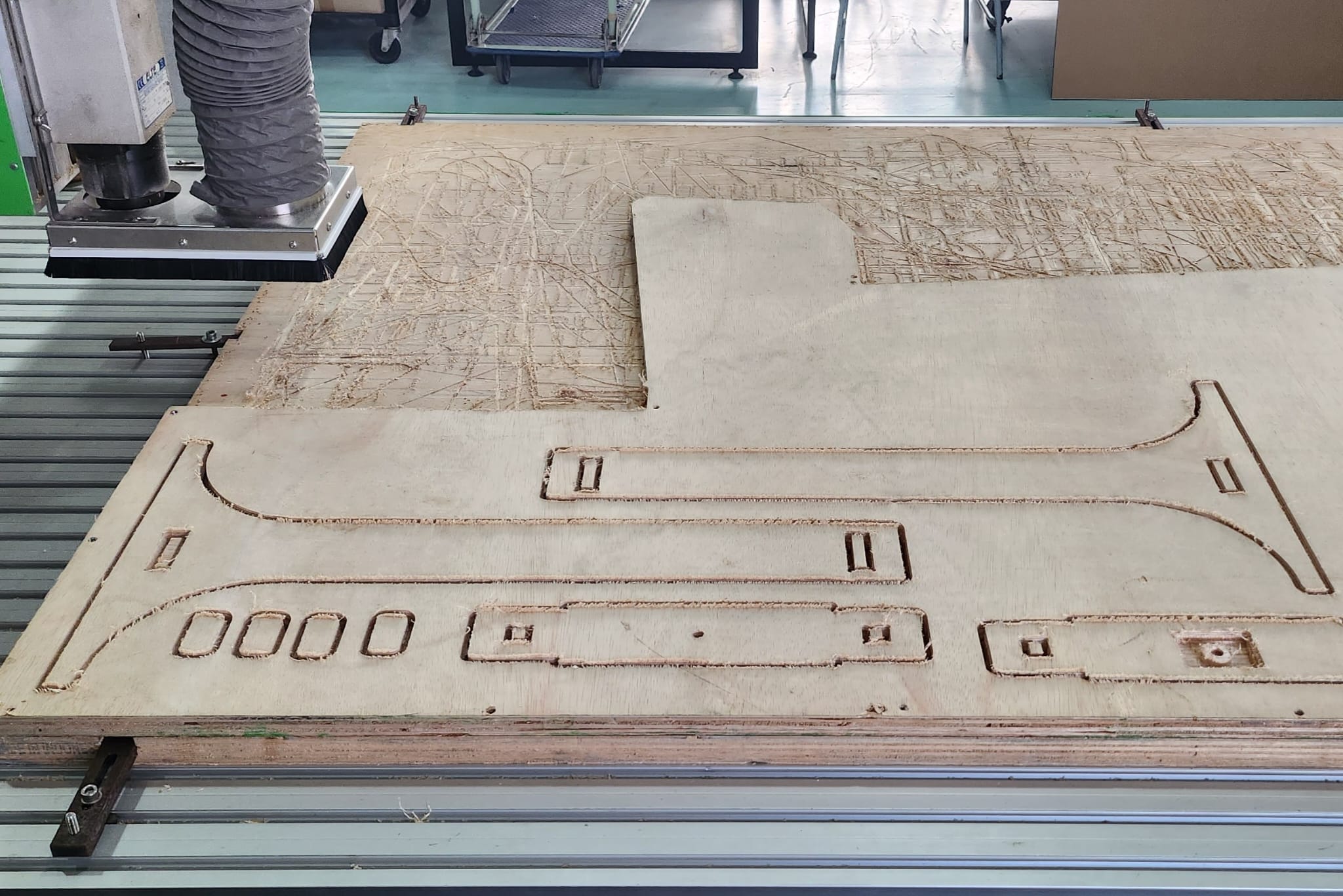
Afterwards, I milled the parts using the CNC machine and sanded and assembled them.
I put all the modules parts together and started to assemble them too.
I had to solder all the cable joints and make sure the connections were tidy to avoid a tangled mess of cables. To achieve this, I passed the cables through each 3D printed joint, which would later be connected to the peripheral boards. And then I checked with the multimeter that all the connections had continuity.
This is the prototypes mounted in the structure
This is the moment I have waited for: Testing the System
I have made a general BOM (Bill of materials) on WEEK 17. APPLICATIONS AND IMPLICATIONS, and the cost came around $100 Singaporean Dollars, fro the three modules and its structure. As I noted this cost doesn't take into consideration other operational expenses, time and human resources.
ACKNOWLEDGMENTS
The progress I have made on my project would not have been possible without the guidance and input of our instructor, Steven Chew. While I was able to navigate most of the subjects on my own during this journey, it was primarily thanks to his assistance with coding the panels to connect and move that I achieved success.
I also want to acknowledge the Fablab's staff who were there to assist me, not only with the production of my assignments but also with providing valuable input during the production process.
LICENSE

This work is licensed under a Creative Commons Attribution-NonCommercial-ShareAlike 4.0 International License