dummy
3. COMPUTER CONTROLLED CUTTING
This week we start experimenting with the "real" machines! Vinylcutter is the entry to this exiting world, followed by the famous "Laser Cutter". To deep our toes in them we have to make a sticker and a construction kit in cardboard.
HERO IMAGE
ASSIGNMENTS
- Group assignment: Characterize our lasercutter's focus, power, speed, rate, kerf, joint clearance and types.
- Individual assignment:
-Make a sticker on the vinyl cutter
-Design, lasercut, and document a parametric construction kit made in Cardboard, accounting for the lasercutter kerf. This kit should be assembled in multiple ways.
GROUP ASSIGNMENT
For this assignment we met with my fellow students and made the laser cutter characrterization. You can see HERE more about it.
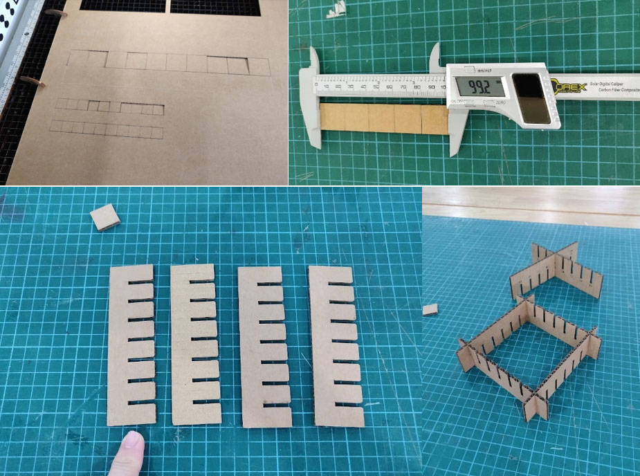
We have characterize the focus, power, speed and rate. We made a sample of the cutting to find the kerf while cutting and a board comb to see the joint clearance.
The best outcome for the cutting was around 40% power and 40% speed, with this setting the cut was clean and it went through, not burning too much the cutting lines.
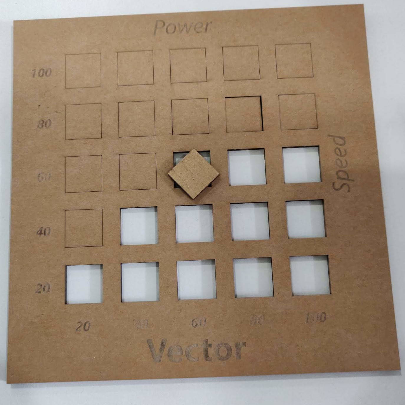
The Kerf gave us 0.1mm, that then I had to take into consideration when designing the slots of the construction kit and the design of all parts.
INDIVIDUAL ASSIGNMENT
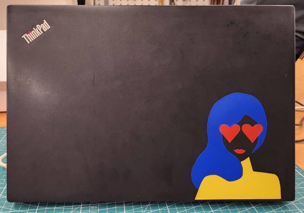
-Vinylcutter-laptop Sticker
The vinylcutter is such a fun machine, we can create logos, illustrations and in seconds just cut them up and we have...stickers! a very nice way to personalize our laptop or notebooks, so this is what we made this week.
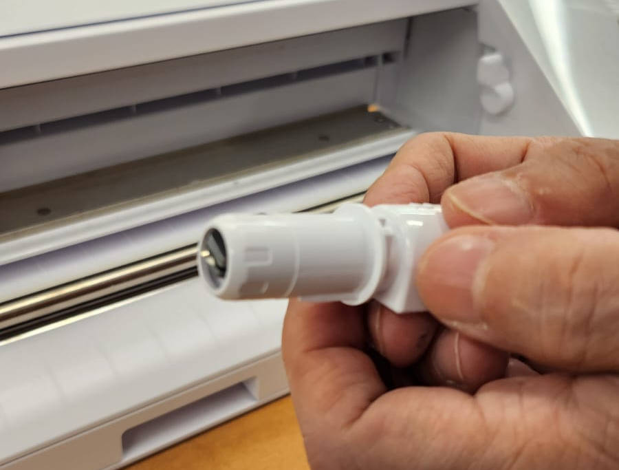
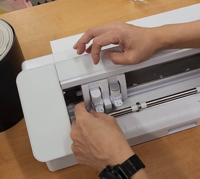
Our fablab has a "Silhouette CAMEO" Vynilcutter, it works with its own software to print the images to stickers.I will show the process of the sticker design and the machine settings.
We have to make sure the blades are installed correctly and they are just sticking out from the cartridge
|
|
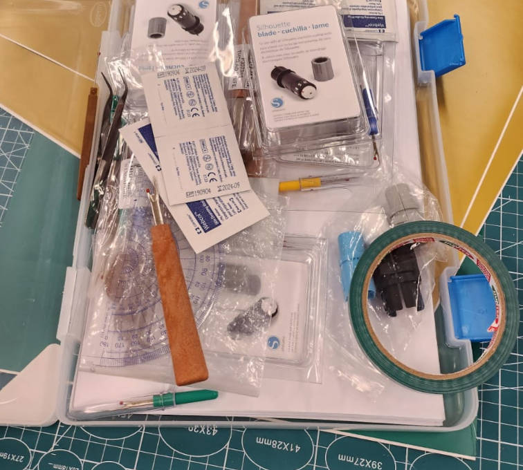
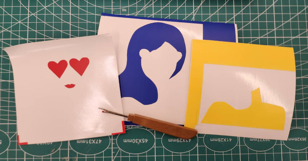
There are several tools like the weeders, scissors, alcohol pads to clean the surfaces before putting the sticker on, cutting pad to put small sizes of vinyl and prevent it to move while cutting, etc.
|
|
Design and Cutting:
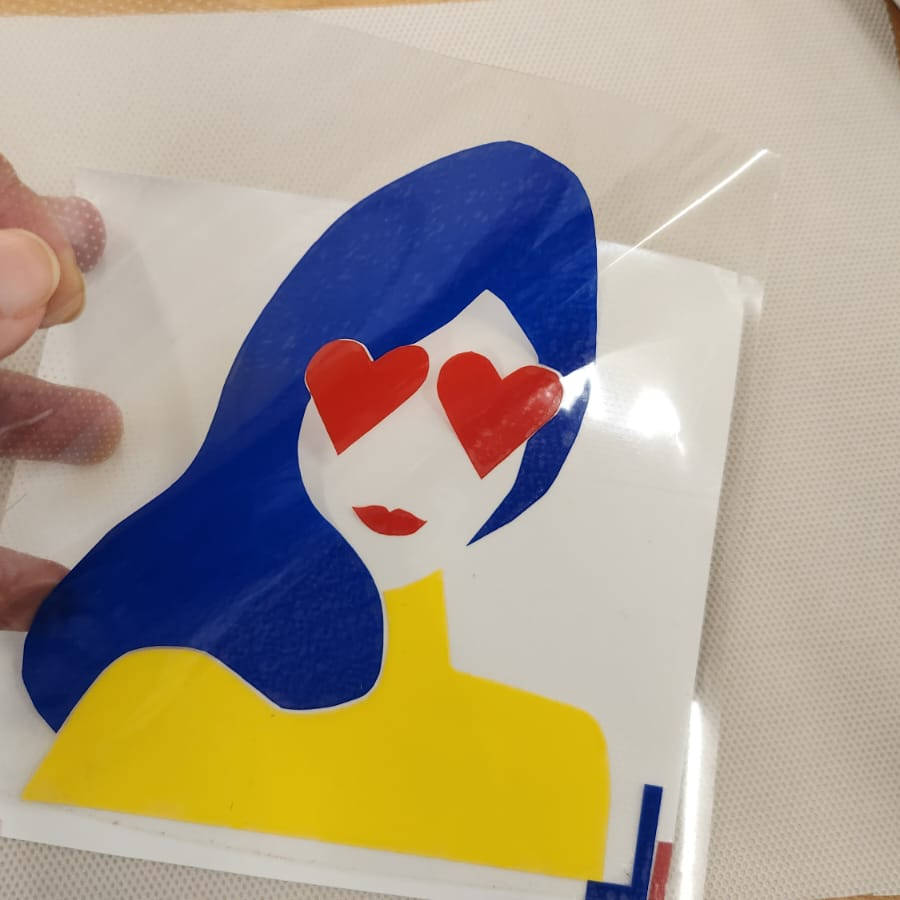
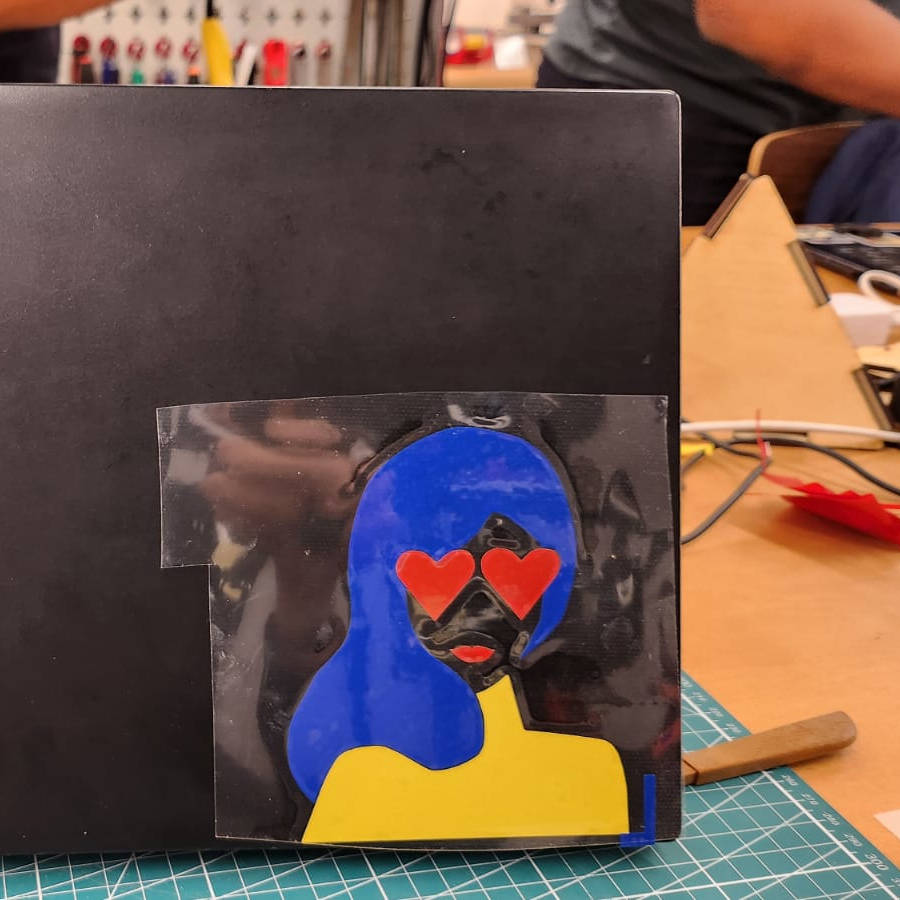
I found a pretty nice illustration from LISA PROCTER, an American illustrator and designer. The image has quite few elements but is still very powerful, I wanted it to have more vibrant colors and be easy to find at the Fab Lab, so I chose Blue, Yellow, and Red.
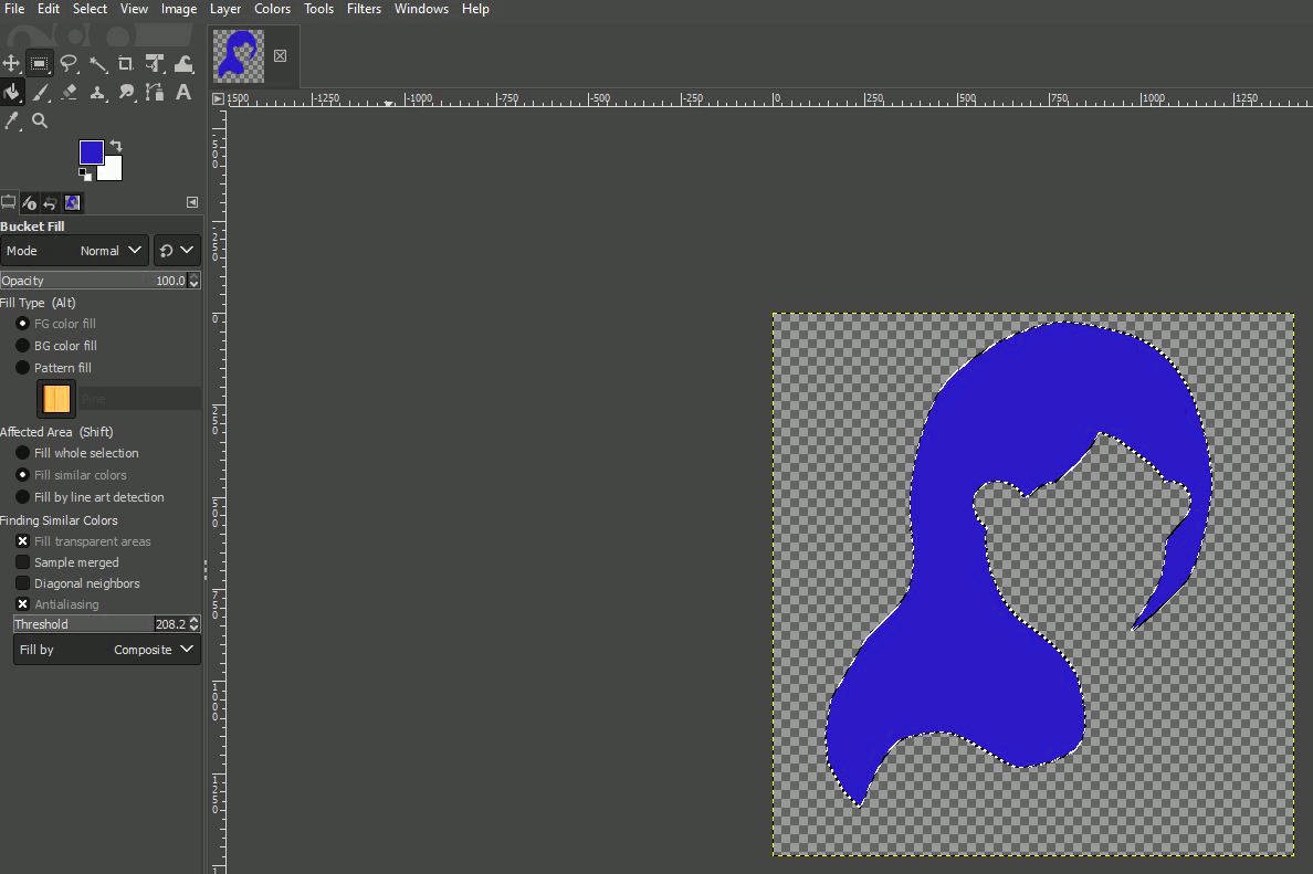
First I opened the original photo in GIMP, and open-source program for raster image edditing, I scaled the image so I could mark the areas where I wanted the different colors.
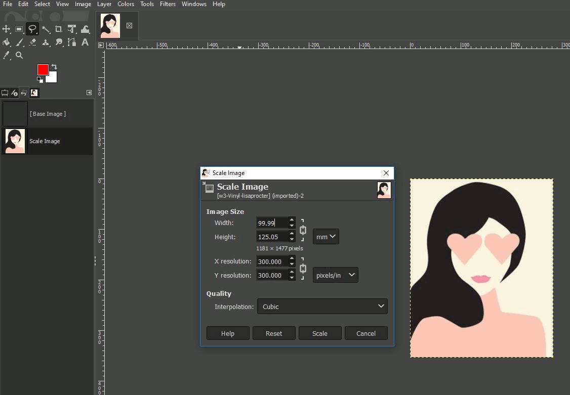
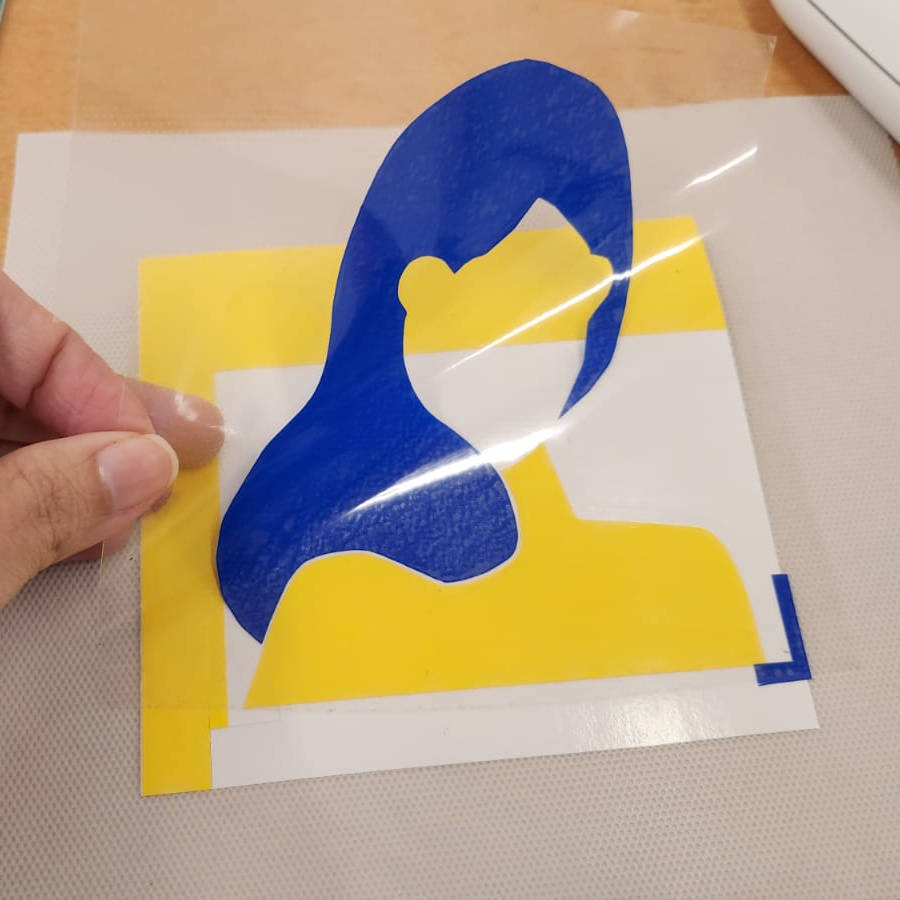
Then I created three different layers for each color of the image. I selected with the magic tool each existing color and with the bucket tool I filled with the desired color, this part is important as later each layer of color will be saved in a different file for cutting on the machine

|

|

|
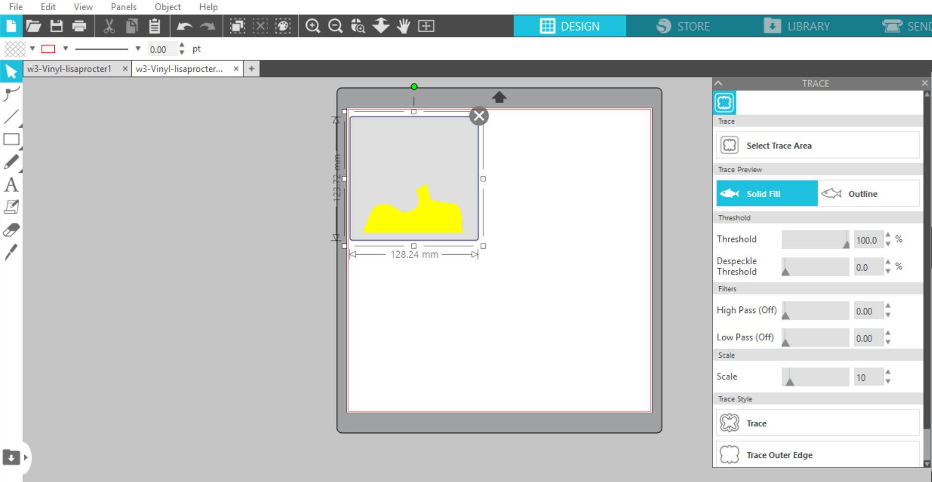
Having all three layers made into files, I open them in the Silhouete Cameo program called "Silhouete Studio", I click on the trace tool and marked the area for the program to recognice the shape to be cut, here it is very important to tune the "threshold" button, if it is too high as I did in this picture the program recognices all the pixels of the border and the final shape wont be even, so I have to lower down the "threshold" to aprox 40%, just enough to recognize the area but having nice borders. Then we should click on the lower button of "Trace" and it will appear a red border line that will limit the cutting area.
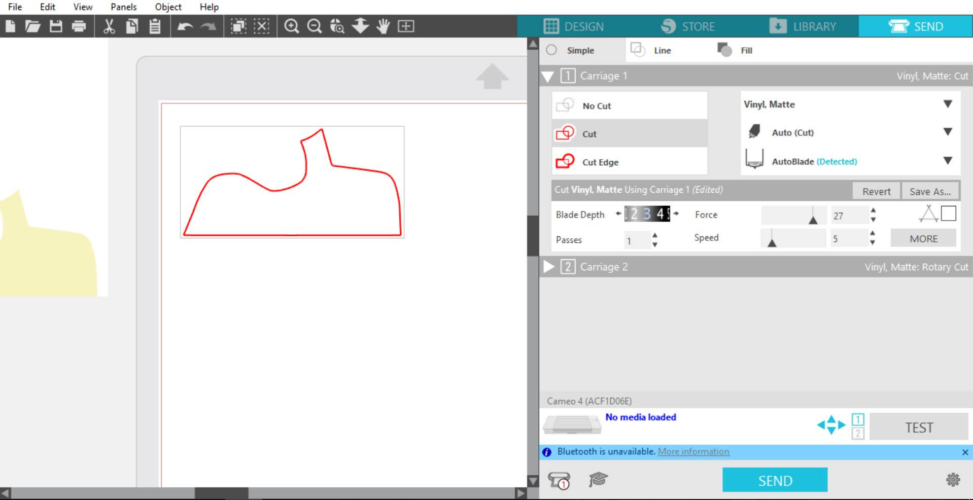
Once we have the cutting area bounded we click in the upper button of "Send". Here a new window opens and we should click on the image then select "cut" from the options of cutting, select the material, in this case was vinyl matt, the blade depth on #3 (as this material is quite hard), force of 20, speed of 5. We should make a test first, clicking the button "Test", there will be a small cutting test to see the blades are cutting in the right way, no too deep no too shallow. If the test is right, we hit the "Send" botton at the lower part of the window and the machine starts to cut.
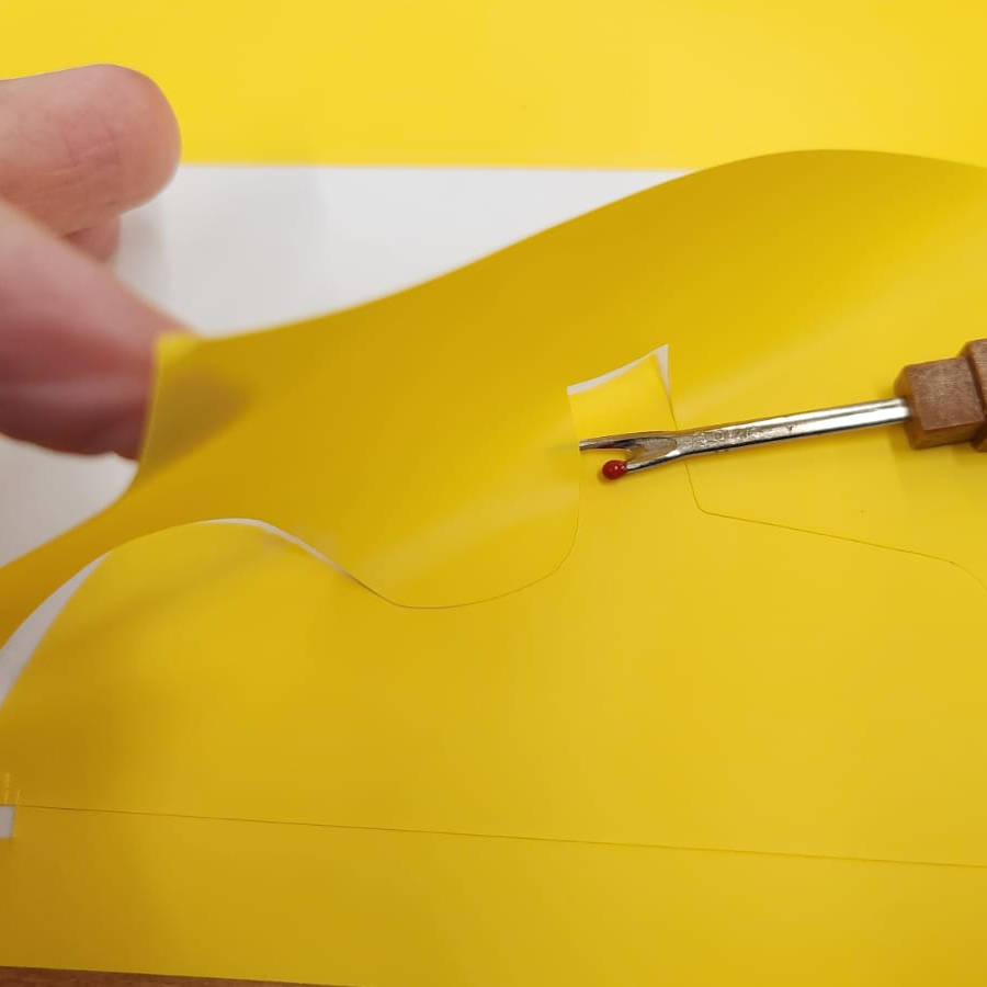
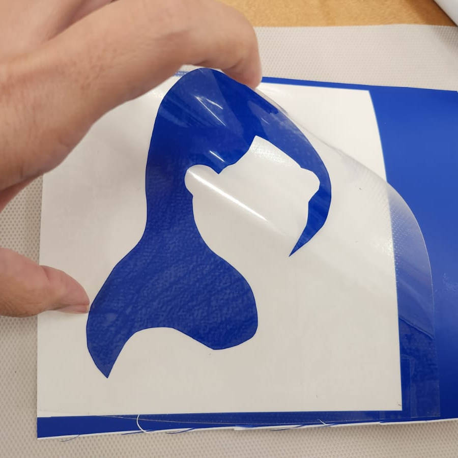
I did this process for the three colors and cut them, then it comes the weeding process. For it we need the weeder and go through all the cuttings and taking out all the unwanted parts of the stickers
|
|
|
|
|
|
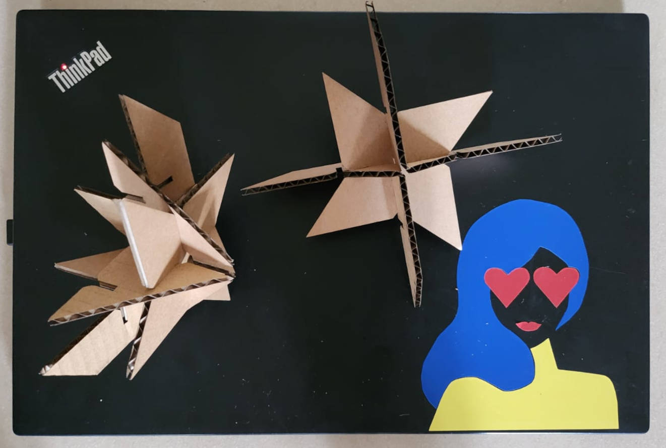
-Construction kit
I started having a lot of fun, I was full of ideas...an finished a bit frustrated. But then I reminded myself about the spiral learning and how this project could be a design exploration. I am the kind of person that has a broader way of thinking, what I mean with that, is that I start with "big" ideas and sometimes they are not easy to do, nor possible to do or the final outcome is not what I expected...and in top of that, I have really high expectations. So let's see what happened.
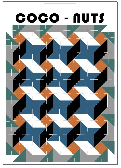
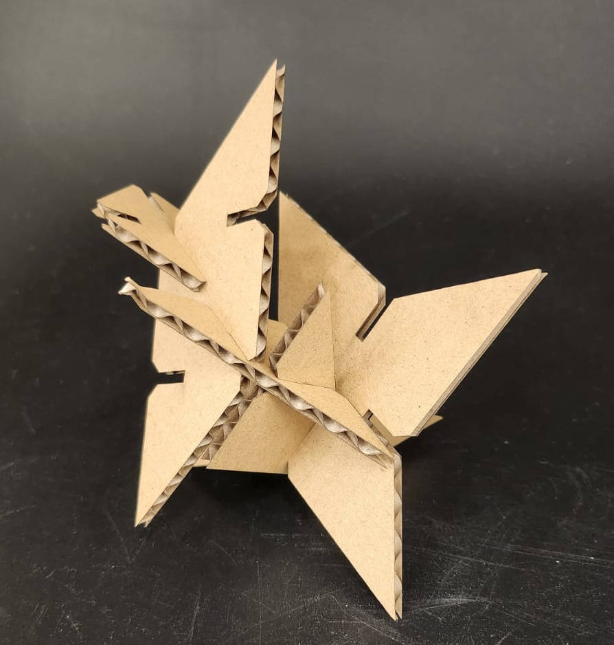
-Design Fase: "coco-nuts"
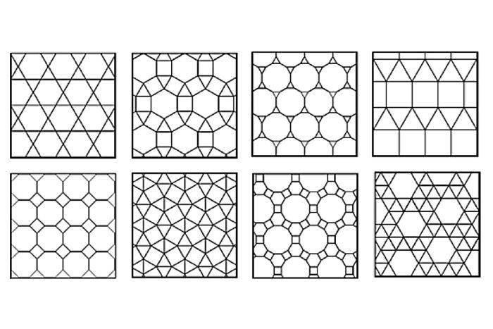
I have been always attracted by figures that can be repeated to create another figure or pattern, there is an "Artist" that makes a lot of this with "TESEELLATIONS OR TILES" Escher, this geometric models are common too in the Islamic world. Then I had the idea to make a 2D design of the Kit modules as a pattern where there is not empty space between the modules, they could be laser cut and later we could make a 3D model with the parts. Pretty cool idea! (off course the last thing that came into my mind was the parametric part of the exercise).
I tried to explain the idea to my fellow students, they did not get it, but Steven our FAb Academy instructor understod it, and said it is like the coconut, you use all of it. this is what I wanted, to laser cut the cardboard surface with no space between the 2D modules, starting from a 2D design, so I decided to call this kit: "coco-nuts"
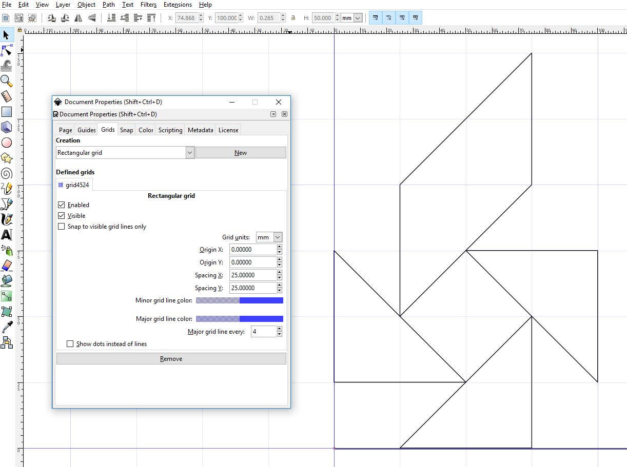
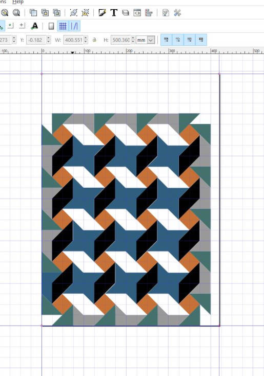
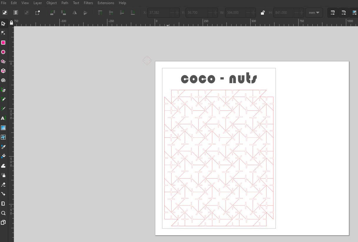
So I started to do the 2D layout in INKSCAPE, an open-source programm for vector illustrations or image editing. I created a grid with the general sizes of the shapes and traced the modules I wanted, with repetitions, then filled with colors each module and drew the slots where the modules could be ensembled together.
|
|
It took me quite long to get into the aesthetic of the design forgetting the aim of the excercise, I started quite late with the model design in FUSION 360. I tried to do the same as I did with Inskape...
-Fusion 360 and the acumulation of errors:
I spent long hours making the grid for the modules, then I drew the modules in top of it, making layers and layers of information, that weren't need it, I should've started making the modules straight away as I already knew the measurements from the 2D previusly done in Inkscape. Fusion got a bit "coco-nuts" with all the lines I drew on it.
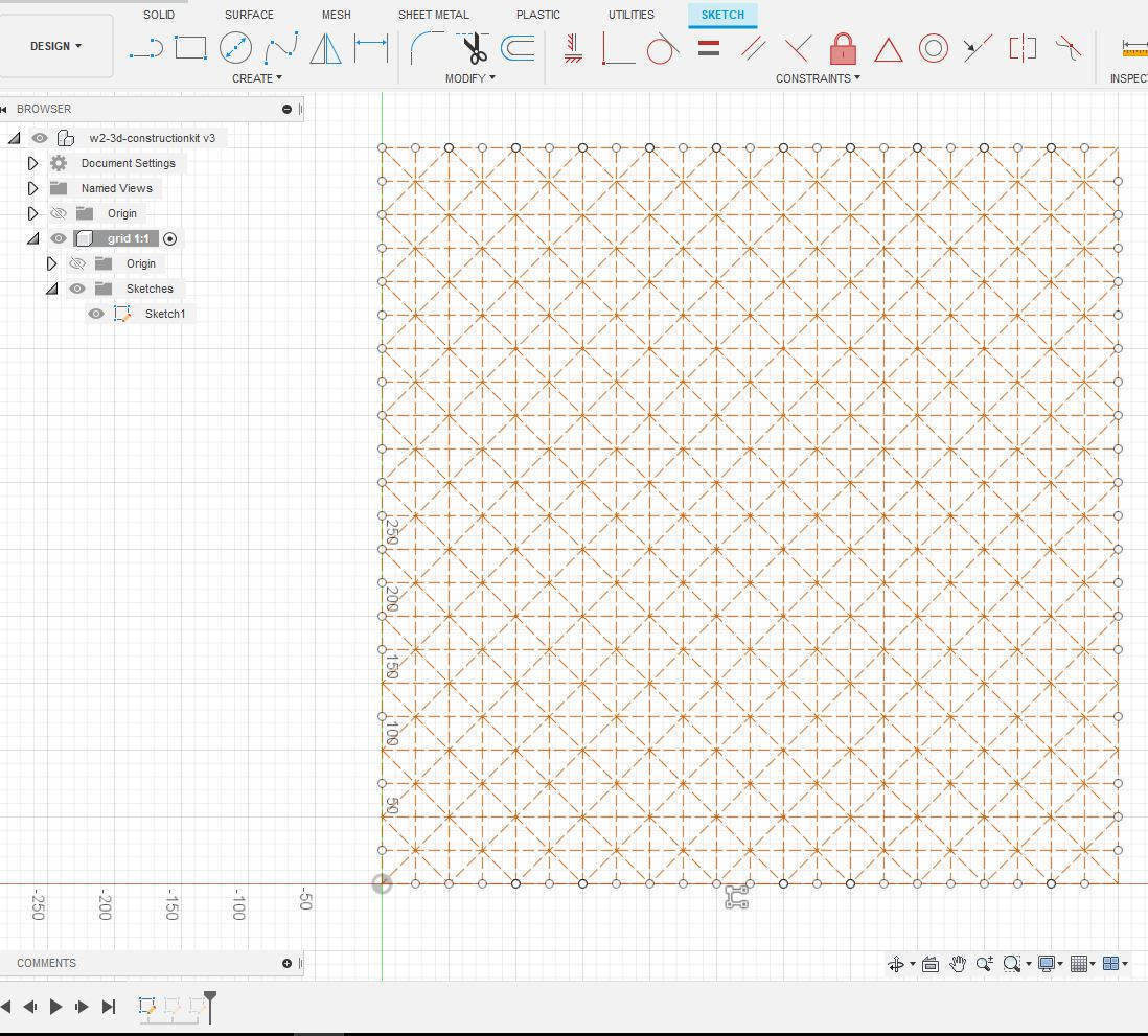
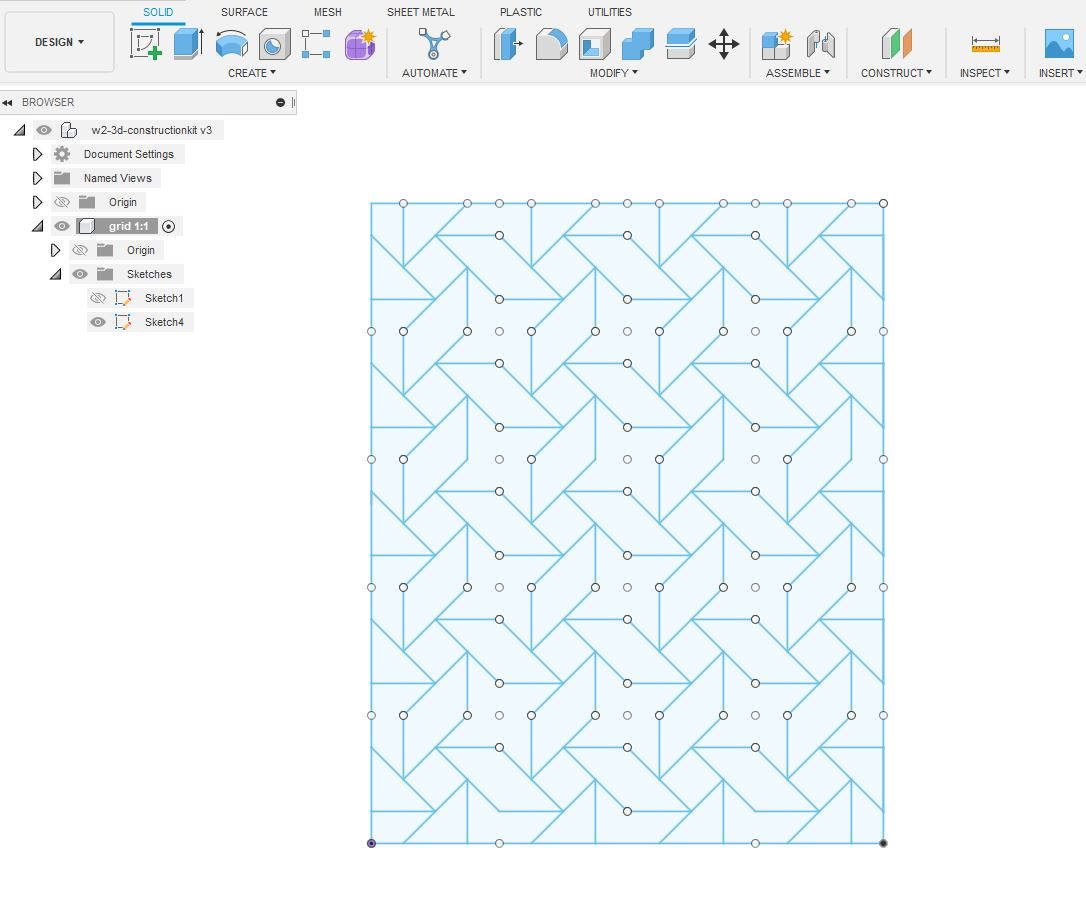
I got a bit lost with the layers and the shapes drawing,although I assigned the parameters and constrictions to the Sketch shapes they were not parametered! not a single line turned black and I could not scale the drawings with parameters.
-A new file:
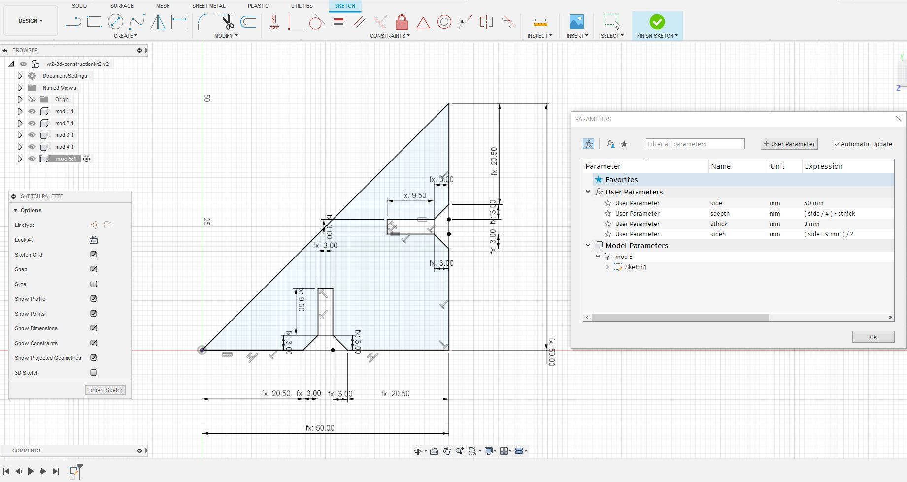
Then I started a new file from scratch, and did what I had to do from the beginning...drawing the shapes without the grid, then Fusion loved me again, then I constrained the drawing. Before I watched some tutorial videos, as I didnt know well how to do it. Check this guy for USER PARAMETERS IN FUSION 360.
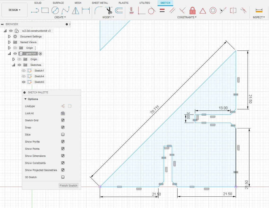
suddenly everything started to go smoother, I assigned the parameters to the triangle sides, the slots and the lines of the figured turned black! I could scale it changing only the value of the triangle sides, mantaining the thickness of the slot.
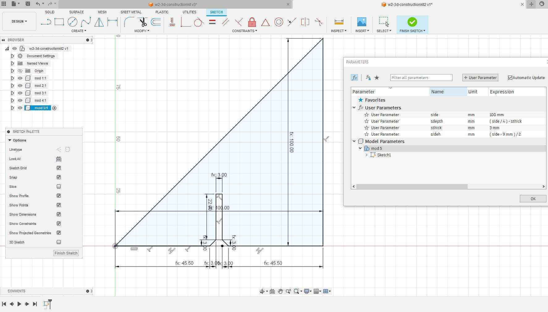
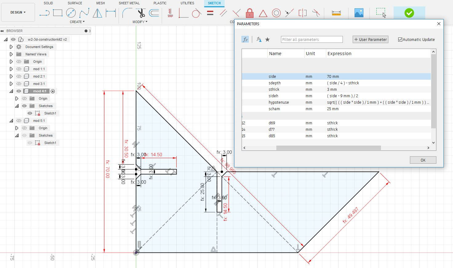
I continued creating another slot in the figure for future 3D construction, and then again Fusion 360 got a bit "picky" my sketch was over-constrained, if I tried to change the scale it will deform the figure shape. Somehow I fixed the problem by erasing some constraints and adding others.
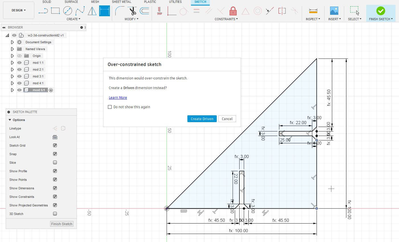
This triangle was working properly...but then I got into the "rabbit hole of the parameters" with the other shapes as they were a bit more "complex". I have to be honest...I got so confused with the "parameters" and they didn't make sense anymore.
-Over drawing problem, try to keep it simple:
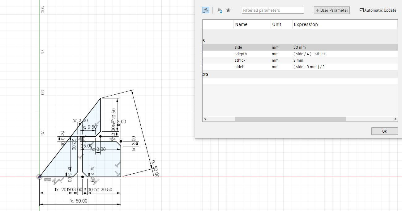
Later I got to know that I shouldn't have made the chamfer slots in this stage of the drawing and much less put parameters to them! my sketch figures were getting these little angles everywhere and I was putting constraints and parameters on them.
My design has 6 figures, and at the end I could do only two of them with Parameters. The parameters should've been simpler, the chamfers should've been done to the 3d Object and they should've not be parametered...an advise of some fellow students.
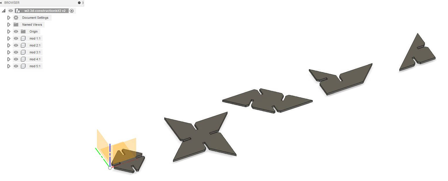
-Making the 3D shapes finally:
It was the end of the weekend already, and I was just starting with the 3D figues, I decided to leave the Sketches as they were and continue with the assignment, but again, another challenge created by myself.
To be more "organized" with the drawing I decided to do each shape in a separate "Component" and this turned out to be a nightmare! as each shape had its own sketch and sometimes I switched between them not noticing it and couldn't find my way out! PLEASE, if you are new to Fusion 360 try to keep it simple! I still learning how to get in and go out from each working space, I get confused with the history, the workspaces and the folders tree.
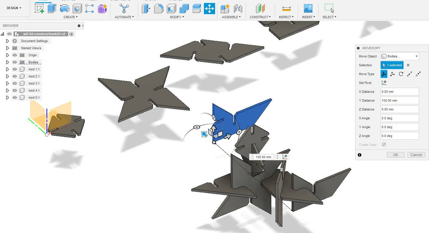
Confused as I was, I found my way out and made the first 3D "construction" of the figures and ensembled the kit. Rotate and move the figures was pretty straight forward, once activated the "move" tag, appears a window and arrows that make easy to move them around.
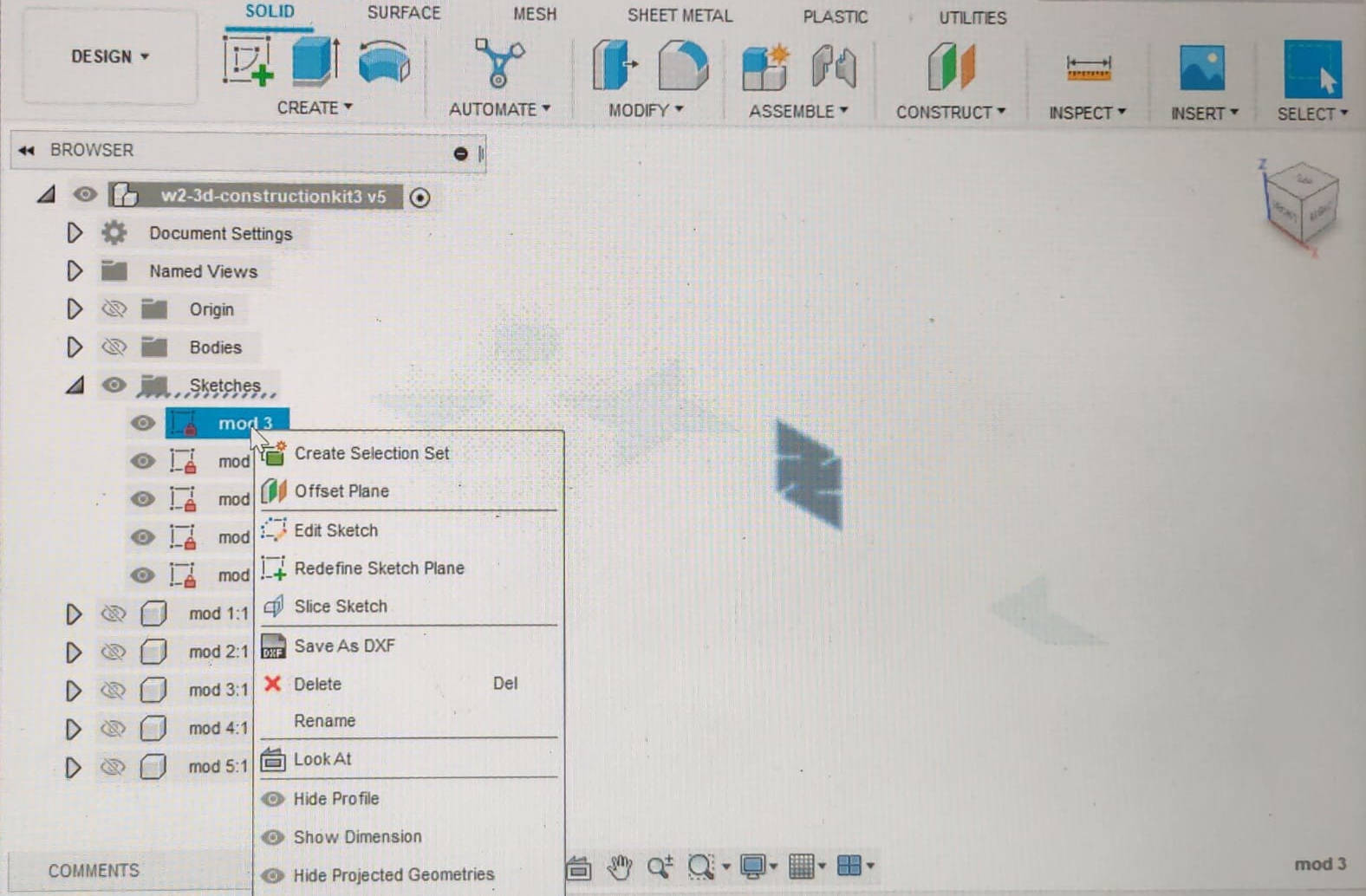
-Preparing to Laser cut the figures:
From the 3D objects in Fusion 360 clicking the top view of each shape I created a new Sketch for each figure. Standing on each Sketch and clicking with the right mouse button I saved them as DXF
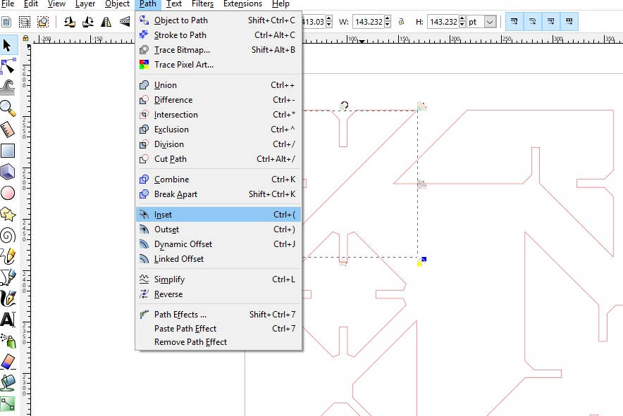
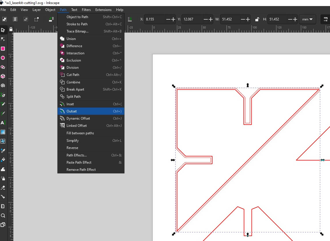
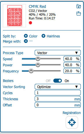
Once all the shapes were saved in DXF, I imported them to Inkscape to do the Offset for the "Kerf" that we established in our Characterization of the Laser Cutter. We determined that for a Speed cutting of 40% and power of 40% the cut was optimal. This gave us a "Kerf" of 0.13mm, it means the shape we did in Fusion has to account for the 0.13mm of the material lost in the cutting. To solve the material lost in the cutting we do an "offsetting" of 0.13mm to outside of the original shape polyline we have imported to Inkscape...but wait...
-Another stone in the path: Inkscape crashed!
Well yes, Monday noon, and I haven't laser cut my kit, and was about to prepare the template but my Inkscape crashed. When I selected the object and tried to do the Polyline "Path-outset" to do the offset, we noticed that the pointers of the shapes where not showing properly, after a lot of trials and errors, Steven suggested me to install the PORTABLE VERSION OF INKSCAPE This was a life saver!
|
|
-Laser Cut sample: first cut!
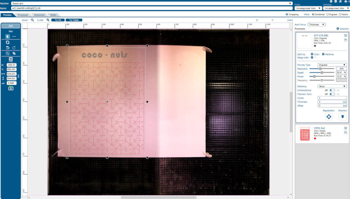
Once I could do the offset of all the shapes, I sent the file to Corel Draw, the default program used by the Laser cut machine. Knowing the settings of Speed cutting of 40% and power of 40% as optimal for the cutting, I set them at the laser cuter and I made my first cut, it turned out to be good!
I ensembled the modules together and the kerf was perfect, ready for the final cut! But the day was over so I had to go back on Tuesday to make it.
|
|
On the morning, before going to the Fab Lab, I worked on my initial idea of having all the pieces printed without leaving spaces between them...making my life difficult!
In the Inkscape file, I mounted the pieces that have the "Kerf" together to make the previous 2D design. I mounted the small module version (Paper Size A2, modules of 50mm grid) and the second version, scaled modules (Paper Size A0, modules of 100mm grid) and left to the Fab Lab.
It was already Tuesday early afternoon, what could go wrong? It was just laser cutting and I have done the sample the day before that was perfect.
-"Anything that can go wrong will go wrong" Murphy's Law, Tricky Laser Cutter:
When I arrived to the Fab Lab I went directly to the Laser Cutter were we have done our group assignment of Characterizing, it was a obvious desicion as I already knew how the machine worked and knew the settings to do the "Optimal" laser cut.
|
|
I couldn't be more wrong...there is something important we should take into consideration, some of this machines are heavily used, in my case for the Polytechnic Students, it is really well mantained but it is asking for a general specialist mantaincance. So when the machine was in the process of cutting half way I noticed two things:
-
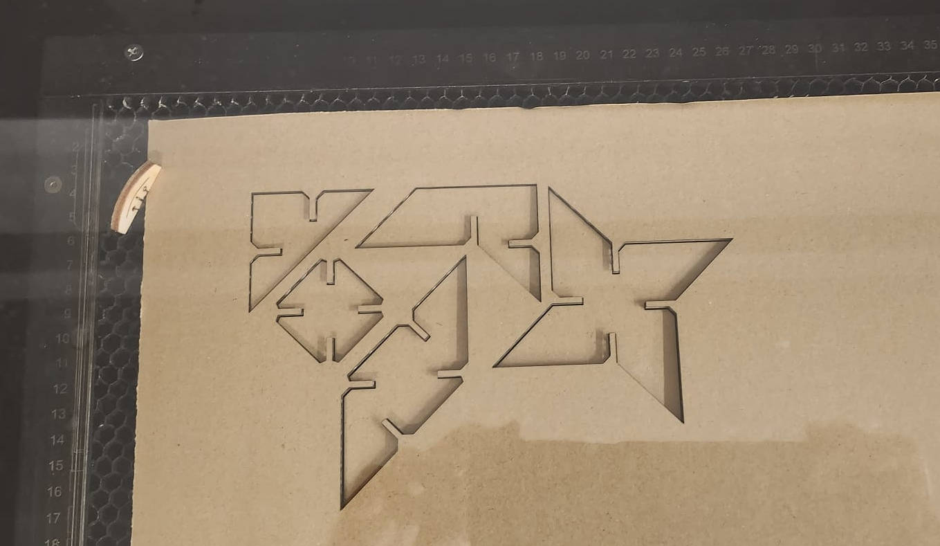
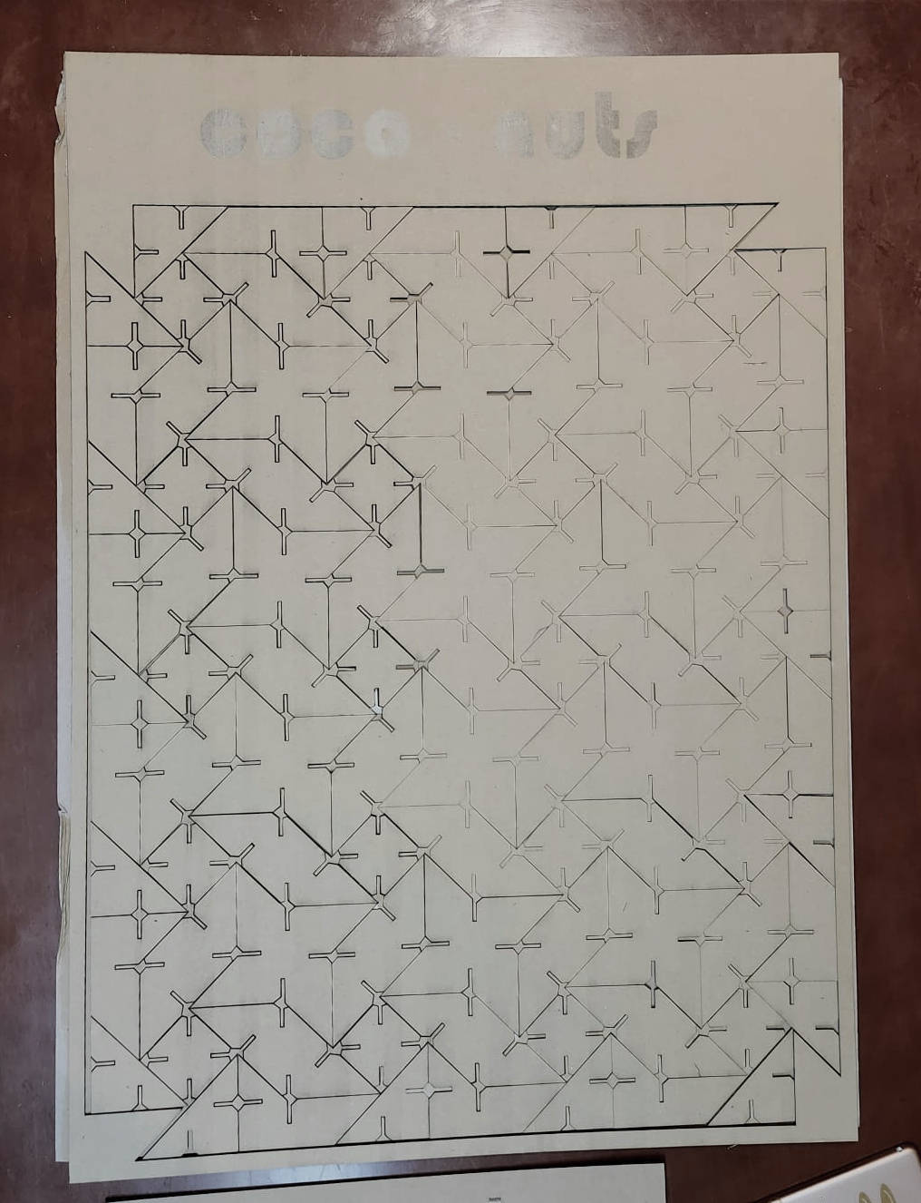
Laser cut double pass: the laser was going twice through the same line...of course, the template I brought had the figures sticked together! the machine program read the lines twice, so cut them twice...
Lesson if I want to do this kind of continuous figures, it is better to do the cutting design directly in the Vector program so the lines are not repeated, or if the shapes are imported from the 3D like I did, I should've edited the shapes when I put them together in the vector program to have only one line between shapes.
- Out of focus: The first half of the cutting was very clean, although it cut twice over the same lines, but then the lower part of the cutting, half way of the cutting, the lines started to become thicker and thicker!
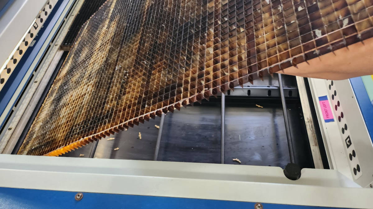
I asked the Lab manager if he knew what was happening and he came to see. Theory one, the cardboard was too bended, which was true, so we started to do some cutting samples with a neater cardboard again, and still the same problem of the lines becomeing thicker in the lower part of it.
Theory two, the metal grid of the Cutting bed, where the material sits, was not leveled. It was a bit bumpy so the manager flipped it over, then was better, we did another cut sample, still we saw the same problem.
We could determined that from the half to bottom and right area of the laser cutter it is totally out of focus, it took us hours to sort it out, this means the beam of the laser wasn't cutting properly making a thick cutting line and not passing through the material.
|
|
-Solutions:
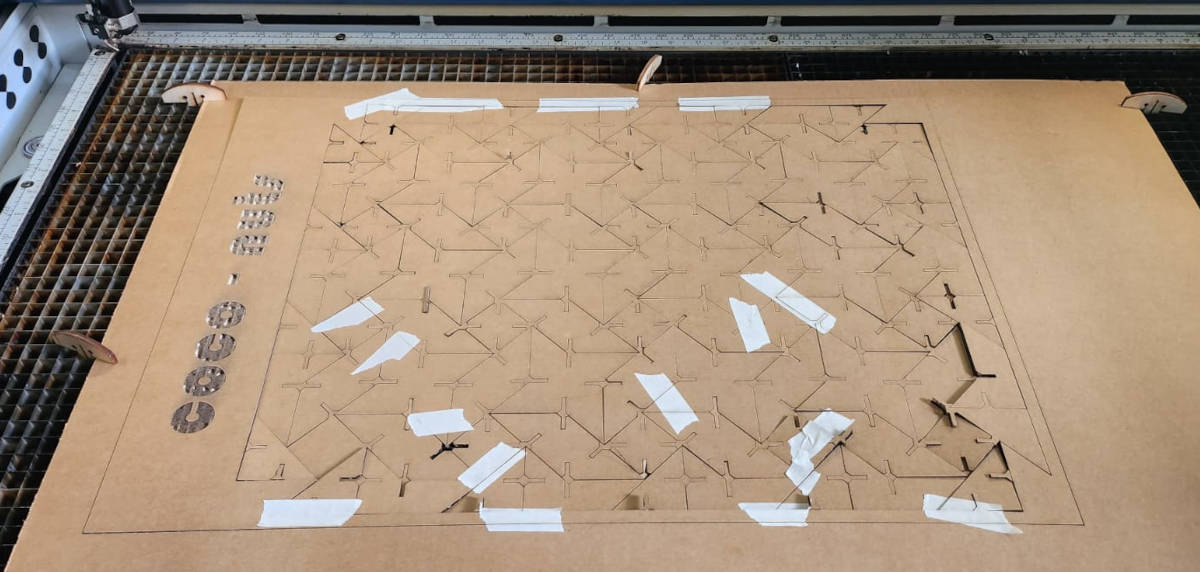
- I Changed the laser cutter settings to have more power, before it was 40% speed, 40% power, I changed to 30% speed and 50% power. And as we determined that the lower part of the laser cut wasnt focused I rotate the cutting to landscaping, this helped to avoid the worst part of the line thickening but still it wasn't perfect.
-
I put masking tape to some of the pieces to mantain their level, this was important as the laser passed twice throught the same line.
Because The cardboard was quite bended I clamped it, but then while cutting there was tension realeased from the bended cardboard and the clamping, and it bended back. I paused the laser sometimes to hold the pieces with masking tape.
- Doble pass of the laser in the parts that were not cut throught
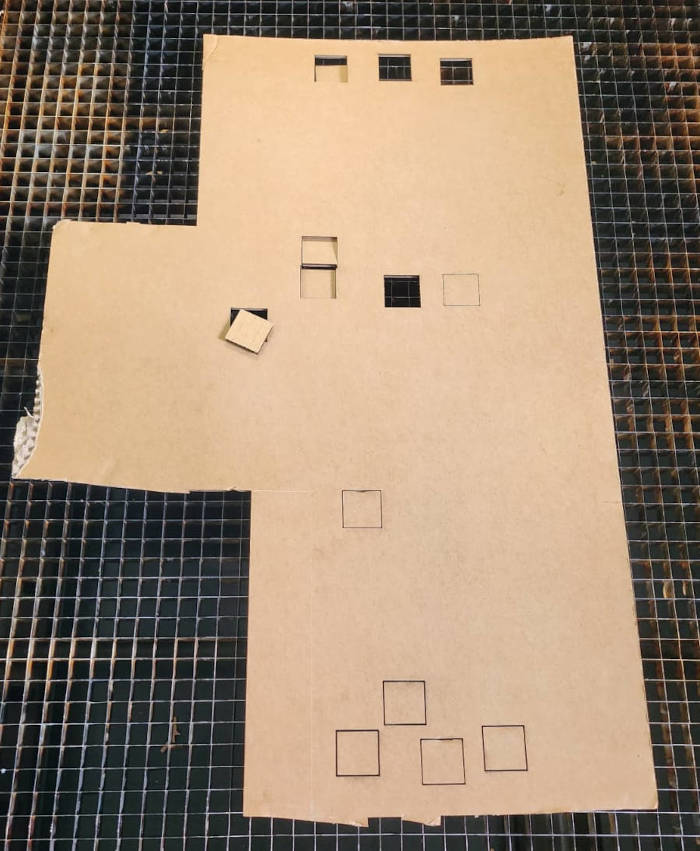
-Finish line, "Sticking to my Guns":
I proceed to cut all the modules but it was almost difficult to avoid the lower area of the machine, where the laser focus was not good, so for this part I had to pass the laser twice...
It would've been easier if I just had the peices distributed into a cardboard and could've moved them around to avoid the out of focus areas in the laser cut machine, but at this point of time I wanted to finish the project that I have been developing for a week, "Sticking to my Guns".
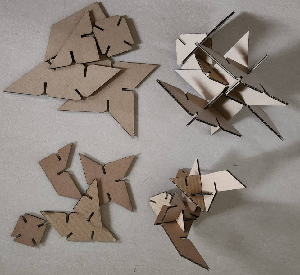
At the end the result was not as expected...but got my modules. There are more laser cutters in the Fab Lab, so next time I will try with a different one.
|
|