dummy
8. ELECTRONICS PRODUCTION
This week hands on to manufacture our Electric Boards we have designed on week 6.
We will be milling them in a small table router, soldering the circuits, and running the programs we develop for them.
HERO IMAGE
ASSIGNMENTS
Gropup Assignment
- Characterize the design rules for our in-house PCB production process: document feeds, speeds, plunge rate, depth of cut (traces and outline), and tooling.
- Document our work on the group work page and reflect on our web page what we learned.
Individual Assignment
- Make and test the development board I designed to interact and communicate with an embedded microcontroller.
GROUP ASSIGNMENT
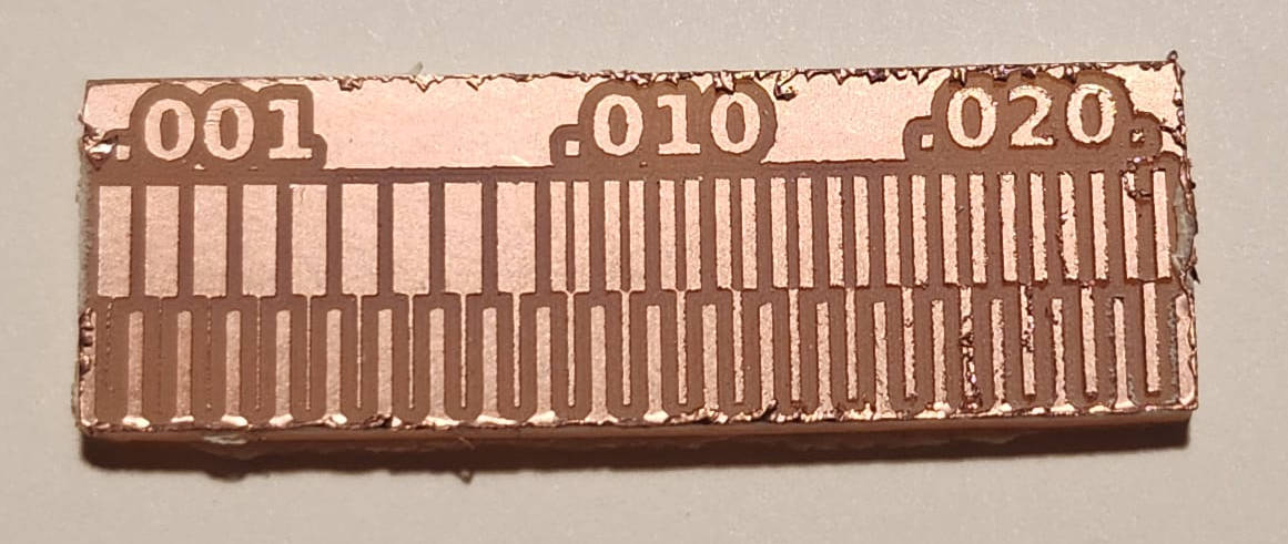
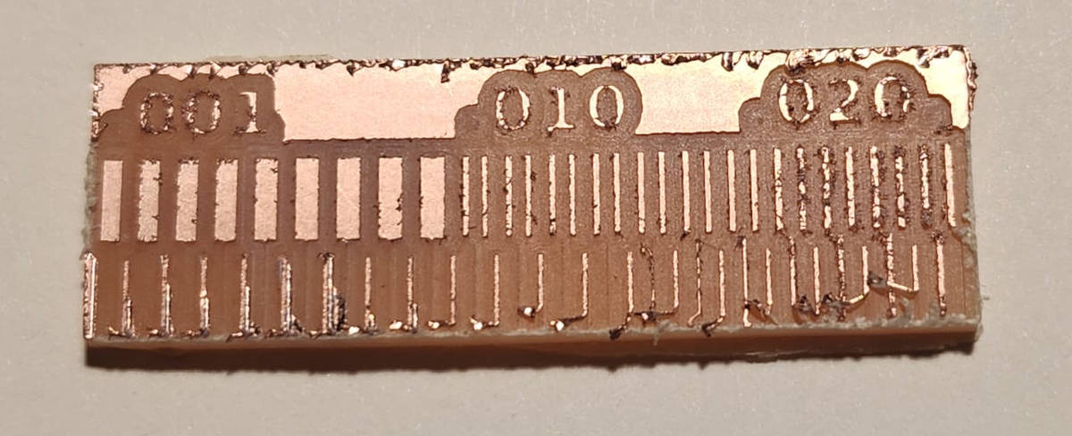
After going trough the milling process and trying two different sizes of End Mills to do the traces, we could see that the V-Bit of 0.1mm gave as a cleaner finish, a more detailed lines. So I decided to make my board with it.
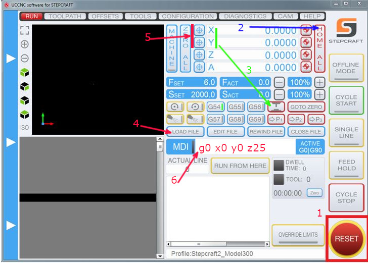
The Software to open the G-code and set the machine start point was easy to do, perhaps it felt easier because we came from the Machine week using the CNC Big format Milling machine.
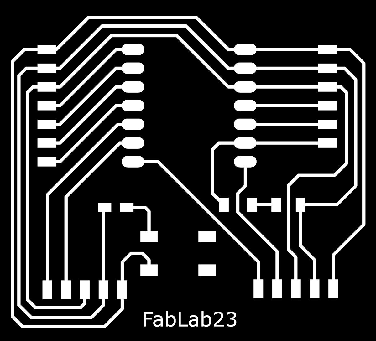
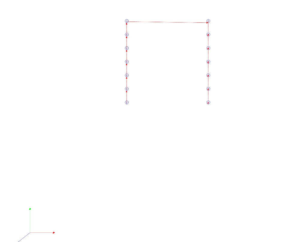
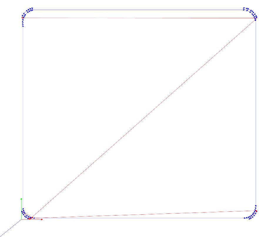
First image is the Traces with V-Bit 0.1mm and the second is with the Flat End Mill of 0.4mm
|
|
You can see HERE more about the group assigment, where we see more in detail the CNC machine operation
INDIVIDUAL ASSIGNMENT
-Revising the Board Design and generating G-Codes
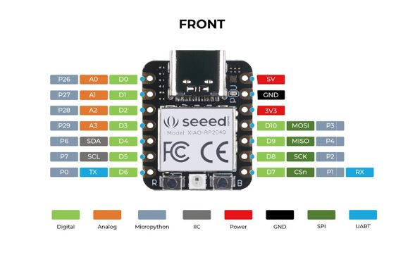
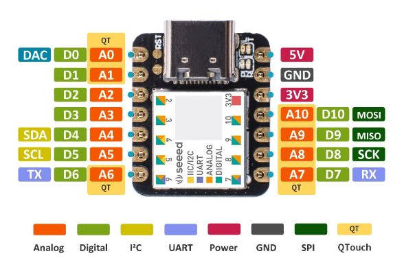
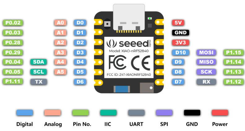
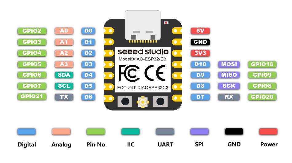
The general concept of my board is to have a Led that can be turned on/off with a Push button integrated into the board and to bring all the Microcontroller pins to external headers where we can connect different components, creating a kind of Breadboard.
The connection of the Microcontroller is done by External headers too so I can switch to other models of Seeed XIAO if I want, using the same board.
Seeed has OTHER THREE MODELS which are: the SAMD21, nRF52840 and the ESP32C3 , all of them have the same quantity of Pins and they are organized in the same way as the RP2040, so in theory this board can be used by any of this models.
|
|
|
|
I started revising the design we had done of the PCB in week 6 and we made sure the G-Codes were generated with the correct settings.
First I had to fix the PNG files as I had the black and white wrong in the Outline file. Always Black is the part we are going to mill away and White is the part that is not being milled. So I checked all files where accordingly.
|
|

|
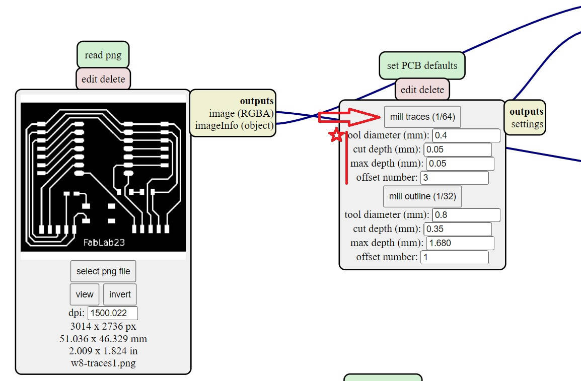
As the PNG files were ready, I opened Mods and the PNG files of the Traces, Drill holes, and Outline.
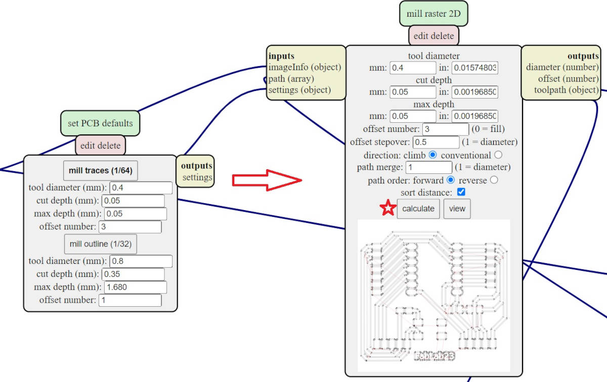
-Traces settings
As we open the PNG, we go to the window Set PCB defaults, we choose the thickness 0.4mm (1/16), our end mill will be 0.4mm diameter, cut depth 0.05 mm and an offset of 3 passes within the traces.
-Milling speed
We go to the window Path to G-Code we choose 60mm per minute as our CNC works with minutes. This version of Mods has been modified by our Instructor Steven, to convert the minute rate to seconds rate by itself. The spindle speed has to be set manually at the CNC for our model.
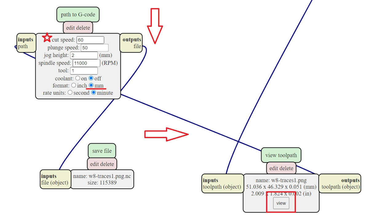
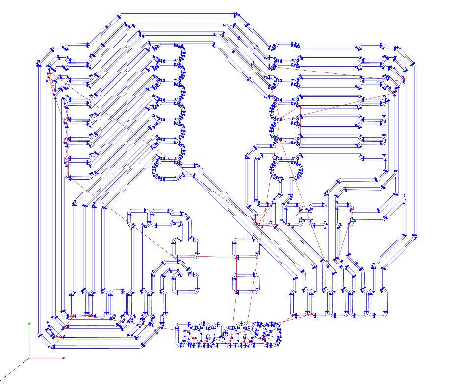
-Genrate the G-Code
All the settings we have done are sent to the window Mill raster 2D, we click Calculate and it will generate the G-code for us. We can visualize it first to see if all the paths are correct and if there is no clashing between them
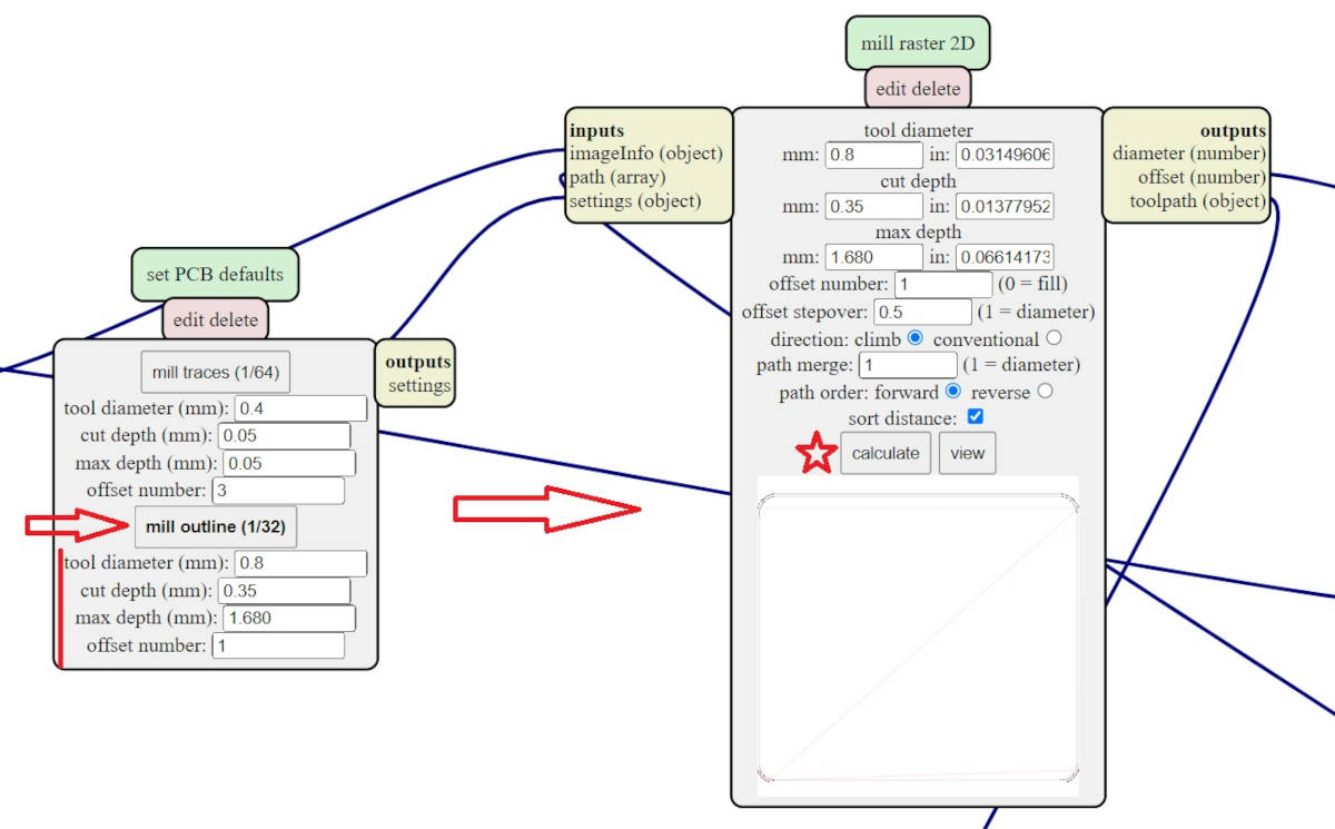
-Drill Holes and Outline settings
Although they are separate files, we do the same configuration and if we don’t get the desired result we can change the end mill for the drill holes or the Outline.
At the window Set PCB defaults we choose mill outline the tool diameter 0.8, as it is to cut through a bigger diameter is good, for the cut depth we choose 0.35 max depth 1.680 and an offset of 1 as we just want to cut through.
The cut speed is the same as the path setting.
-These are the images of G-codes files:
|
|
|
-Milling the Board
Before milling any of the G-Codes I revised they had the same insertion point and sizes…but they hadn't. When I generate the PNG images from Eagle-Fusion 360 I clicked for the Area WINDOW instead of FULL and that changed the insertion point to a relative location.
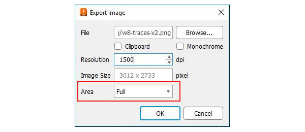
I exported again the images to generate the new G-Codes with the same insertion point and opened them in the computer that is connected to the Router, I had to set each one separately for milling. These are the CNC Machine setting up steps:
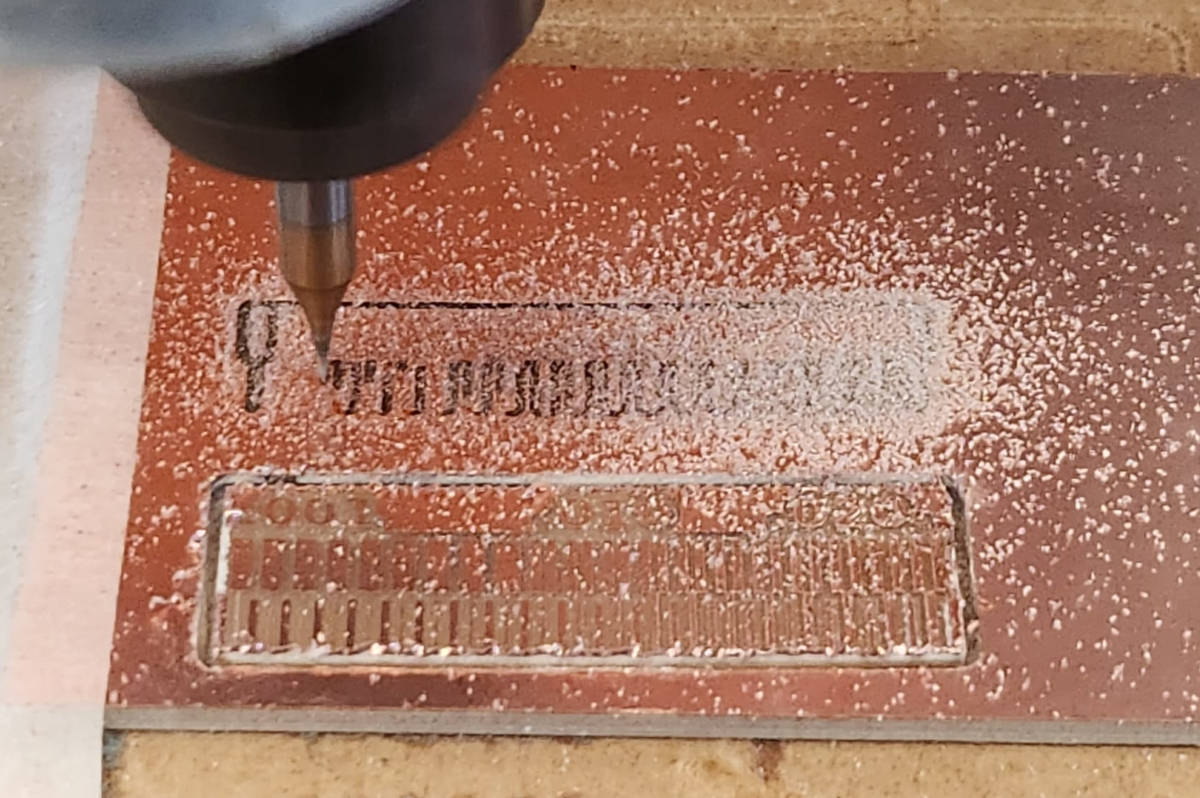
- First, we put the copper plate on the router bed with adhesive tape in the back and masking tape on the sides to prevent it to be moved while the milling process, install the end Mill of 0.4mm, for the paths we choose a V-Bit type of 10 degrees, as it gives a pretty clean line.
- We set the Z value with the sensor
- We set the X and Y value for the starting point and move the CNC Z value to 25.000 height. It is a good practice to go all around the paths with the pointer at the screen to make sure the milling doesn't exceed the size of the board we are using.
- Then we click on CYCLE START and the Milling starts
- Once the Paths milling is done we upload the Holes G-Code and proceed to change the end mill to a flat bit of 0.8mm as we don't need detail but cut through. And set again the Z value with the sensor as we did with the paths file. We don't have to set the X and Y points as we are using the same as the previous file. We click on Cycle start.
- Once the Holes are done we open the G-Code for the Outline as we are working with the same settings we just have to start the CNC with the X, Y points, and Z in 25.000 Height.
Soldering the components and parts into the PCB Board
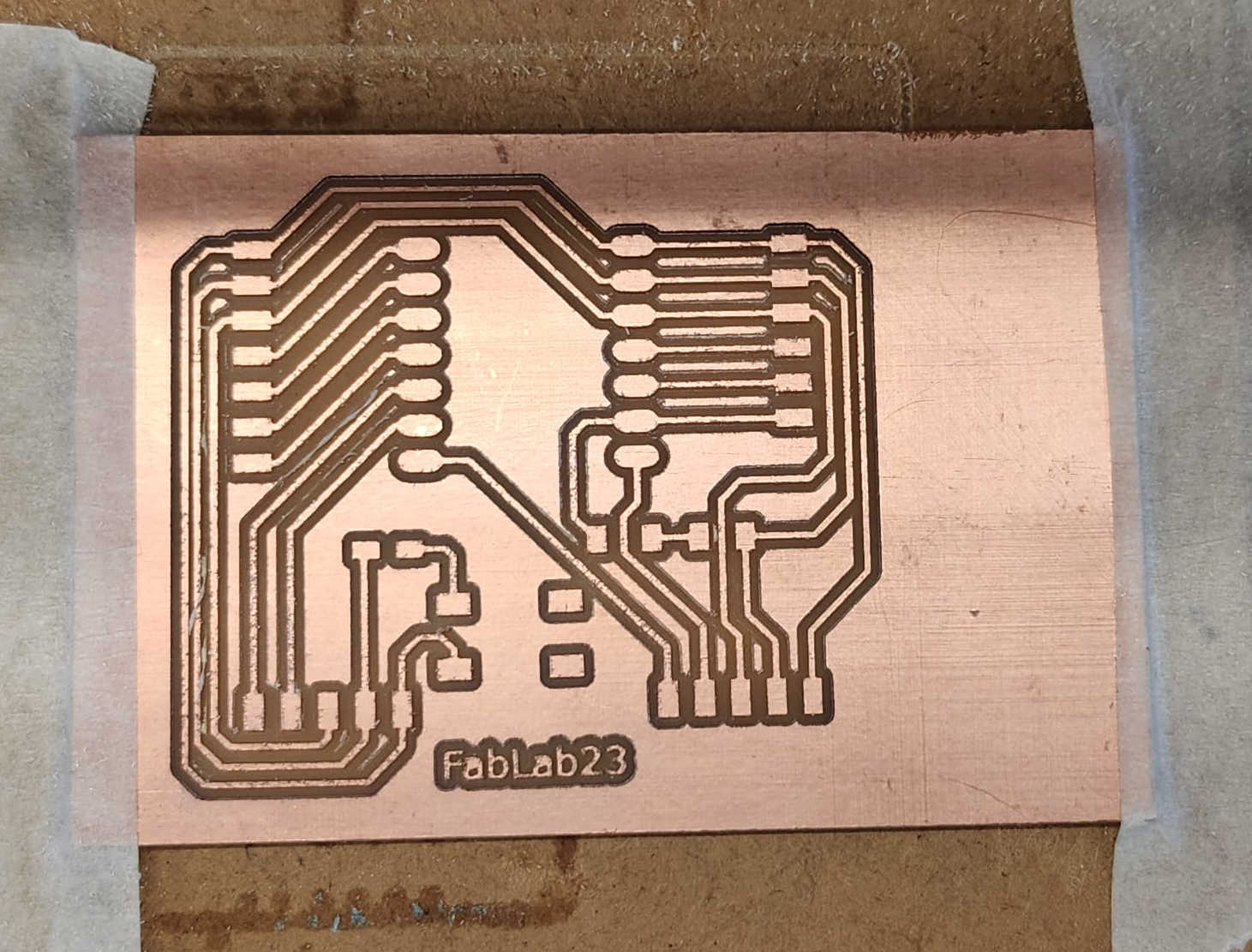
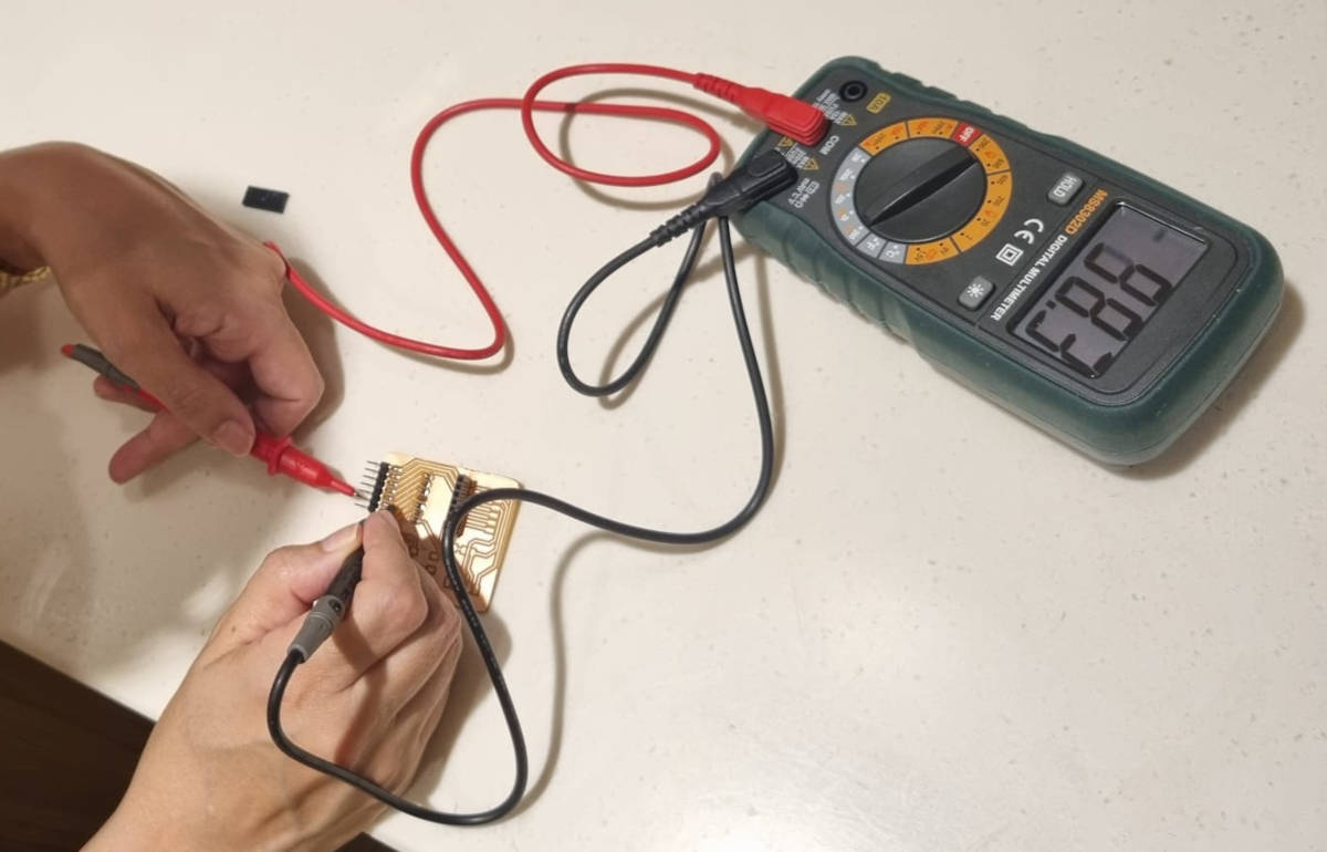
When the board was ready, I sanded the borders and the interior with fine sandpaper being careful to no tear the Copper. After I looked with a microscope that the paths were well defined. I found a bit of movement in the Drill of the holes, it seems that the board moved a little bit, there was a path that looked critical and had to make sure with the multimeter the connection was not lost between the path and the trace.
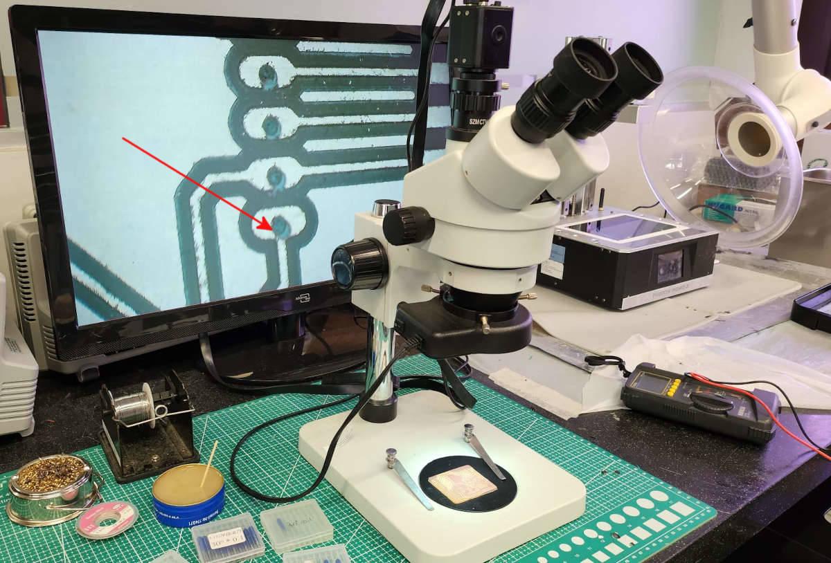
I checked with the Multimeter for path continuity, but it wasn't a major problem. I checked all the paths and all have continuity
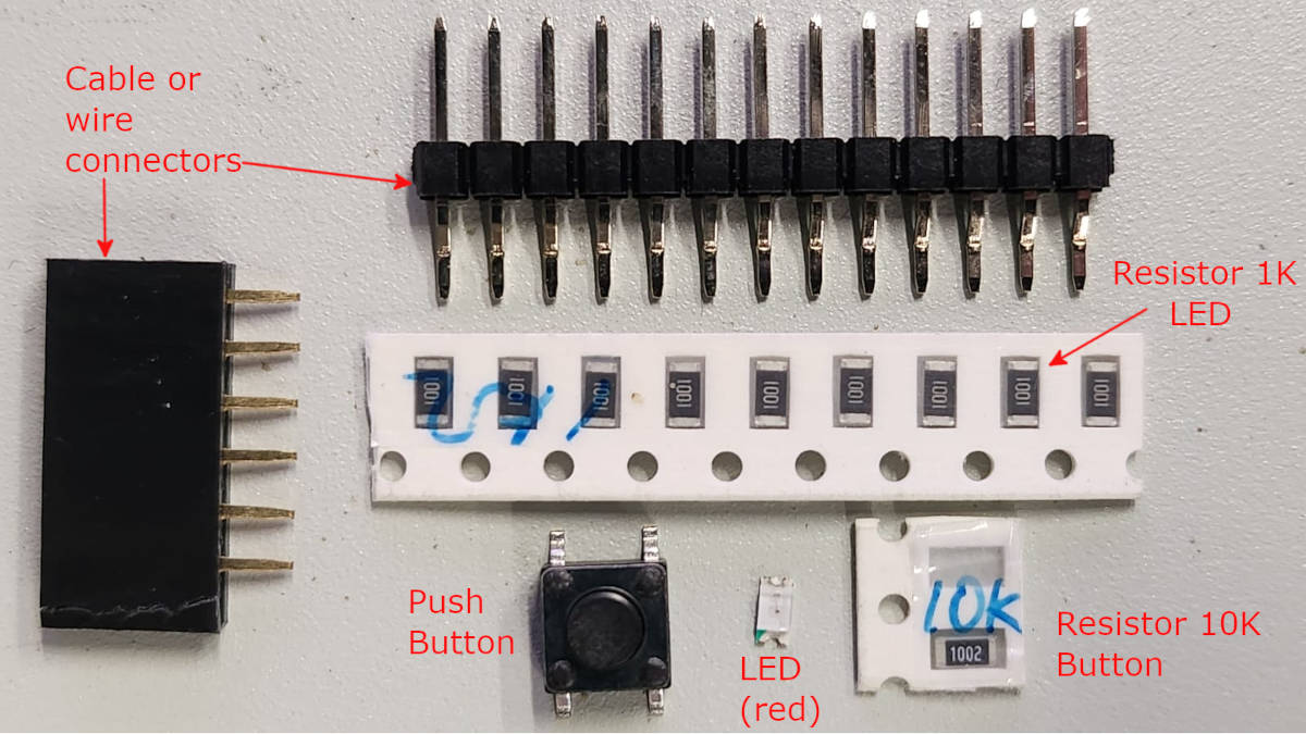
-Soldering the parts
- Cable/wire connectors
- A push button with Resistor 1002 (10K)
- A Red Led Light with Resistor 1001 (1K)
- The Microcontroller can be connected and disconnected
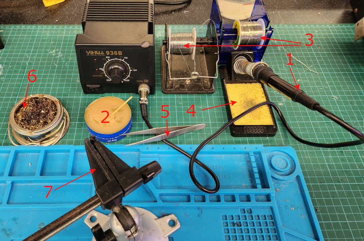
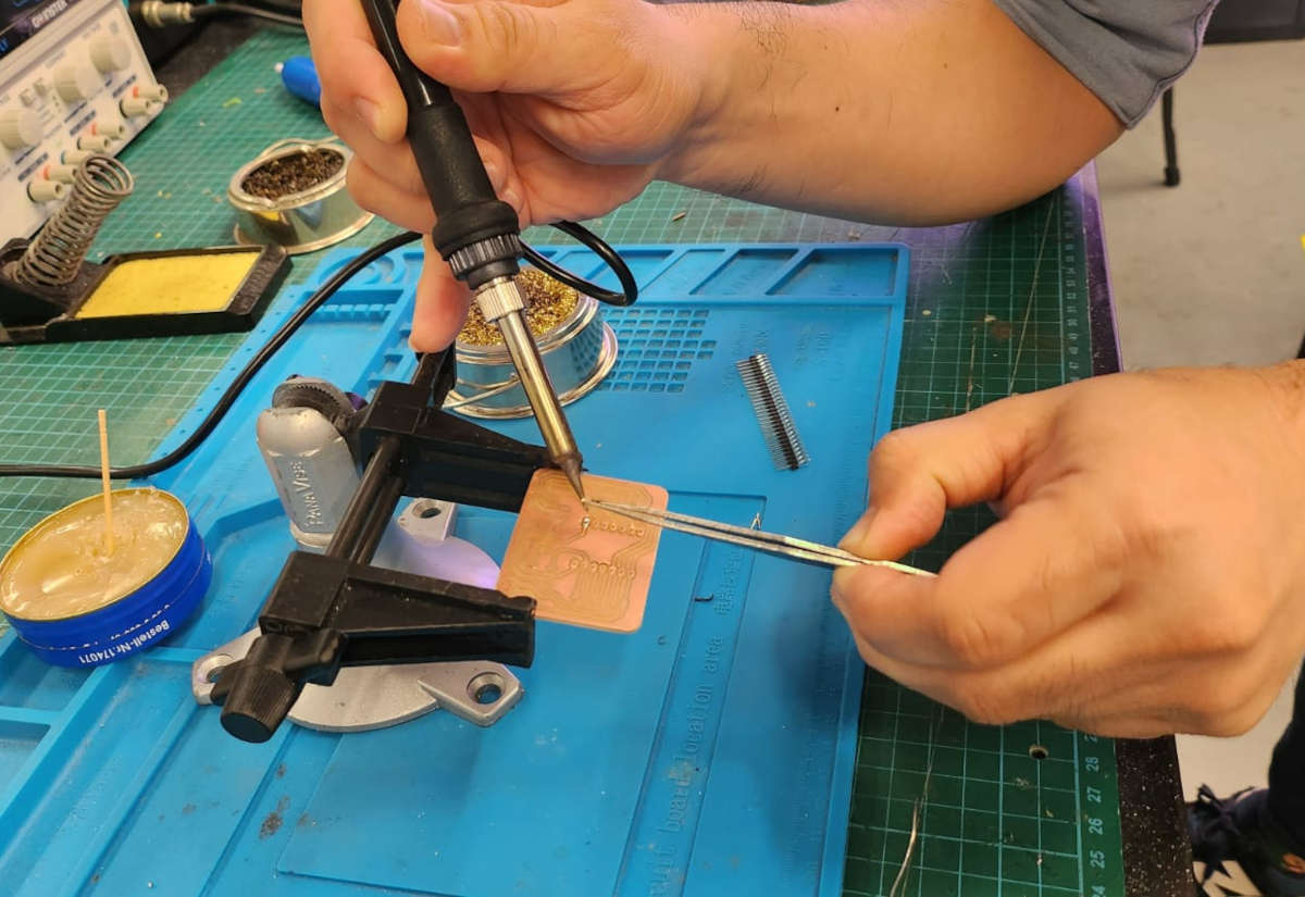
-What we need to do the soldering
- Soldering Iron (set to a temperature not higher than 230 C)
- Solder paste to clean surfaces and improve adhesion
- Silver Wire
- Wet sponge to clean the tip of the iron
- Tweezers, to hold small components
- A metallic spiral sponge to clean the tip of the iron
- Adjustable helping hand (if possible)
- A magnifier glass to see the very tiny details (we didn't have at the Lab)
For the Microcontroller connection I did each Pin connector separately, I took them out from their case, this was a big error being the first PCB that I made, Steven our instructor can do it, as he has a very steady hand and experience…not us, it took me very long to do each pin and they were in total (14) when the Silver melted the position of the pin changed and it was very difficult to align them.
In the end, all were a bit misaligned and not very strong which was bad as they suppose to be strong enough to stand the changes between different microcontrollers.
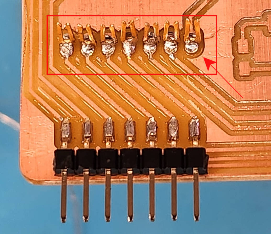
Next time I will do all of them at the same time not taking them out of the plastic case
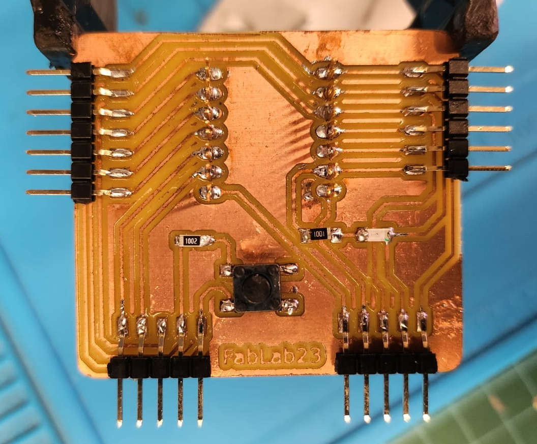
The rest of the soldering was a bit “easier”. Before soldering the Led light was very important to identify the ground and the 3V3 correctly, there was a green point marked in the light showing the direction of the Ground.
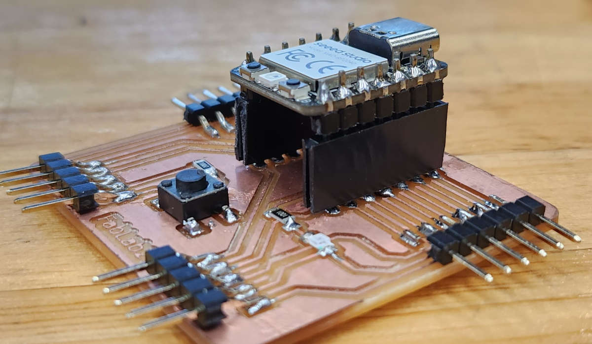
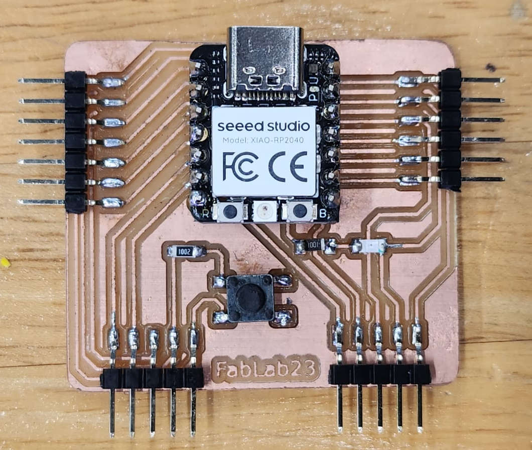
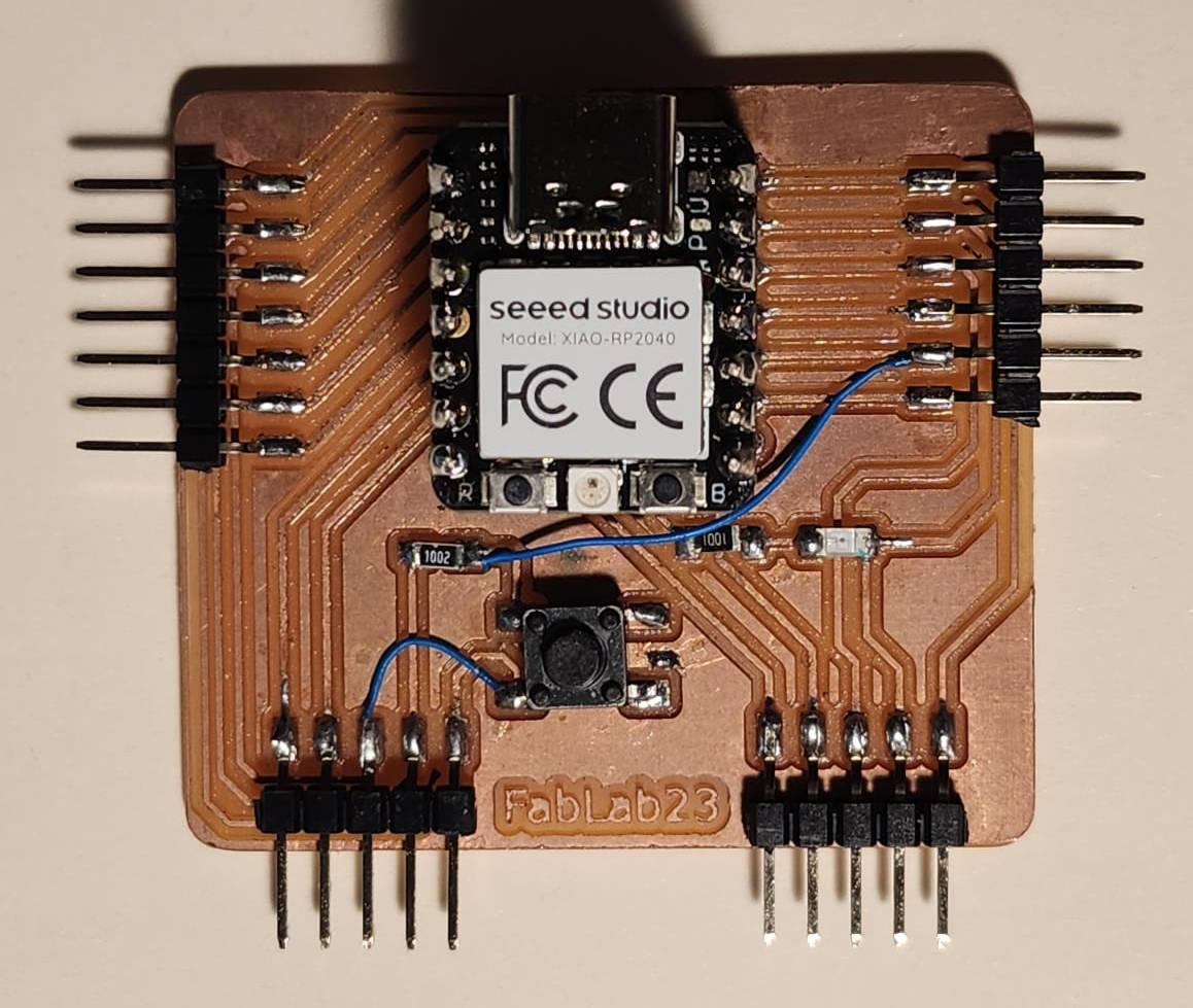
This is the final Board without the Microcontroller and with it.
|
|
-Programming the PCB and a fixing detour
It was time, I checked again all the paths and pins with the Multimter to make sure the paths and connections were correct. All tip-top!
So I sat in front of the computer and opened Arduino and the program example for turning on the led from the Arduino examples
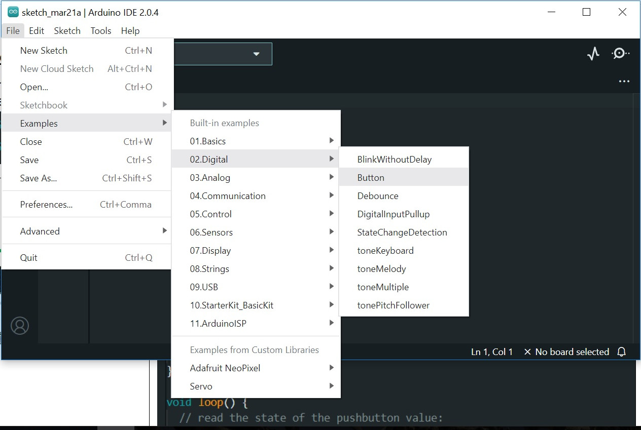
Then I looked for the Pin where the Push Button was connected…and surprise! The button was not connected, I had the board layout wrong!!!!
I regretted so badly not checking well the connections and that I didn't use a simulator to see if the board was well connected. Ok, then I had to find the error.
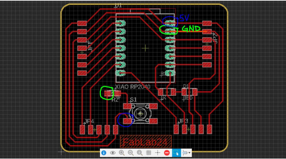
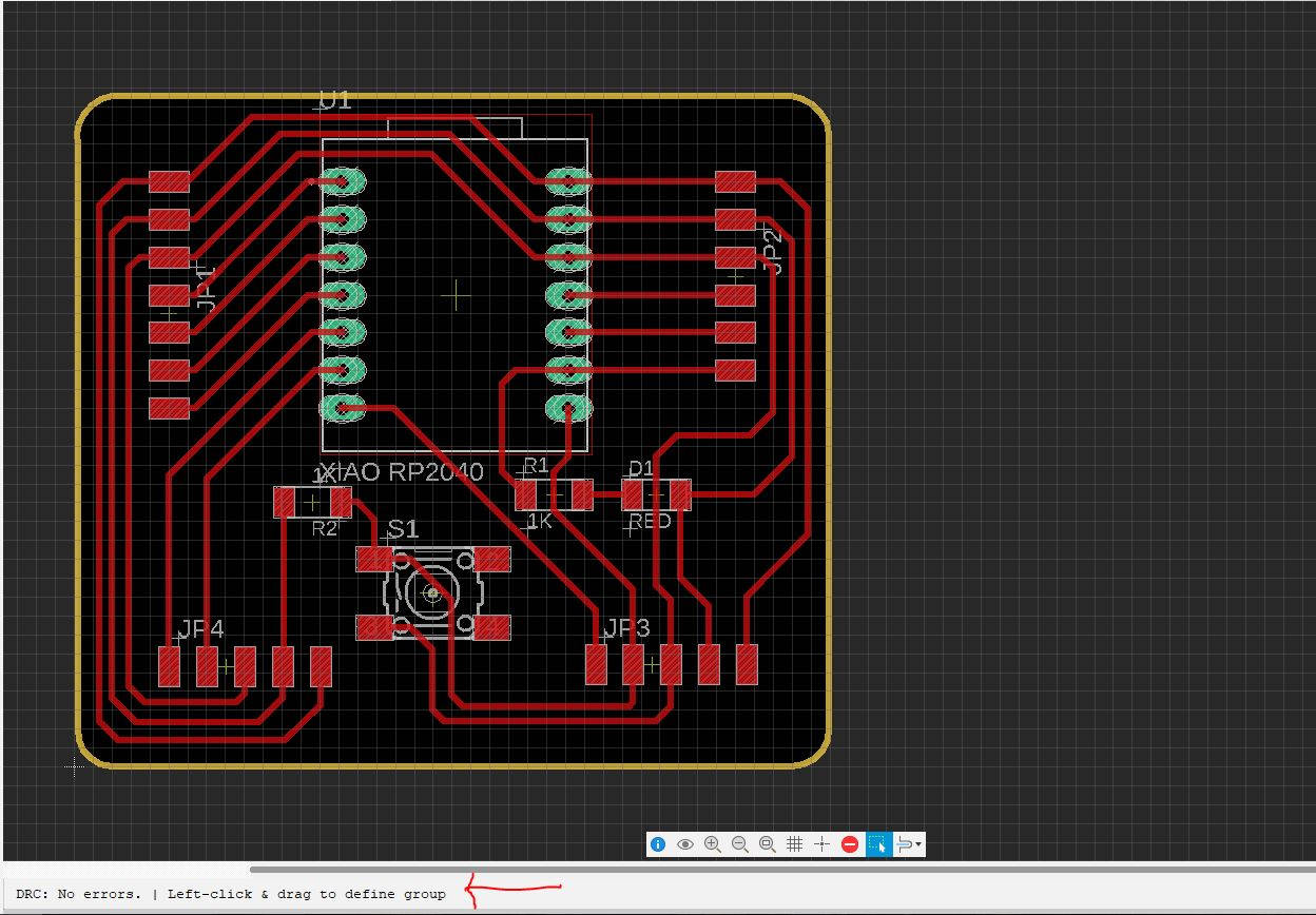
I opened Eagle-Fusion 360 and checked the Board design, I could see there that the Push Button didn't have a connection to a “data” Pin, it had a connection to the 5V Pin and Ground Pin only.
Then I opened the schematic design to see what was the problem with the connections, first accidentally named the wire connection VCC which is 5V, then I didn't do the connection to the Data Pin.
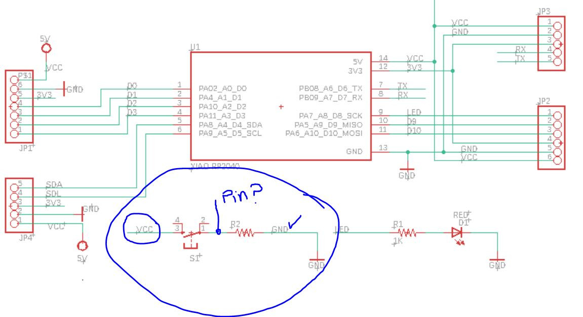
I had to fix the error in the schematic design so I could do the proper path trace in the board layout. I changed the connection to 3V3 and assigned the Pin D7 or RX for the data.
I checked with ERC that everything was well connected before going to the board layout. There were error messages that were expected: no value for the JP pins as they didn't have anything connected, and the 5V connected to VCC, this was on purpose.
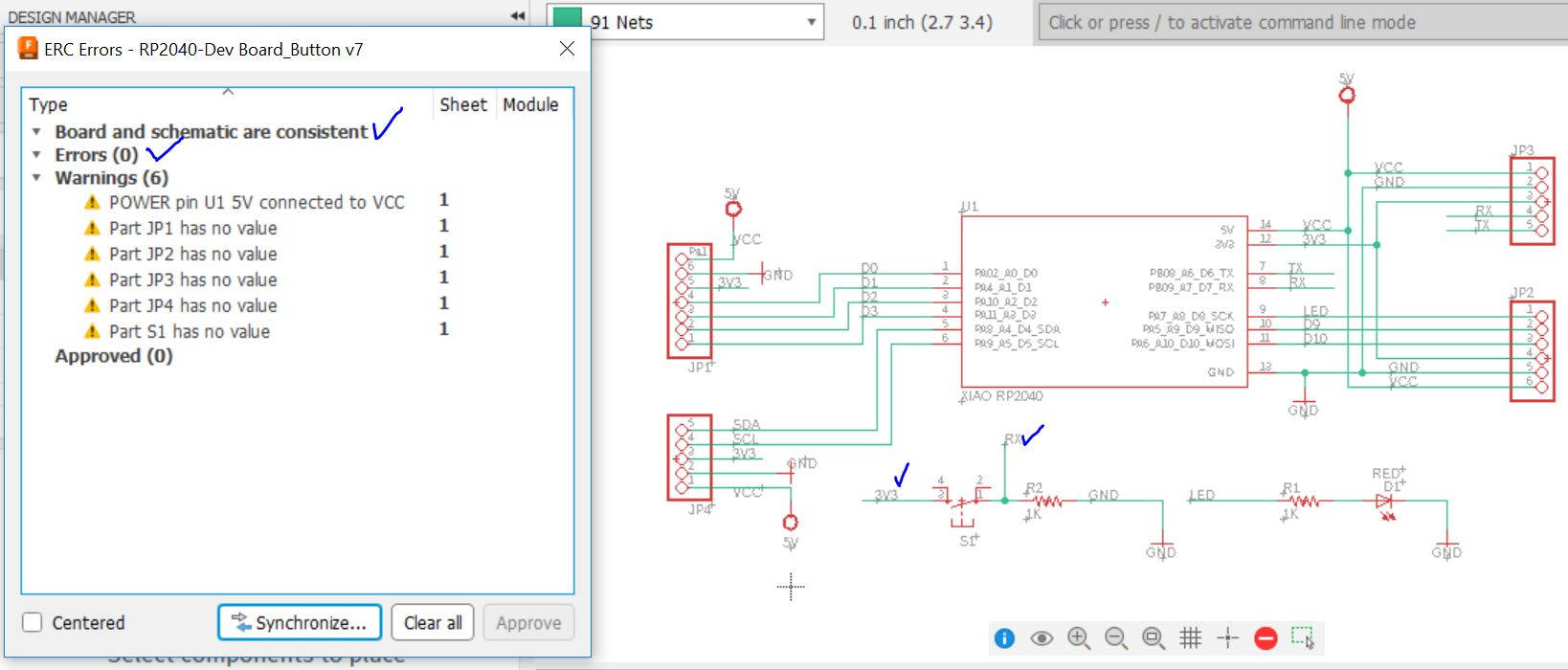
I went to the Board Layout and made the correct traces, and run the DRC to see if there were connection problems and it was clear. So the board design was fixed.
-Fixing the Board I already have
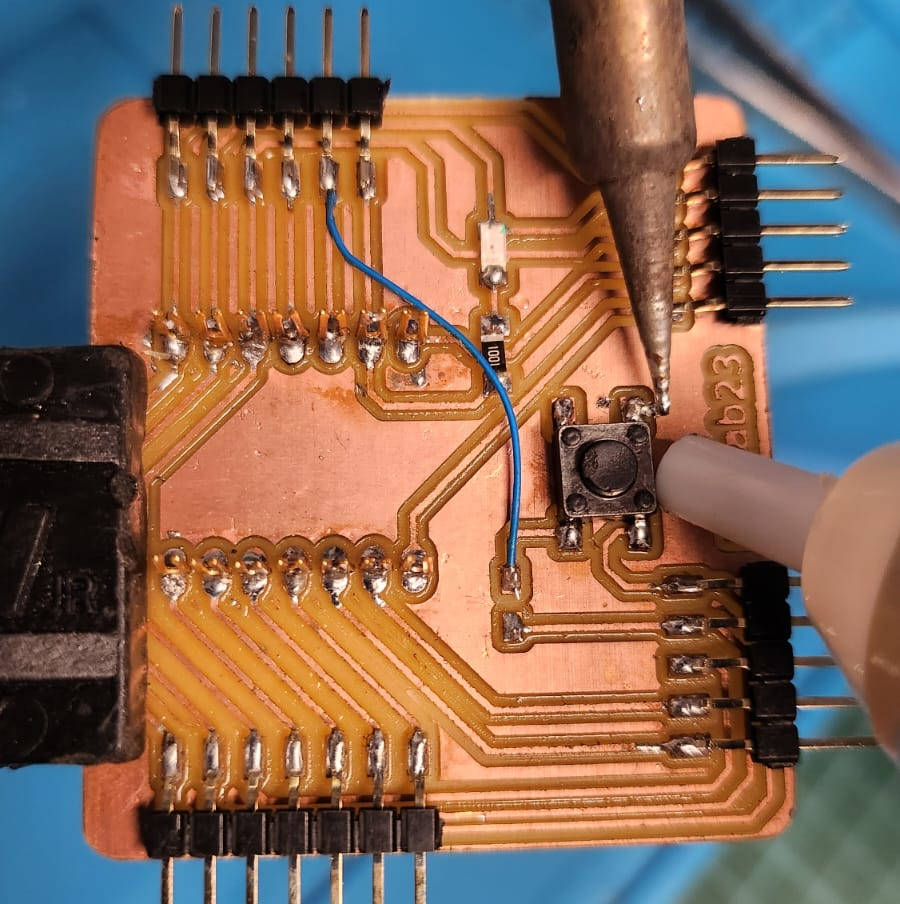
This was an opportunity to try to use the board I did before without making a new one. As the connection to 5V was wrong I had to take out the 10K Resistor cutting this connection.
As the Microcontroller has a built-in Transistor of 3V I just had to make it available through the programming.
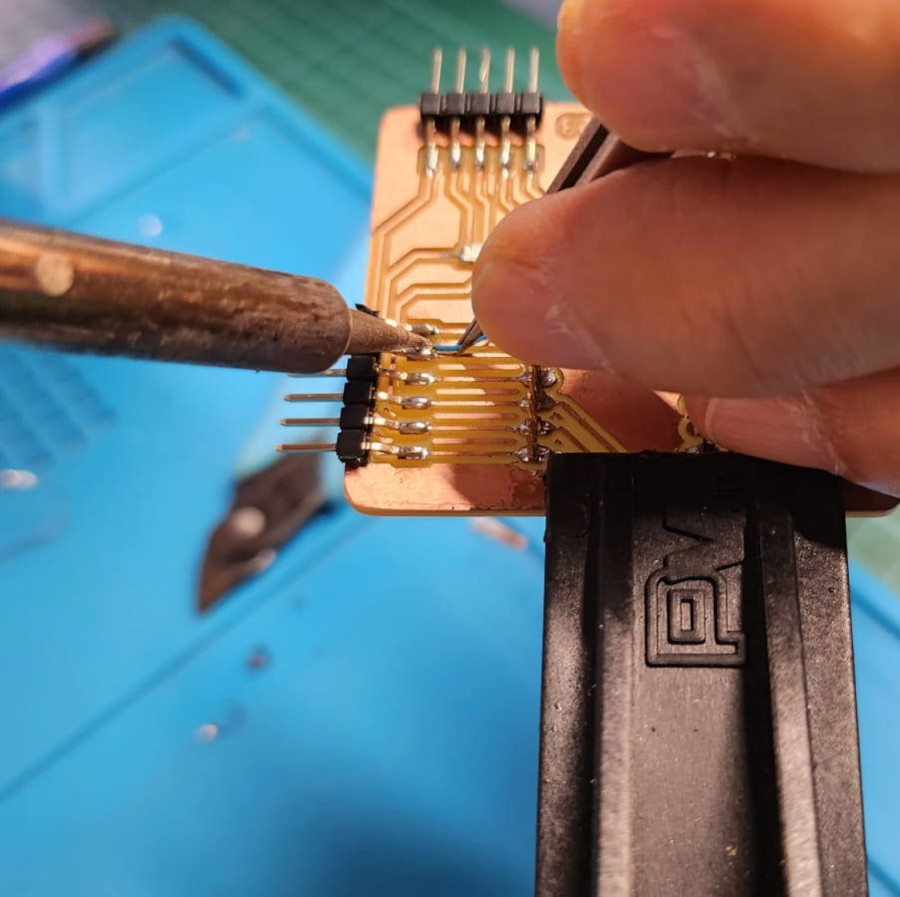
And lastly, with a Jumper (wire) I had to connect to an available Pin for the data
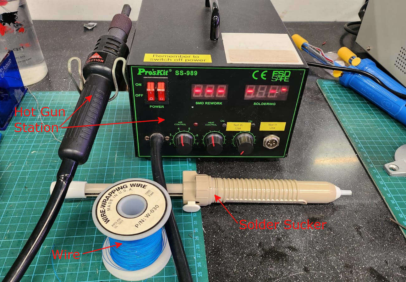
Equipment:
Steps:
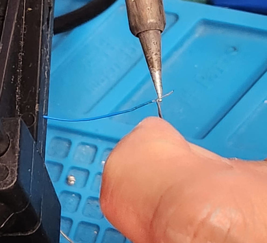
- Prepare the Wire-wrapping, pill both ends, and cover the wire with Silver
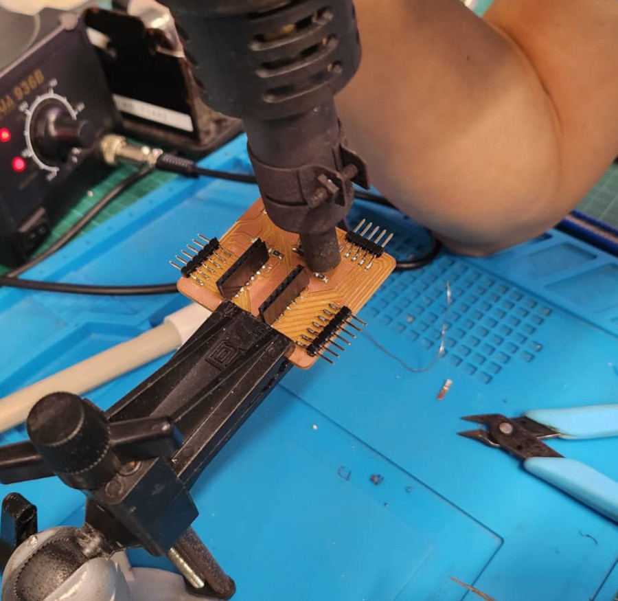
- We blew air with the Hot Air Gun to the resistor connections to take it out. Then with the Solder Sucker we took out the excess Silver off the board.
- We can use the Solder Sucker to clean any silver we may have extra in the board
- Lastly, we solder the Wire from the push button to an available Pin.
|
|
|
|
-Programming
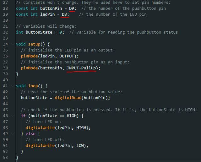
I open again the example file for the Button in Arduino, change the value of the Pins accordingly to my board design and very important I able the use of the internal Resistor of the Microcontroller just typing INPUT-PULLUP
This Programm allow us to press and hold the button to light on the LED light, once we stop pressing the light turns off
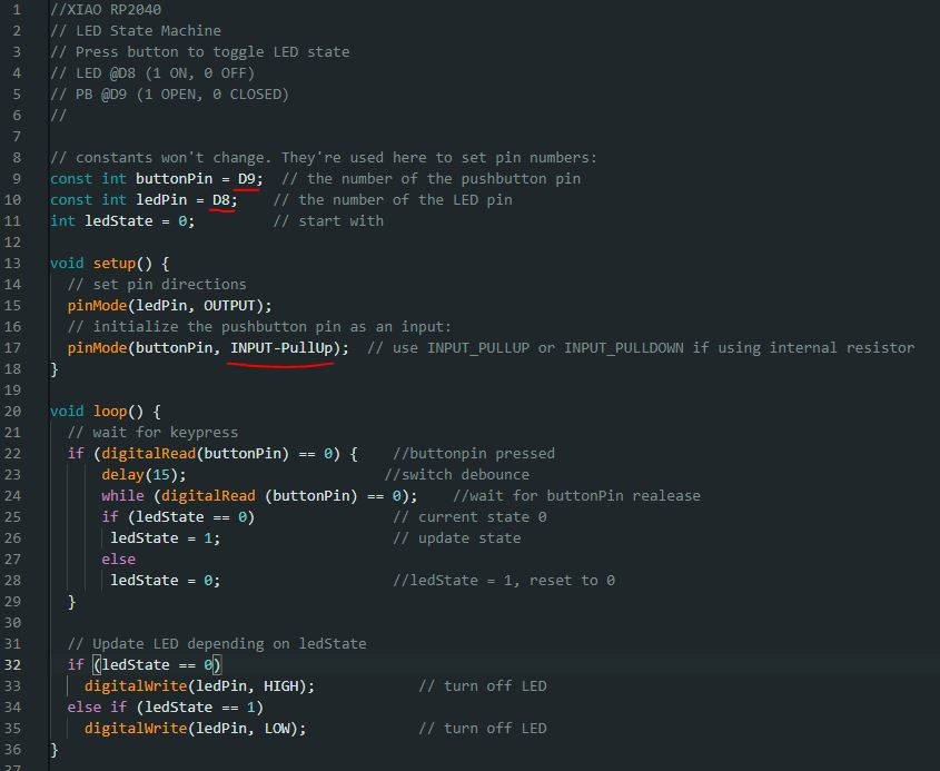
But I want to push the button once to have the light ON and push it again to have the light OFF, this requires other programming
-Learning outcome
It was a difficult week, as we have to do the PCB production and the programming. The milling stage was quite easy for me, I followed the rules we have in the Lab for it and they work quite well.
Then the soldering was a more complicated stage, but somehow I managed to get the Board working.
The problems started to be difficult to solve when I realized that the board design was wrong.
I redesigned the board in Eagle, but I challenged myself to repair the one I already had. The problem was I had the Voltage connection wrong in 5V and I didn't have a “data” connection.
I took out the Resistor from the board and programmed the Microcontroller, and added a jumper to an available Microcontroller Pin. With this change, the board and the programming were working quite well.
But then I realized at the Asia meeting, I didn't change the connection to 3V, so I decided to go back to the original plan, put back the resistor, cut the 5V connection, and put another Jumper to 3V…and now the board is not working and the week is already finished.
What I would’ve done differently?
I would've used a simulator so I would've found the trace error early. That is the main take.
-Update: DEBUGGING
- I started to check that all the paths were connected to the microcontroller with the Multimeter continuity, they were.
- Then checked that the light was getting Voltage
- I checked the light was working lighting, download the Blink code and it didnt work
- lastly I checked the connection between the Resistor and the light...surprise it wasnt connected. While doing reparations to the board, I supose when I blew hot air to get some pieces appart the transistor moved of its place and lost contact
So I (we counting Steven) found the problem with the board, I fixed it and now is working again. The codes for the lights are the same.
LINKS TO FILES
- Board in Fusion 360 (version 12 and version 16) HERE
- PNG trace template for milling HERE
- PNG drill template for milling HERE
- PNG outline template for milling HERE
- G-Code template traces HERE
- G-Code template drill HERE
- G-Code template Outline HERE
- Arduino Code for button HERE
- Arduino Code for button tuggle HERE