dummy
10.MACHINE BUILDING
Our team has decided to built an "XY Wall Plotter Robot" that utilizes G-Code software to control the robot's drawing of images. We drew inspiration from another CREATOR on the internet and eagerly took on the challenge of constructing this machine.
HERO IMAGE AND VIDEO
ASSIGNMENTS
Gropup Assignment
- Design a machine that includes mechanism, actuation, automation and application
- Build the mechanical parts and operate it manually.
- Document the group project
Individual Assignment
- Document your individual contribution.
GROUP ASSIGNMENT
Throughout the project, we faced various unique challenges, such as designing the machine, 3D printing the parts, working with electronics, and programming the software to set the Robot functions and generate the images.
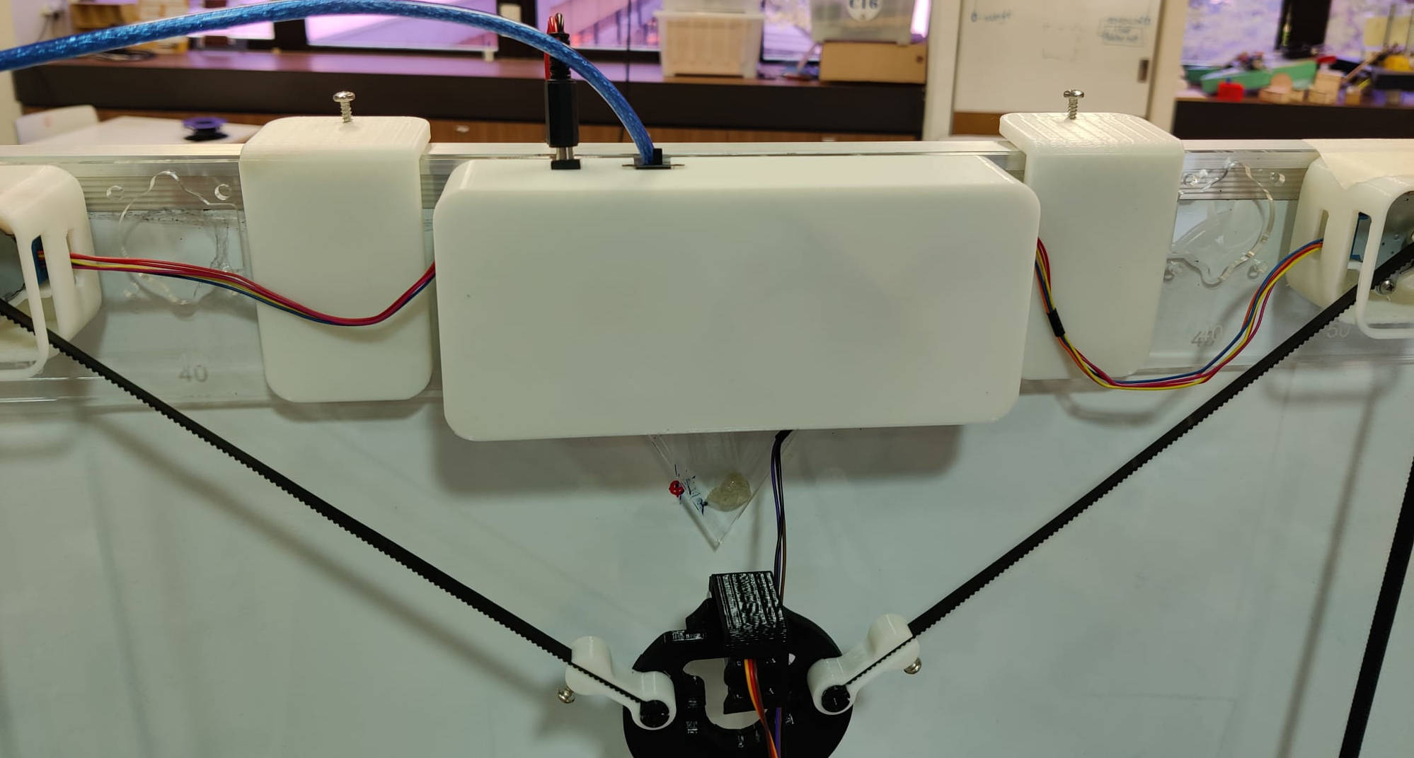
One of our key goals was to make the parts easily disassembled and compacted, which led us to design the parts in 3D. The size of the drawing area can be changed relocating the motors in different positions that are set at the Plotter base structure. This approach allowed us to create a more versitile and practical machine.
For further details on the group assignment, please refer to the link provided HERE , which includes a comprehensive overview of the CNC machine operation.
INDIVIDUAL ASSIGNMENT
In the group assignment, I contributed in the following ways:
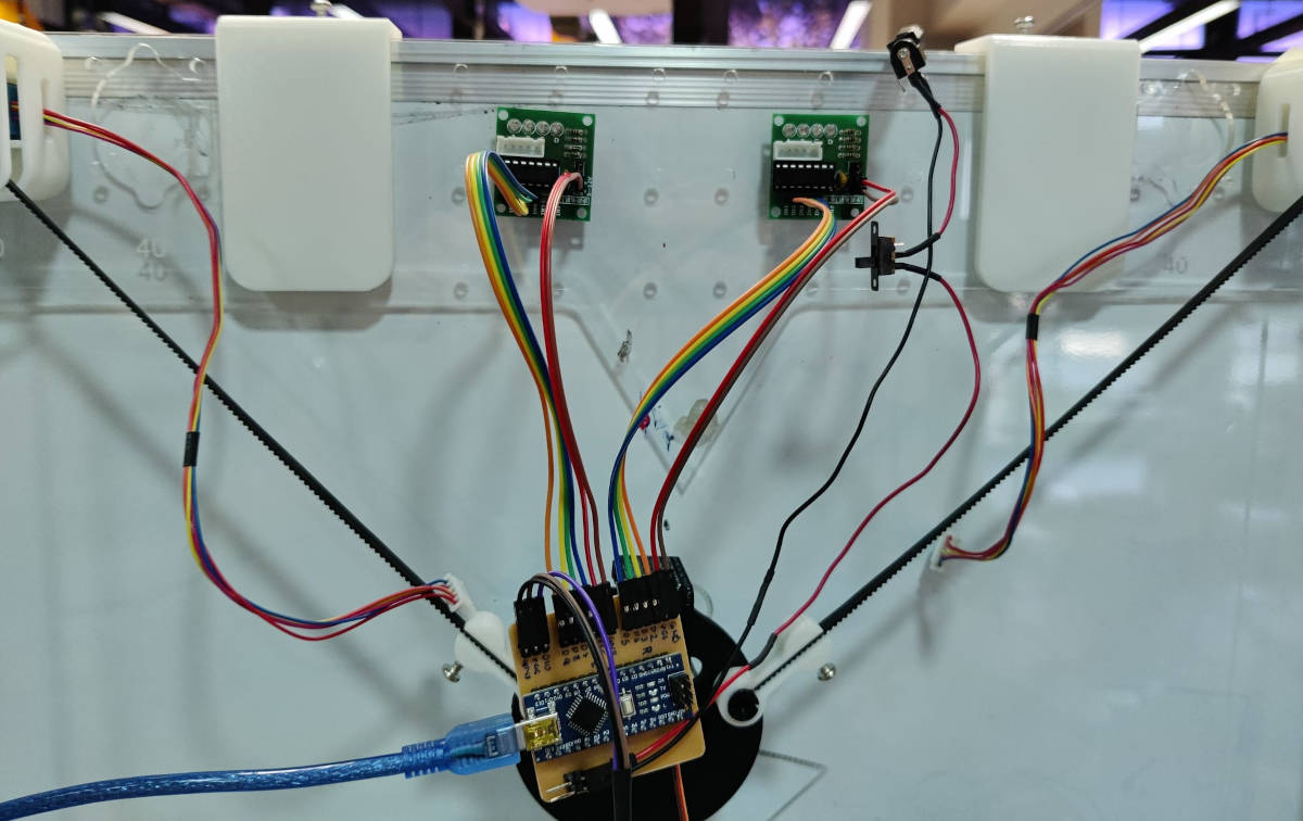
- Assisted with setting up the machine by connecting the various cables. This was a challenging task as there were many cables to connect, and it was easy to get confused.
- Due to the complexity of managing the cables, we decided to create our own Printed Circuit Board (PCB) to simplify the cable connections. We also opted for a minimal Microcontroller. For this purpose, we chose an Arduino Nano as it supported 5V. So I was leading the design and making of the PCB.
- In the group project, I was responsible for coordinating all the documentation. This involved compiling and organizing all the information in a logical and structured manner and ensuring it was uploaded onto the group page.
1. Setting Up
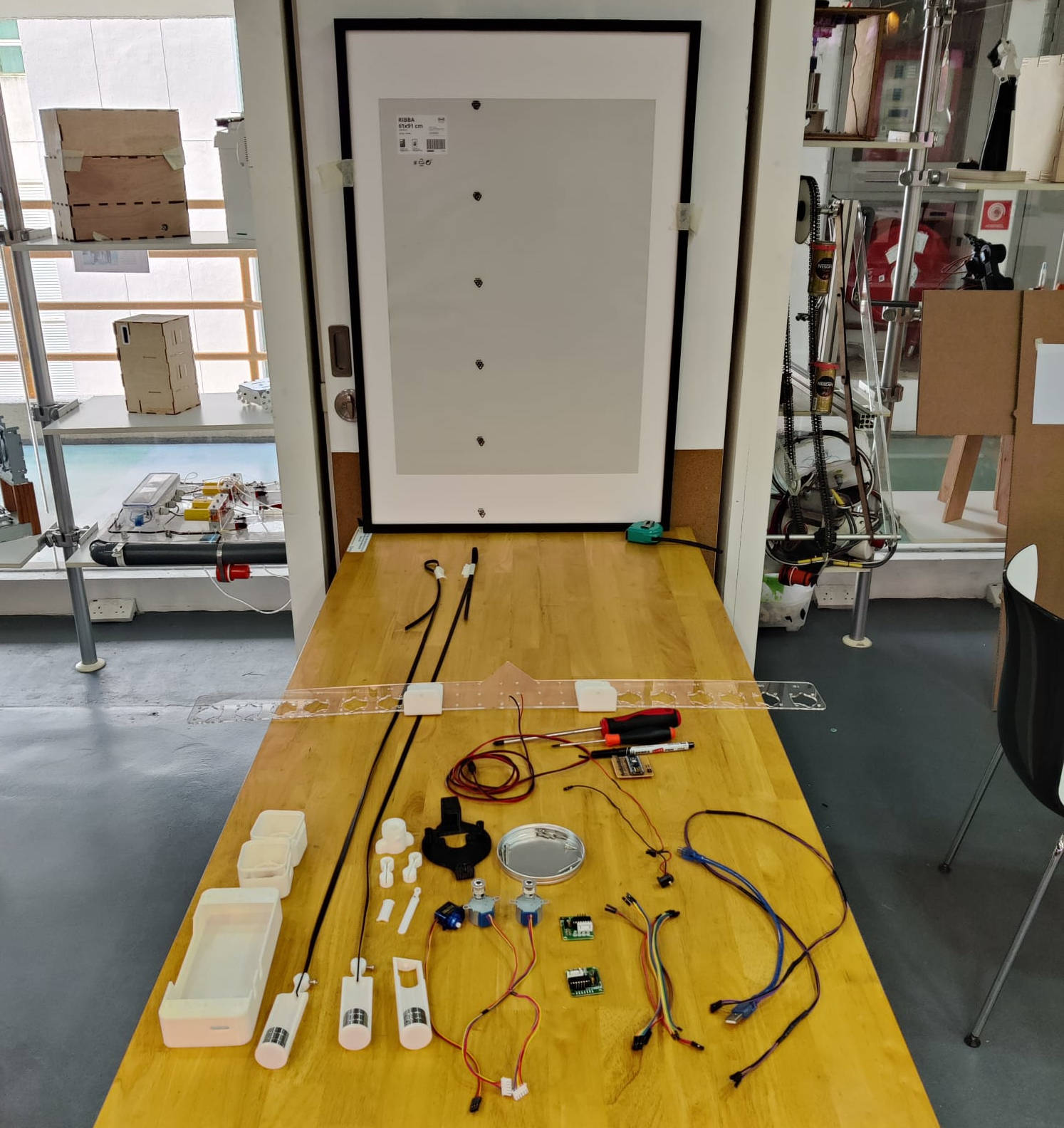
As we have never worked with Stepper motors we did a “quick” installation of the motors to test the library code
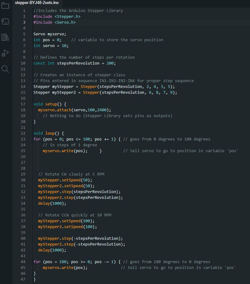
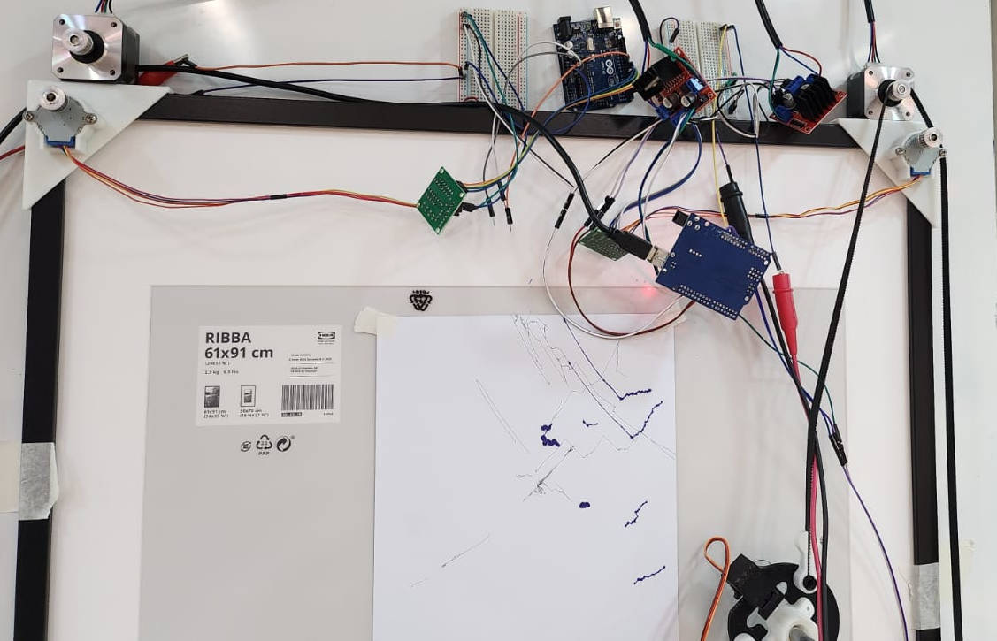
We used the bread board to do this connections faster, and left to a later stage the board connection and cable management of the final product.
When it comes to basic movements, we can rely on the power supply from the computer. However, for a more dependable power source of 5 volts, later when putting the machine together, we opted to connect the machine to a Bench Power supply. This was especially necessary since the motors we were using consumed a significant amount of current.
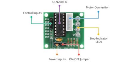
To properly manage this high current consumption and the comunication with the board, we needed to connect the motors to a Motor Driver ULN2003. The Motor Driver works by taking the low current control signal that comes from the Microcontroller and amplifying it into a higher signal that can effectively drive the motors.
2. PCB Design and Production
After conducting the machine test, we found ourselves grappling with an excessive number of cables and connections. In order to simplify the process, we devised a solution to create our own PCB board, allowing us to eliminate the need for the Bread Board.
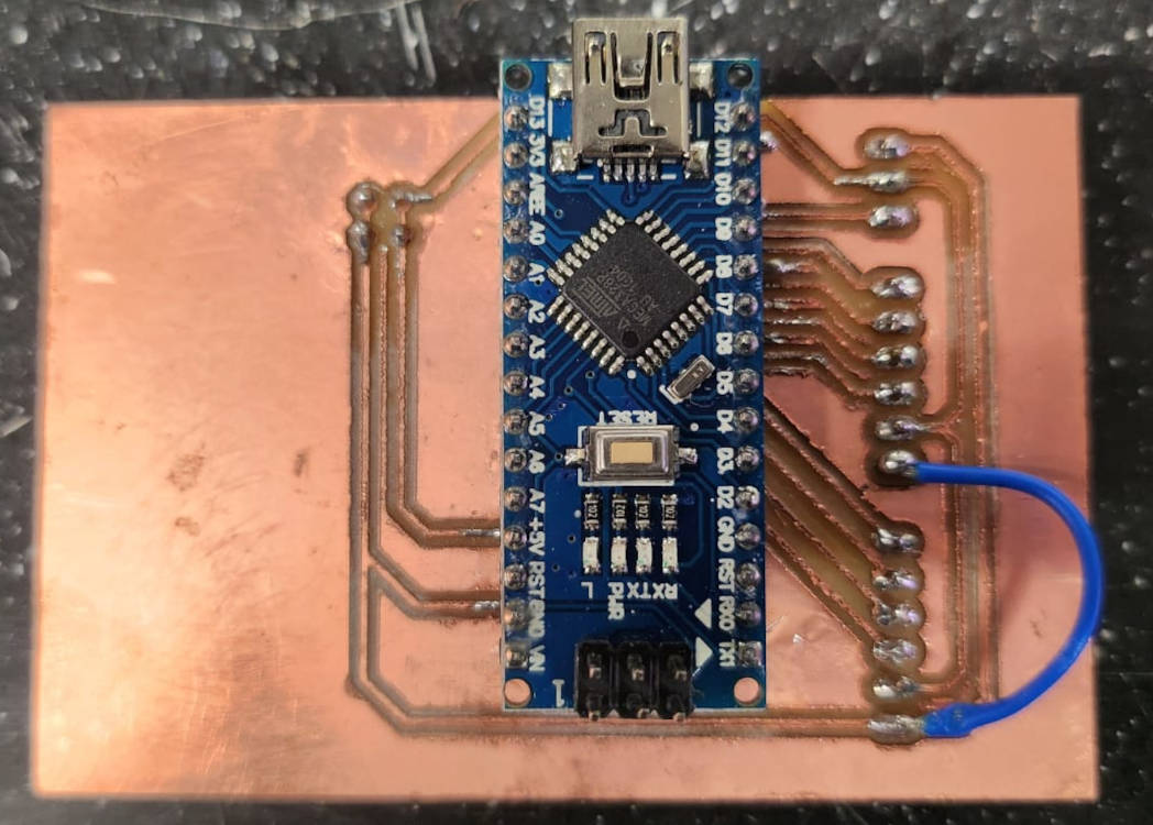
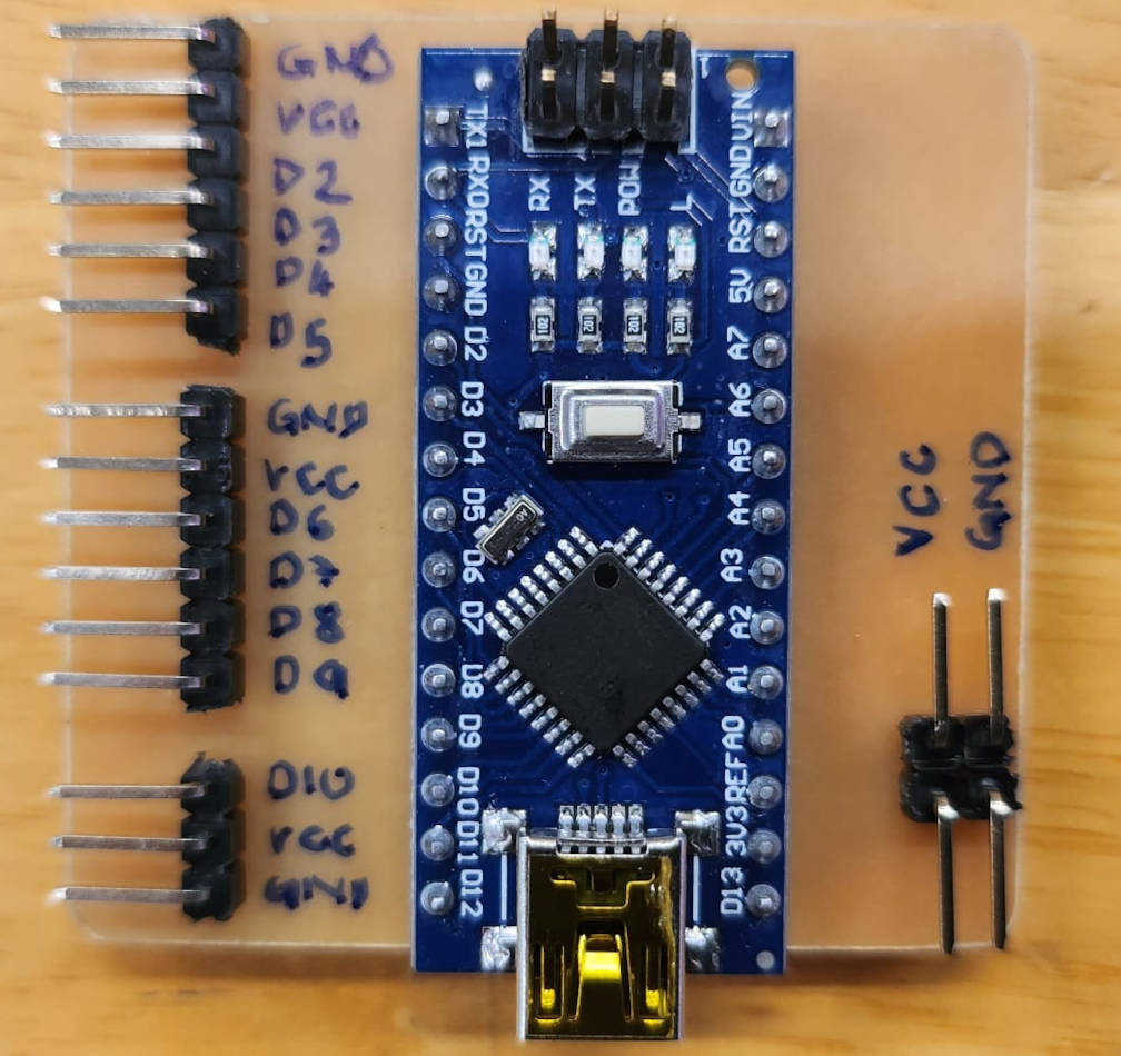
The newly-designed PCB board also features a 5V power input that accommodates an adaptor plug. It seamlessly connects to both the motor drivers and the servo motor through soldered pins.
"The PCB board has been equipped with a custom-designed casing that effectively conceals both the cables and microcontrollers."
We encountered several issues during the PCB production process. Initially, the milling process was not completed accurately, causing incomplete pathways. Additionally, we neglected to check the microcontroller before soldering it to the board, leading to the discovery of a defect and ultimately resulting in damage to the board when attempting to remove it.
The pathway widths were also too thin, exacerbating the challenges we faced. Furthermore, the design called for the microcontroller to be placed on the top, which made it exceedingly challenging to perform the soldering process
|
|
Solutions:
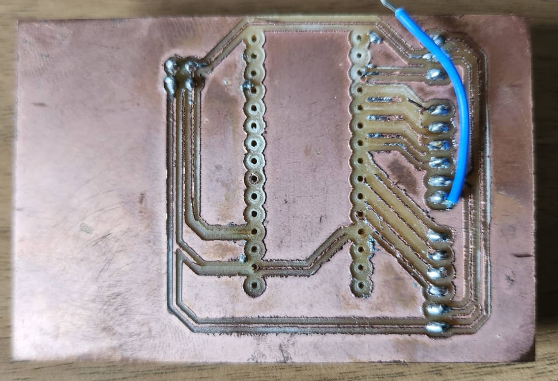
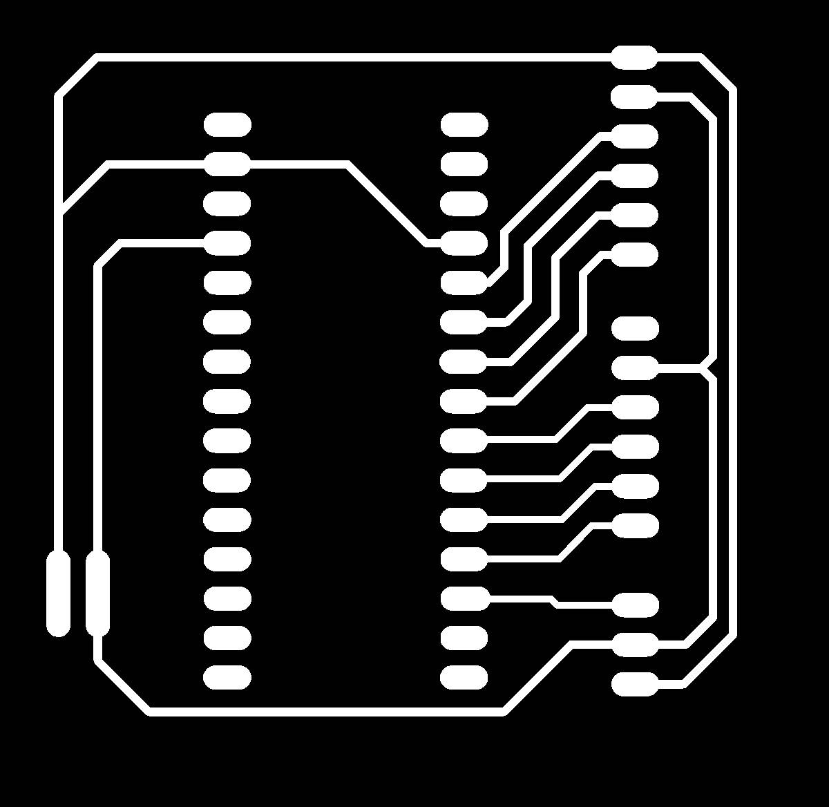
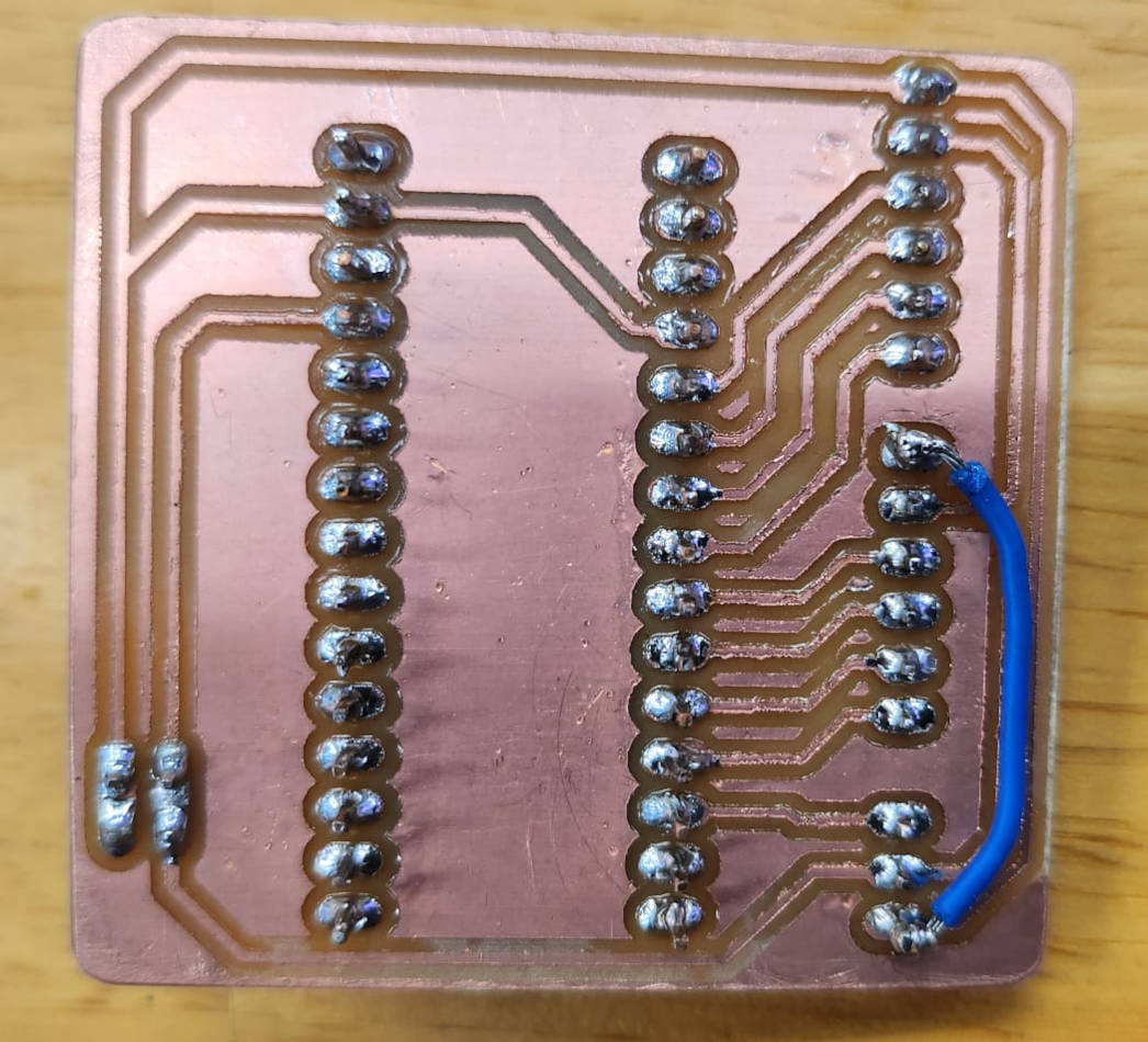
- Designing the paths to be printed in the "back of the Board" so we could solder the parts in the back of the PCB, we could never solved the way to connect with a path the Ground of the Stepper motor in the middle, so later we connect it with a jumper. We made sure that the paths for the power and Ground were thicker as they will be conducting 5V.
- In the previous milling we used a V-Bit of 0.01mm 20 degrees, we changed to 30 degrees so the lines were a bit thicker, and made sure the bed surface was even.
- Of cousre this time we tested that the microcontroller was connecting with the computer and uploading the Arduino Sketches.
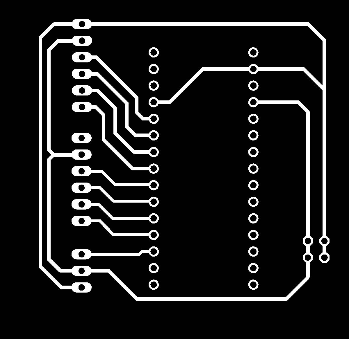
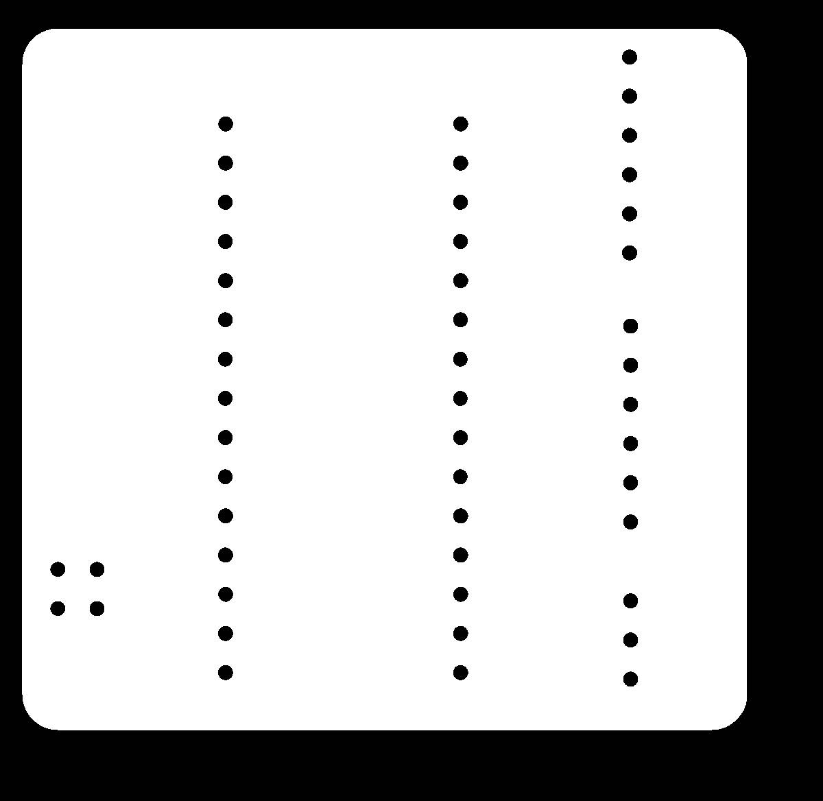
- And we solder the parts of the board at the back of the board, for this we had to mirror the PNG Images of the paths and the Outline generated from Eagle
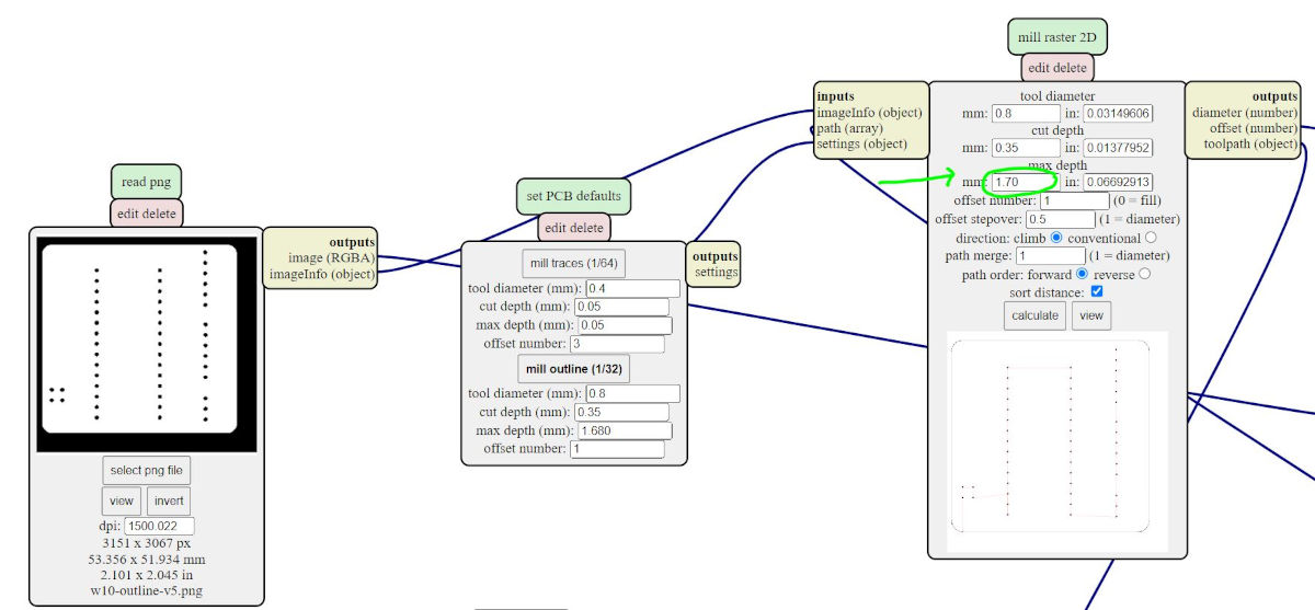
- And lastly, as the milling wasn't going through for the cutting of the outlines, we changed the settings to 1.70mm for the bit to go dipper, before it was 1.68mm.
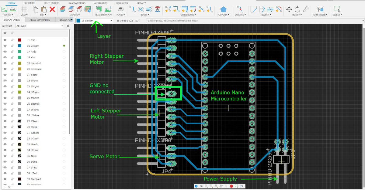
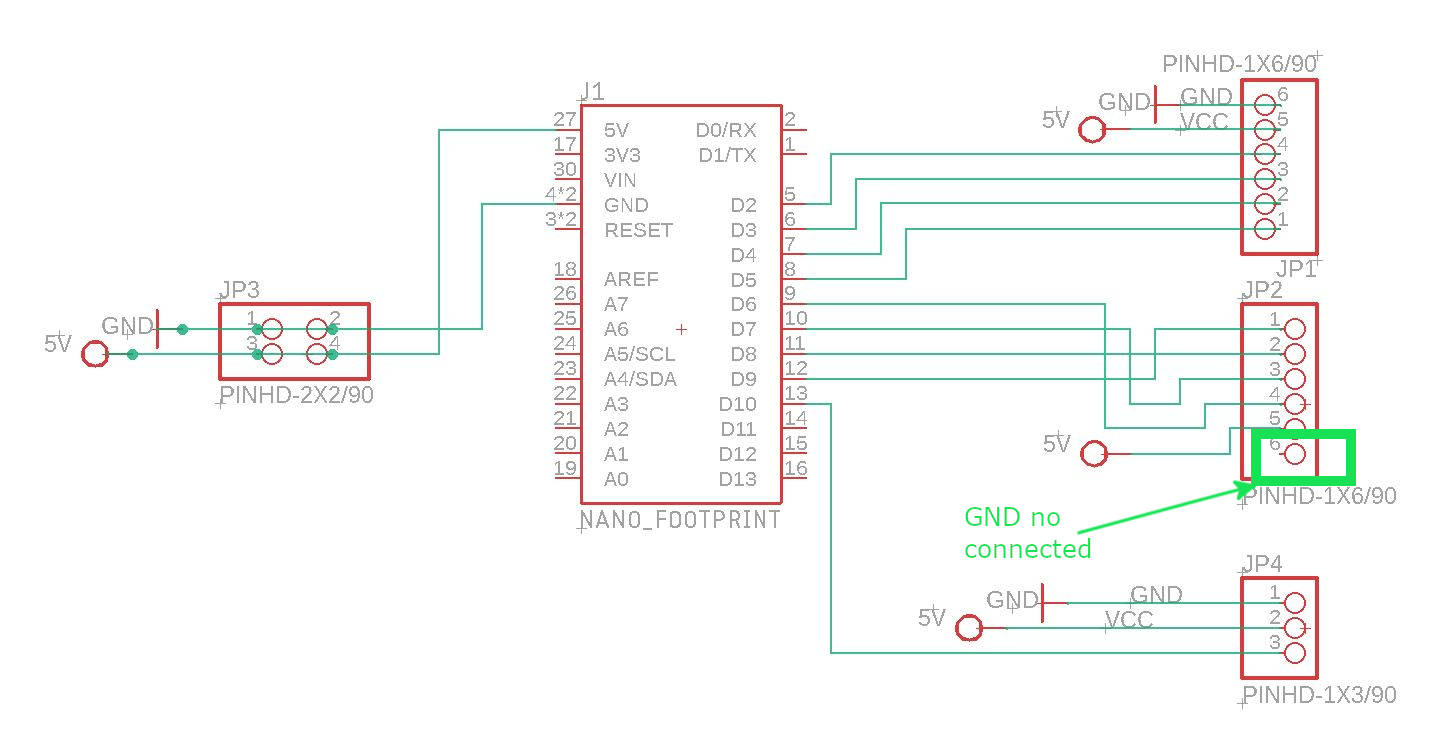
When running the ERC and DRC commands in Eagle the program told us we have a Ground in the system not connected, so we erased the connection to make it later with the jumper.
|
|
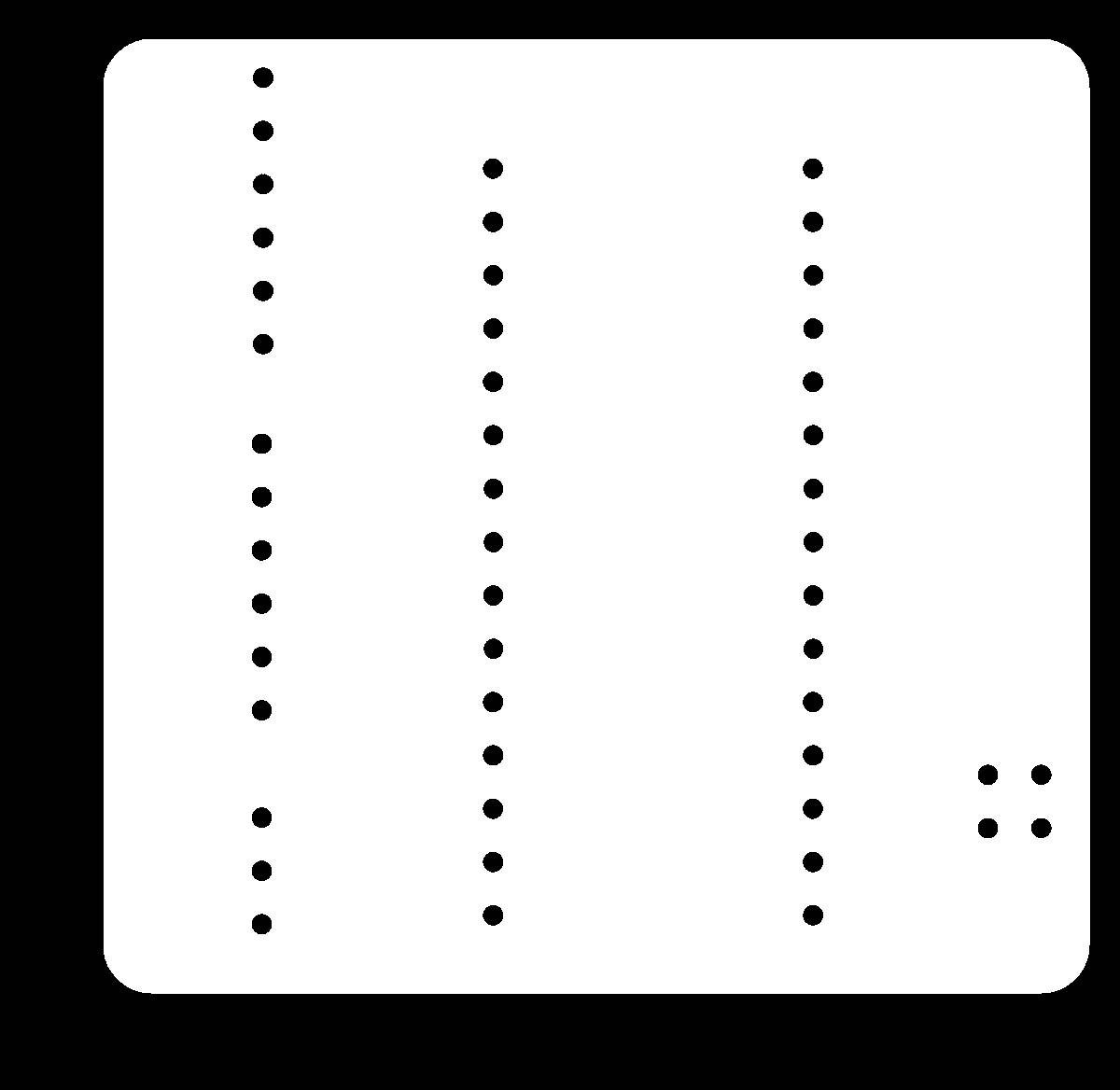
For the paths file, we did some corrections with GIMP, erase the drill holes, and made the paths for the microcontroller bigger, in the previous milling we ere left with very little copper and it was difficult to solder the pins of the microcontroller into the paths
|
|
This is the final board!
|
|
3. Reflections on the Group Assignment
Participating in the setup process allowed me to gain a more profound comprehension of the intricate cable connections needed for my final project's circuitry. This, in turn, provided me with insight into the electronic requirements of the project and how to enhance it by fabricating the PCB. The design and manufacturing of the PCB offered valuable hints that I can employ in upcoming projects. Nonetheless, creating PCBs is an arduous task that involves numerous steps requiring meticulous attention to detail, such as understanding the different parts and microcontroller, making proper connections, milling with precise settings, preparing the CNC workspace adequately, soldering, testing, and more. Although it can be stressful and disappointing at times, the gratification of witnessing our boards performing the intended tasks makes it all worthwhile.