dummy
7. COMPUTER CONTROLLED MACHINING
This week we were introduced to the CNC machine! Out FabLab has a “Versatil 2500 (8 ft x 4 ft) large-format CNC milling machine”. It can cut steel, wood, aluminum, plastic, and foam.
The CNC mill machine is operated by a computer in which we have programmed the way it should move to cut, through a G-code file.
As a result of this programming, we can reproduce the same outcome several times with high precision.
HERO IMAGE
ASSIGNMENTS
Gropup Assignment
- UComplete our lab safety training
- Test runout, alignment, fixturing, speeds, feeds, materials, and toolpaths for our lab’s machine
- Document our work on the group page and reflect on our page what we learned
Individual Assignment
- Make (design, mill, and assemble) something big
GROUP ASSIGNMENT
Working with the CNC machine can be overwhelming due to its size. The setup process is a lengthy one that involves working with multiple software programs before milling can begin
To start, we did some milling samples similar to the laser cut machine to establish the kerf and the machine feeding value. In our CNC machine, the kerf was 0. This value was crucial because in my individual project, I designed several joints and had to take the kerf into consideration while designing them.
You can see HERE more about the group assigment, where we see more in detail the CNC machine operation
INDIVIDUAL ASSIGNMENT
-Design Process
It took me a while to come to the final design, I wanted to do something that I could disassemble and needed at home.
My first idea was a lamp…not a good idea! As with the CNC works we have lots to sand after the milling, and this lamp ended up having lots of little parts, and the thickness of the material made it look chunky. More of a project for the laser cutter.
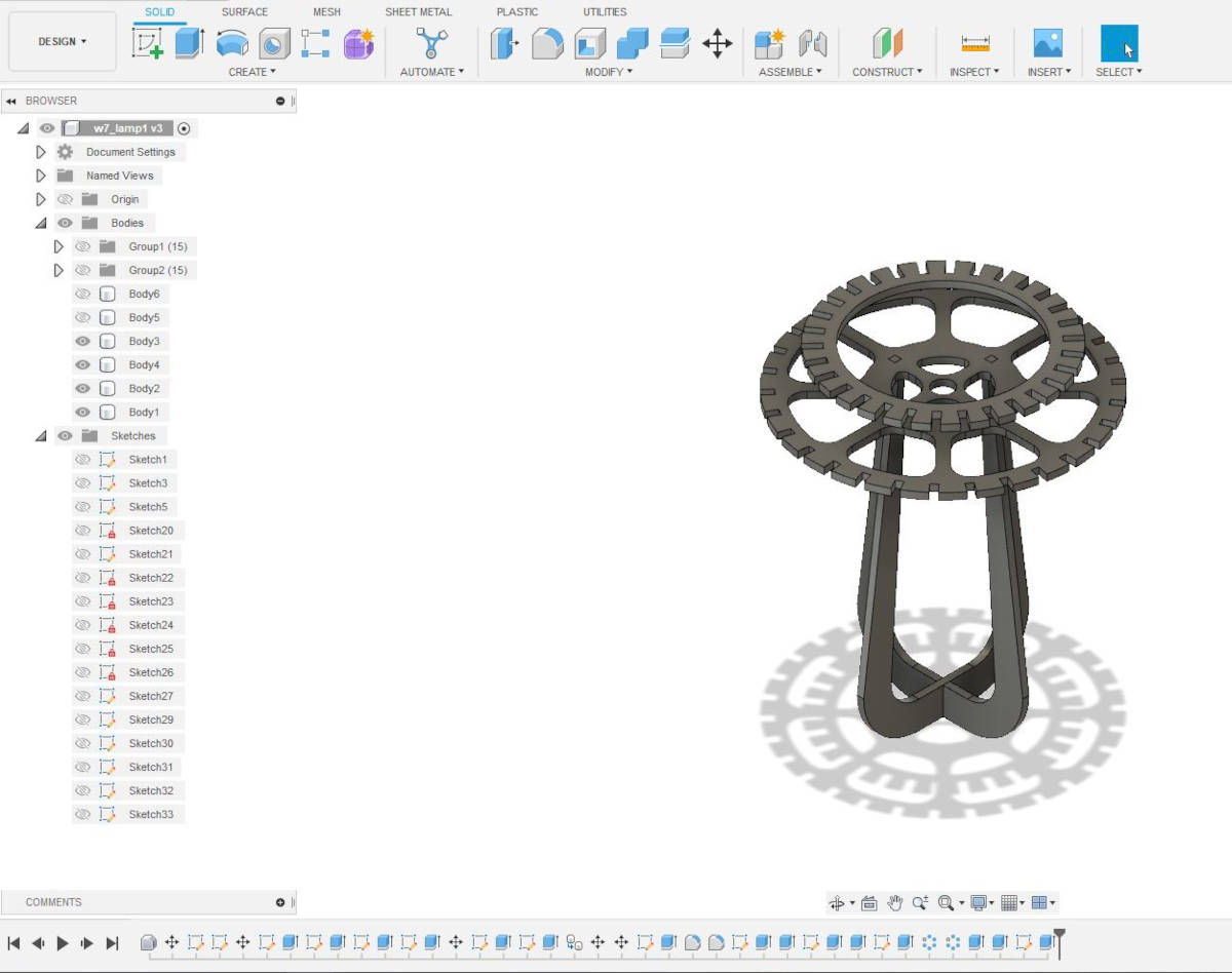
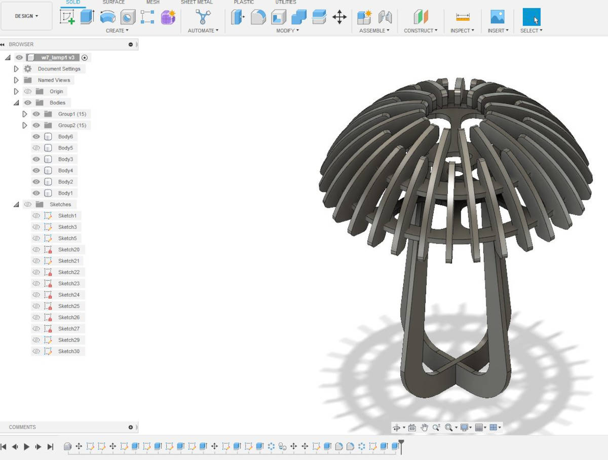
Making the lamp design took me two days as I am still not very “fluent” with Fusion 360 and it was very difficult for me to do the design parametric.
-Change of design
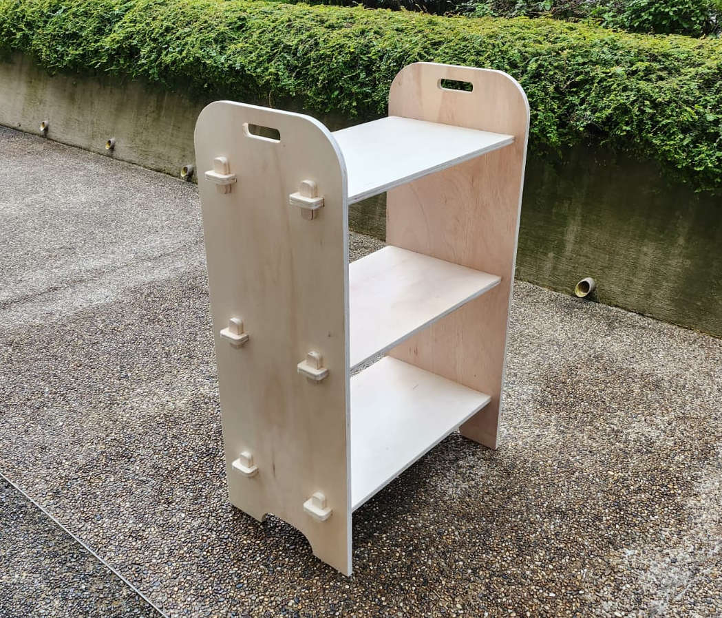
Then I started a new design, something more simple and doable with my present knowledge of the program. I designed a straightforward Bookcase without glue, screws, or needles. It should be possible to be taken apart, as we move constantly from places.
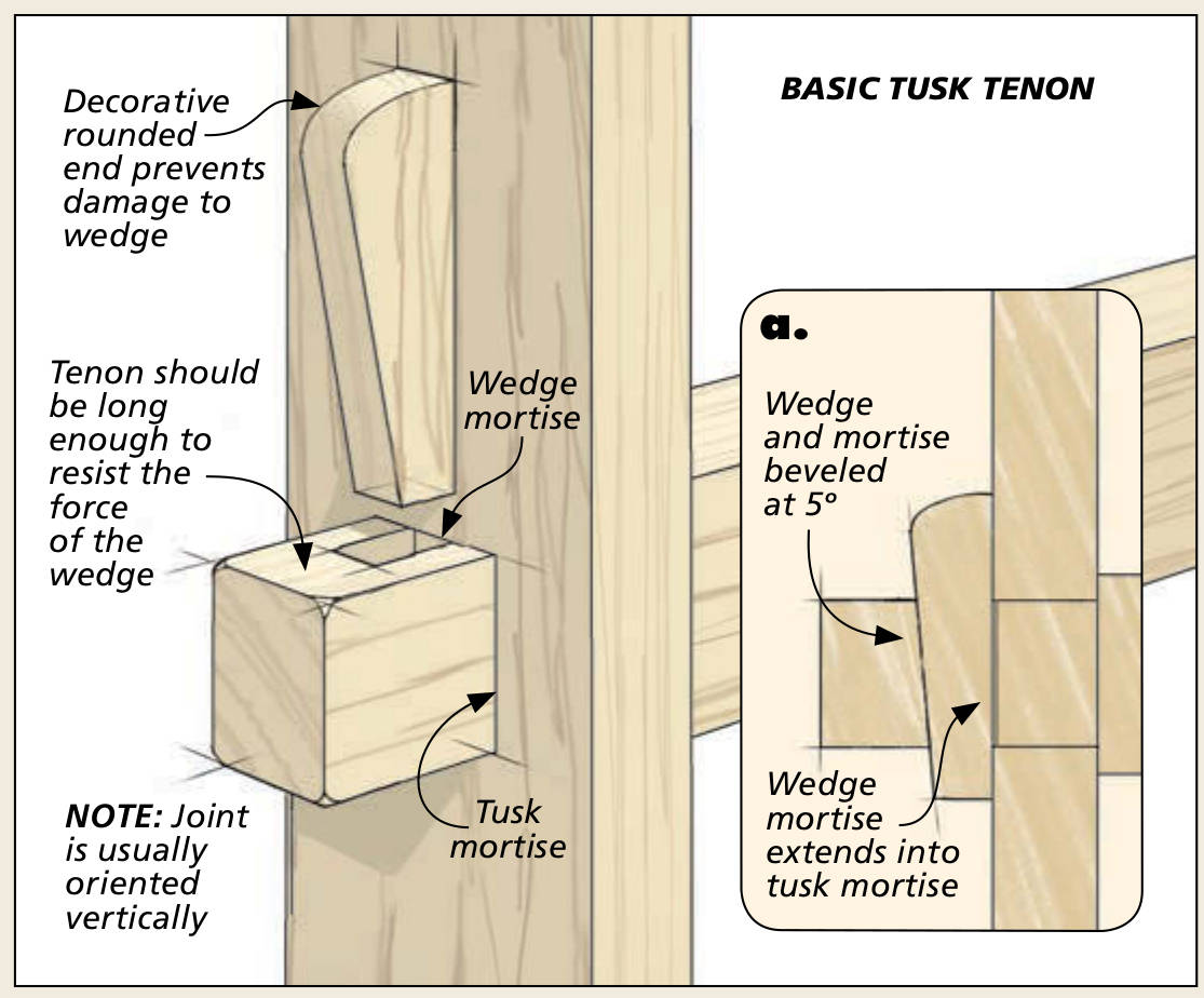
The main structural Joint for the bookcase is a TUSK TENON JOINT, it is a piece or Tenon that goes all the way through a hole or Mortise cut into another piece of wood, then is locked with a loose Wedge or Tusk that is knocked in. I decided to do the Tusk without an angle just working with the pressure of the parts.
-Drawing in Fusion 360
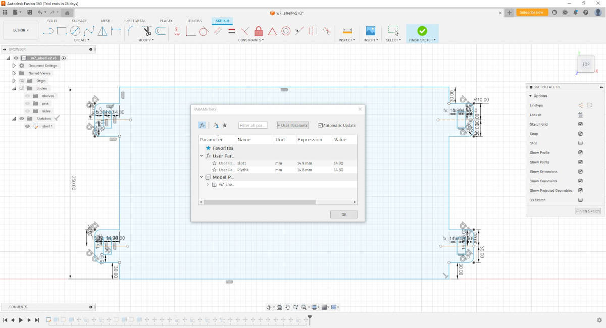
I started to do the shelf plan and made the Tenons and Mortise Parametric in case I needed to change their size after milling to make them bigger or smaller for a better fit.
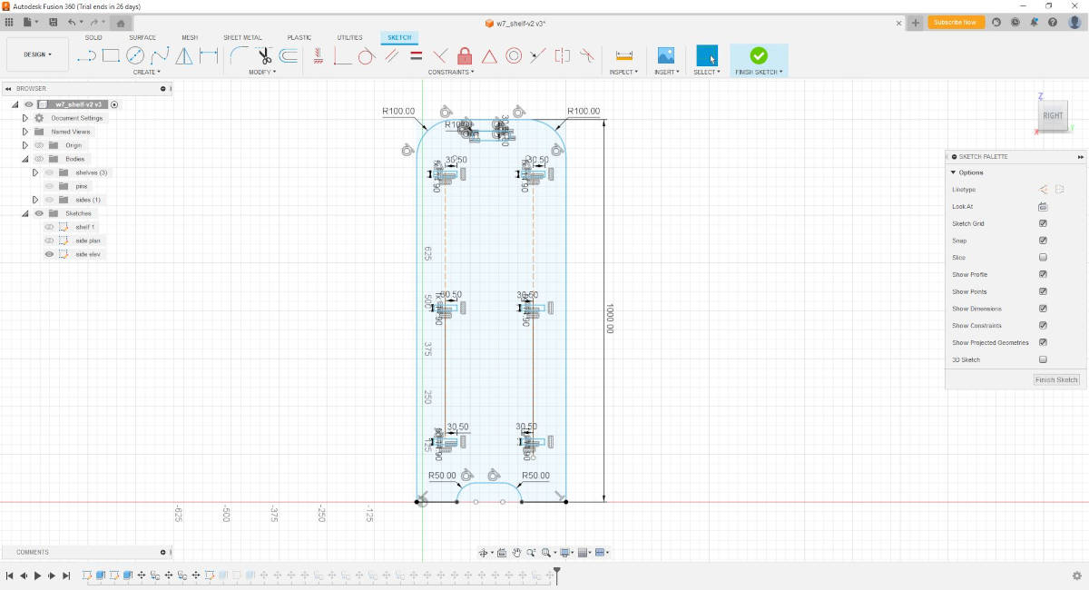
Then I created another sketch in the Y plane to draw the side of the shelf, I constrained the size of the Mortise or holes.
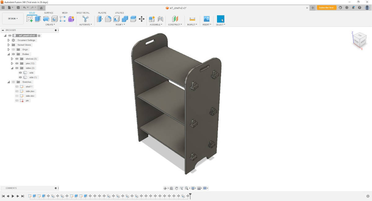
Then I did the bodies for each of the sketches and copy the bodies to generate the 3D model.
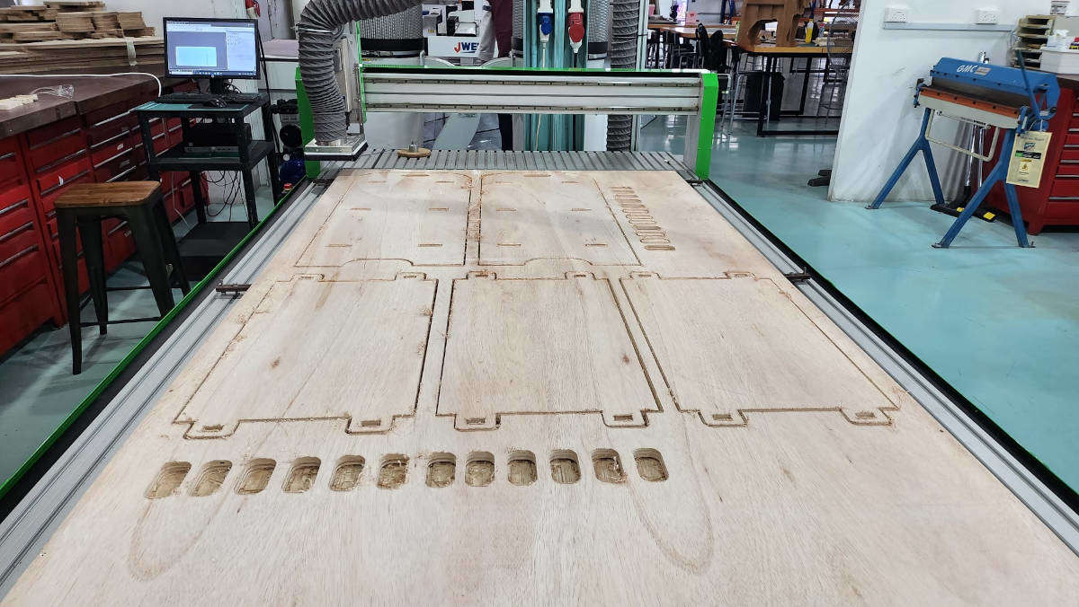
-Milling the Bookshelf
Once the design was ready, I proceed to generate the DXF files from each of the sketches (Right Click on each of the Sketches and save as DXF).
- Shelf
- side
- Wedge
To save time, as we have the program license installed on the CNC computer, this license is not free so we could not use it on our computers.
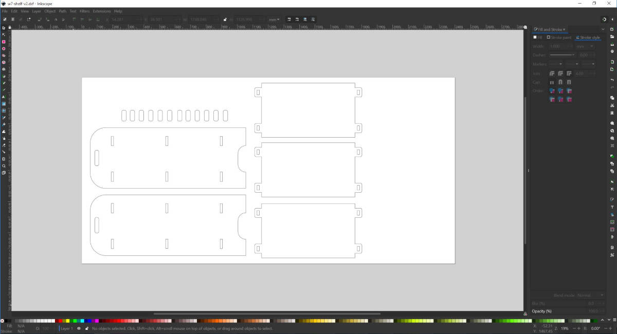
I mounted the parts on Inkscape, on a layout of the approx size of the actual Plywood sheet size 2400mm W x 1200mm H. I copied the parts as they were standard.
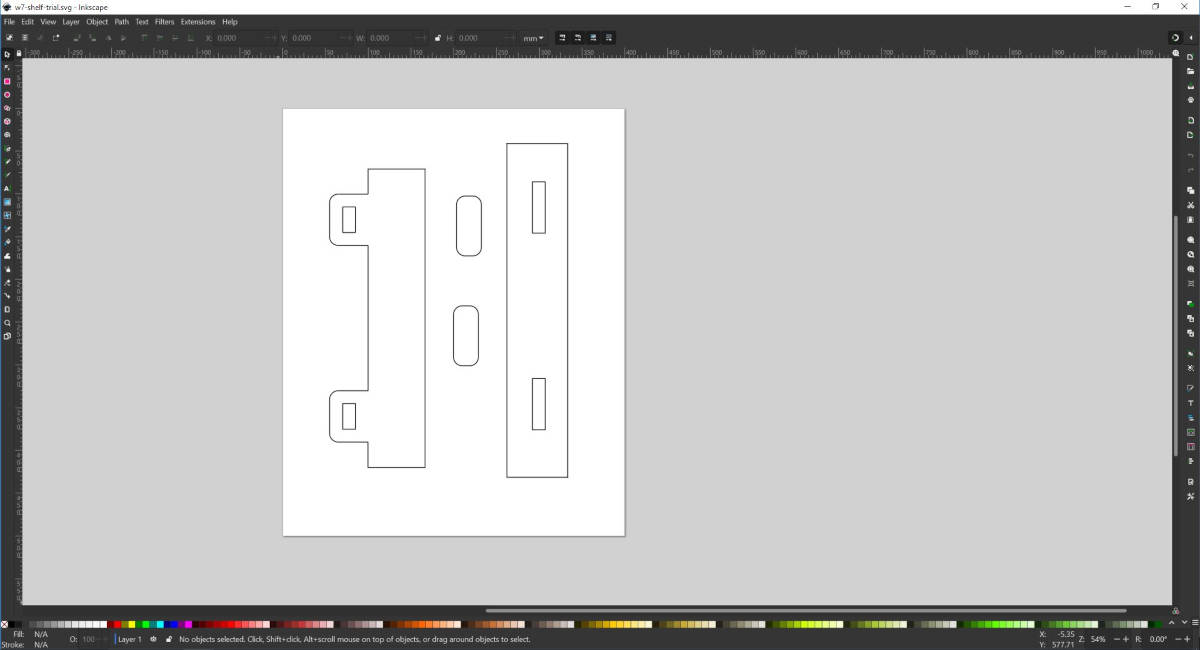
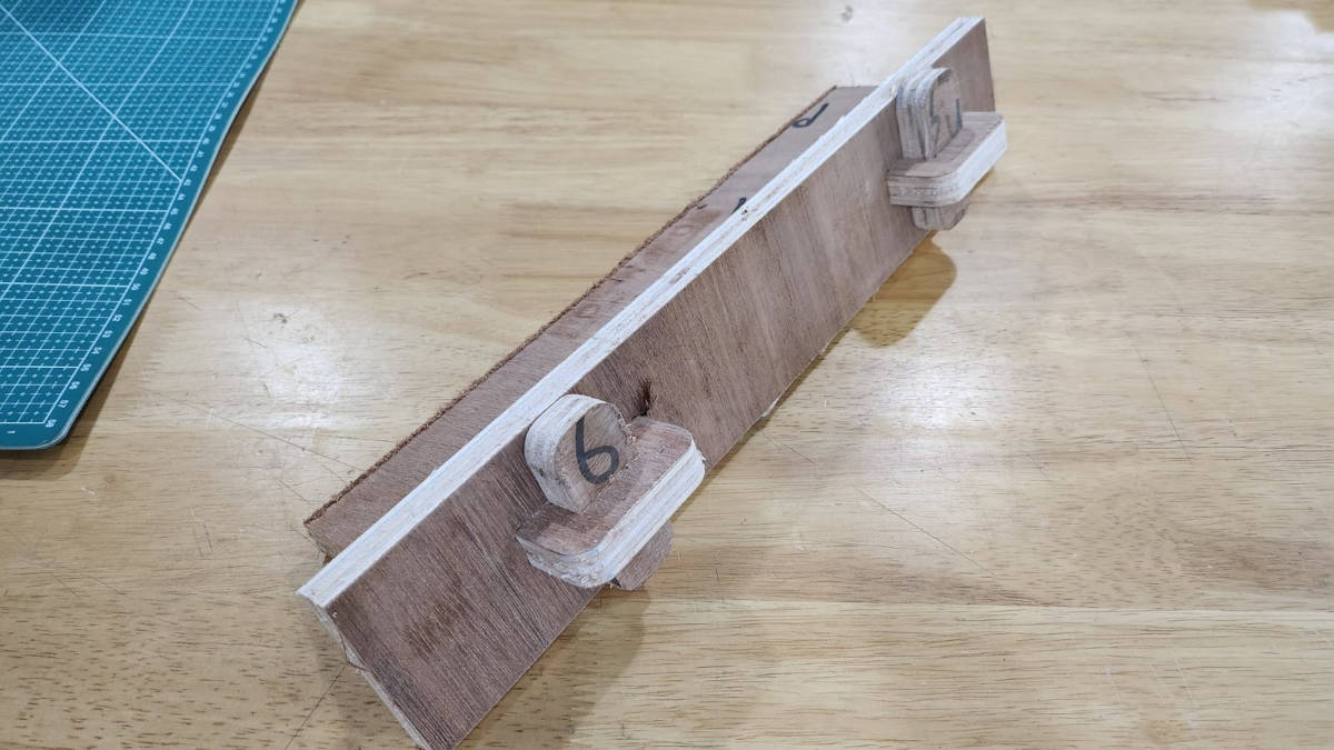
But I prepared a file to do a sample of the joints first to see if the sizes were the fit I was looking for. I wanted the tusks to get into the mortise with pressure to be done by hand and the Loose Wedges to be gently knocked in with a rubber mallet.
-VCarve-Pro
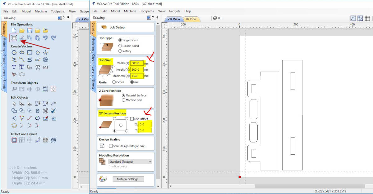
Once these files were ready I proceed to the CNC machine computer to download and open them in VCARVE-PRO. There is a free download of the program option, but we can not save the files…it is just for practice.
When the file is opened in Vcarve-Pro we start to set the size of the material, in this case as it is a small sample I set 500 W x 500 H x 15mm D (this is the thickness of plywood I have chosen for the project).
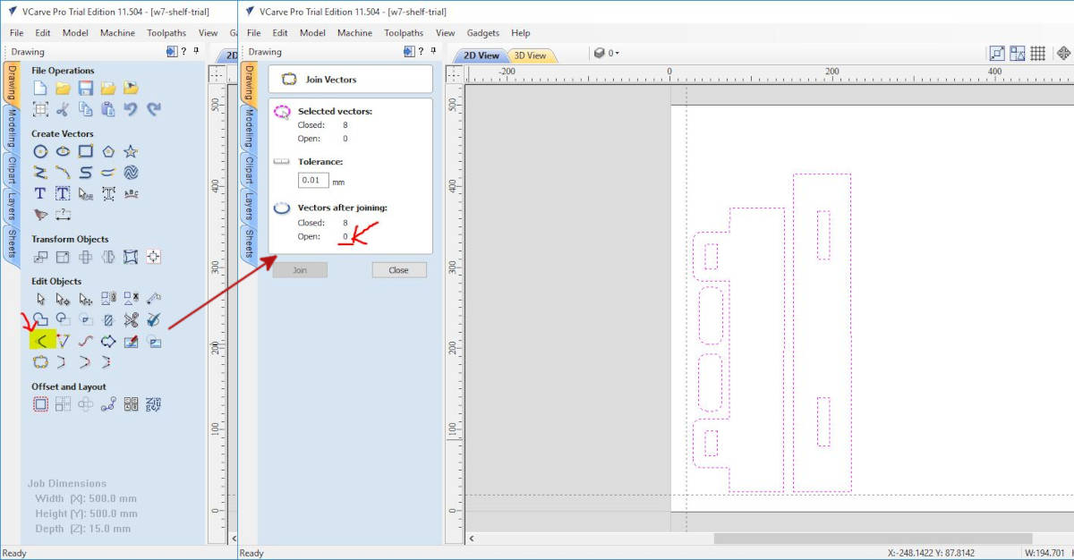
I followed by closing the lines, if they are not closed we can not generate the milling path. To do so we select all the polylines and click on the Joint tab, if there are open corners the program tells us and we accept to close them.
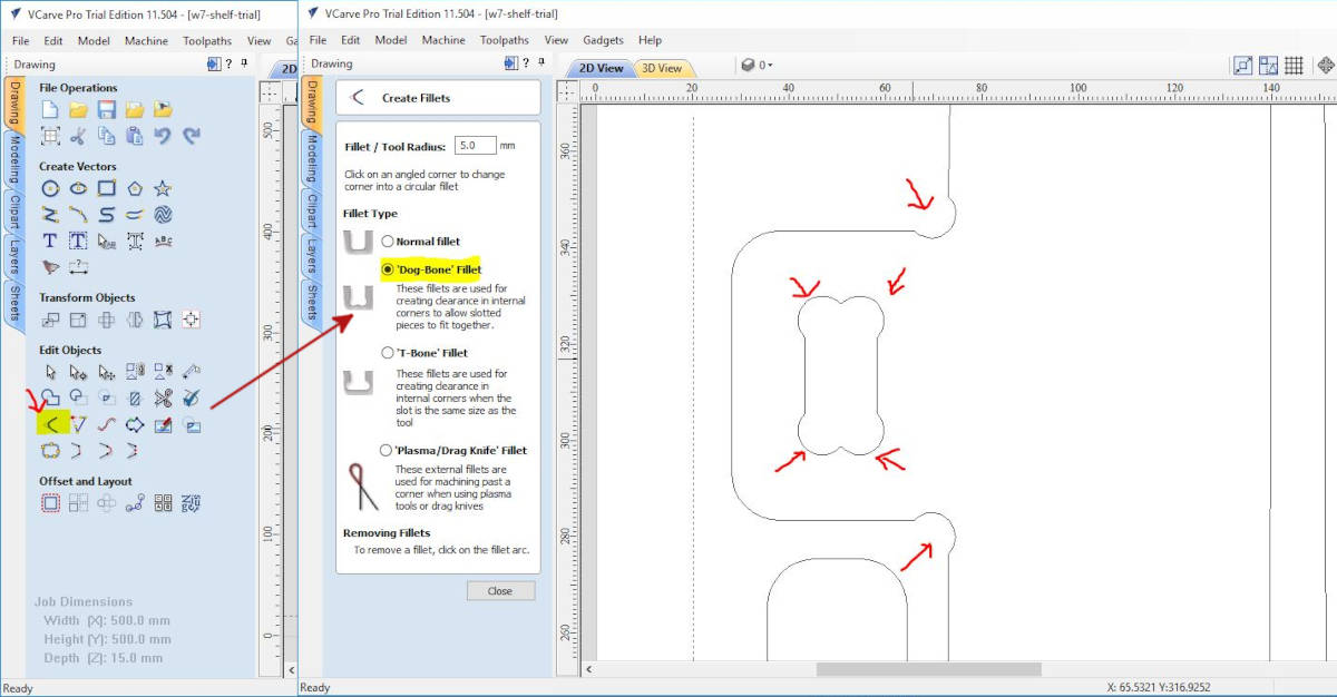
The pieces when are milled and we need to do joint fittings it is better to have the corners rounded inside, to do so we click in the tab Create fillets > Dog-Bone Fillet, and we select all the corners we want to do the Dog-Bone fillet.
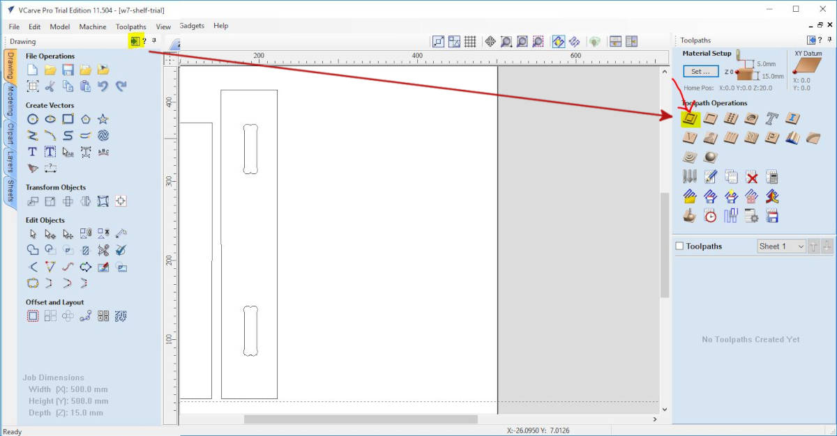
At this point the 2D settings are ready, so we move to Toolpath Commands, in this window we set the machine's way of doing the mill and the characteristics. We select the 2D Profile Toolpath, which is for cutting through the material settings.
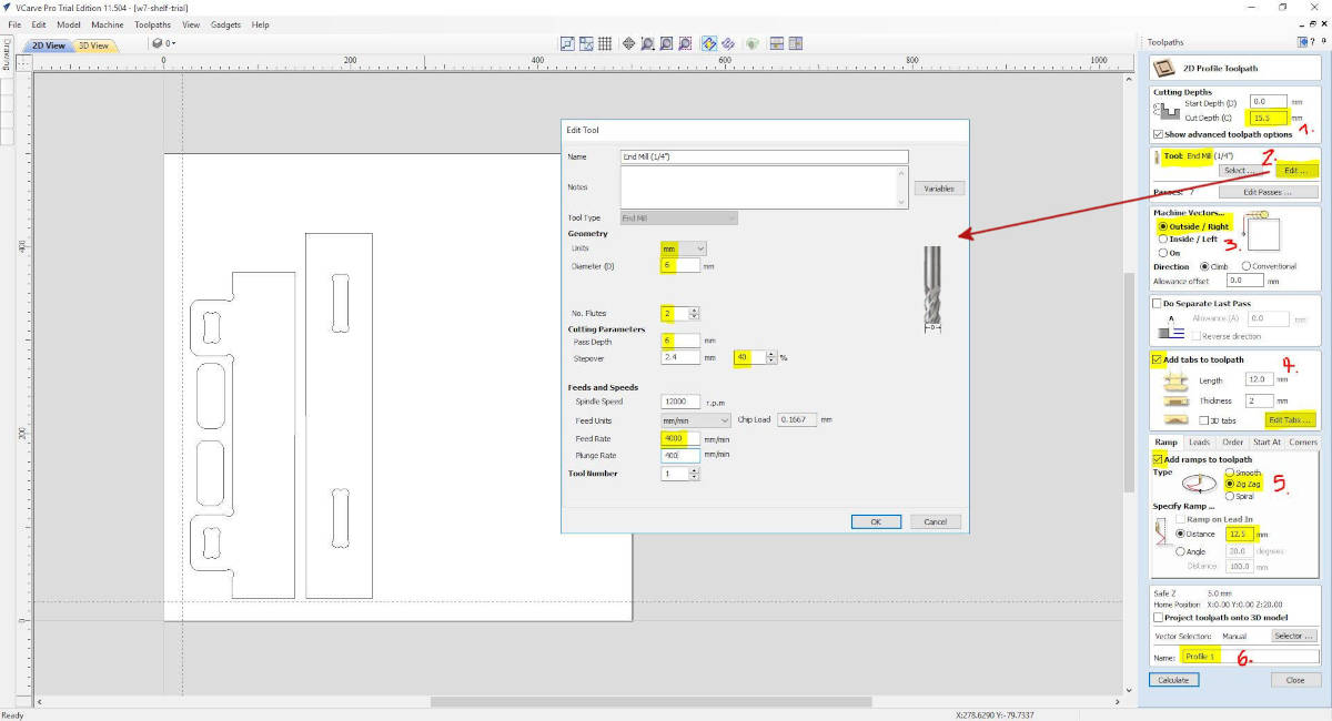
At the 2D Profile Toolpath window, we have to select several options:
- Depth of the board, in my case 15mm we add 5mm in case the material is bended
- Tool: End mill we choose Edit
- Machine Vectors, we select Outside so we don't lose material at the borders while milling.
- Add tabs to toolpath, we select Edit tabs
- Add ramps, we select it and choose zig zag with a distance of 12.5mm
- We name the profile to save later and Click on Calculate.
For the Tool End mill, we choose the following settings:
- Units mm
- The diameter of the End mill is 6mm
- No of flutes is 2
- The pass depth of the radius of the mill is 6mm
- Stepover of 40%
- I just changed the Feed Rate to 4000
- With these feeds and speed, we have a chip load of 0.1667 within the recommended range of 0.025-0.25mm
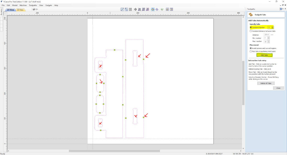
The addition of the Tabs at the toolpath is very important, as the milling is in the process the pieces can get loose and can be shoot by accident to someone's face or body causing accidents. In our lab, the minimum of tabs per piece is 4.
The exception is the holes that are small and won't generate leftover pieces. The program has the option to locate the 4 tabs by default, or we can locate them manually or edit their position in the drawing by clicking on the points.
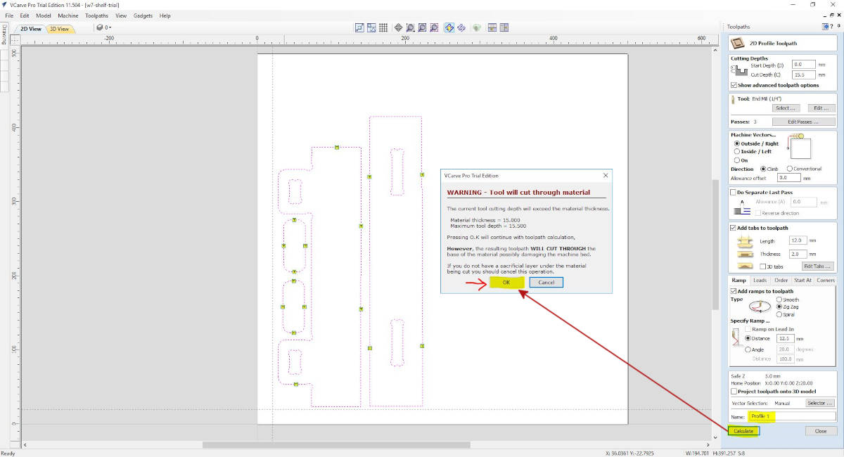
As all the Toolpaths settings are ready we hit calculate, the program will warn us we are cutting through the bed, but the Lab has considered this putting a “Sacrificial Layer” which is a piece of plywood that will protect the bed and will guarantee the mill cut through our material in the case it is bent. So we say OK.
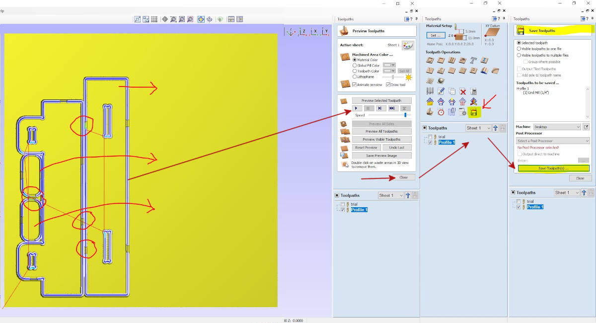
The program sends us to the window Preview Toolpaths, where we can see a simulation at the speed we want.
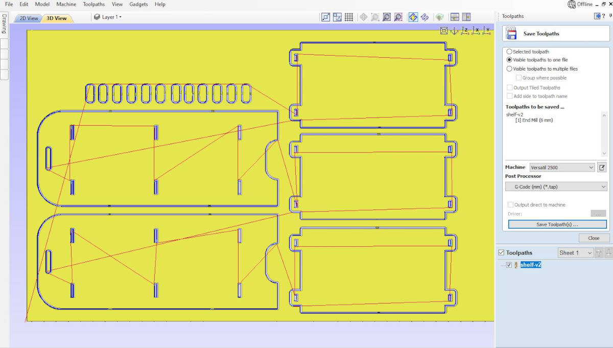
I found with the simulation my pieces were too near to each other and the tabs were getting loose, so I have to go back to the 2D view and move around the pieces and go back to the Toolpath setting once the pieces were more apart, run again the simulator.
When I was ok with the simulation I saved the toolpath into a G-Code file to send to the CNC Program printer.
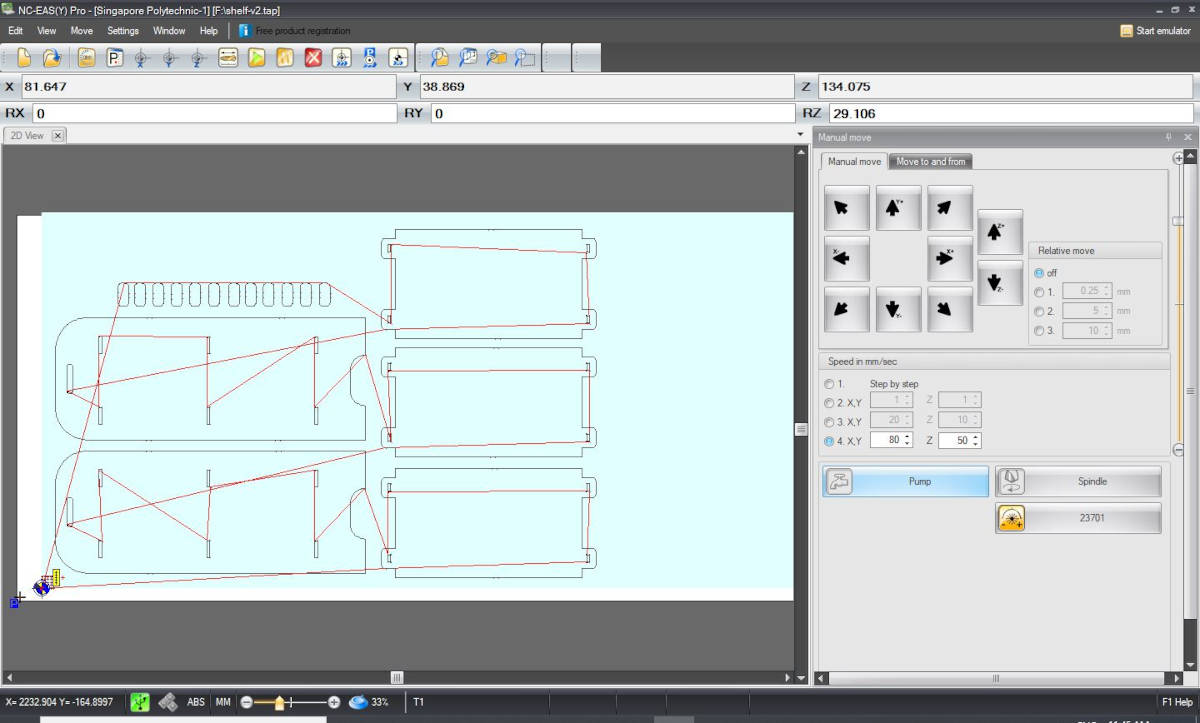
-NC-EAS(Y) Pro
We open the program and the first operation we do is to set the spindle positioning, and the material positioning.
We open the file and once we are ready we start the woodchip vacuum and hit START on the computer. We have to make sure to have the handset with us to press the emergency in case we have to stop the milling.
The joint samples were ready and I did a little bit of sanding and put them together, I realized that I was missing some dogbones in some corners and fixed this into the file, and was ready to mill the week project.
The only thing I have changed in V-Carve Pro for the project milling was the tabs, I revised the quantity and put some more.
Then in NC-Eas(y) Pro, I set again the Spinner ) 0 points and the material 0 points.
When started the milling the machine went to do the Wedges, and we realized they were sucked by the woodchips vacuum, so we thought the number of tabs was not enough, I put less than 4 as they were very small so I thought it wasn't necessary.
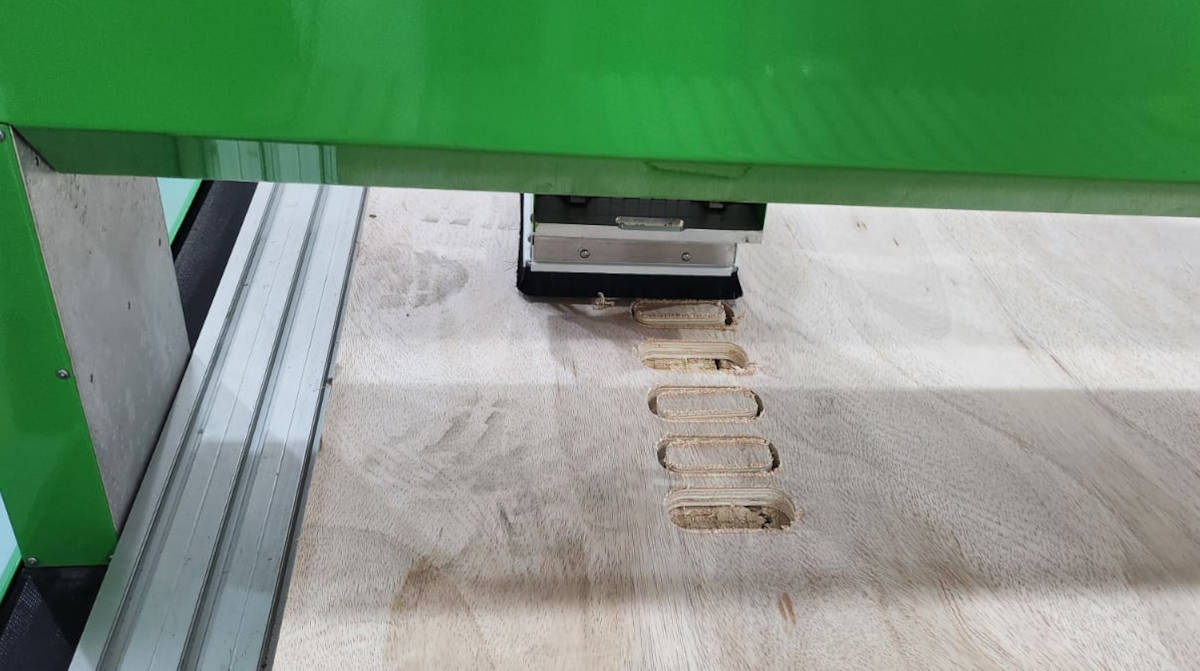
I have to wait until the milling was ready to mill another set of wedges in a spare space I had in the plank and put 4 tabs per wedge and milled again….results: worst the vacuum sucked most of them…what was the problem? The plank was too bent that the CNC milled the tabs. With some of the first round and the second round, I had enough wedges so I didn't have to mill again.
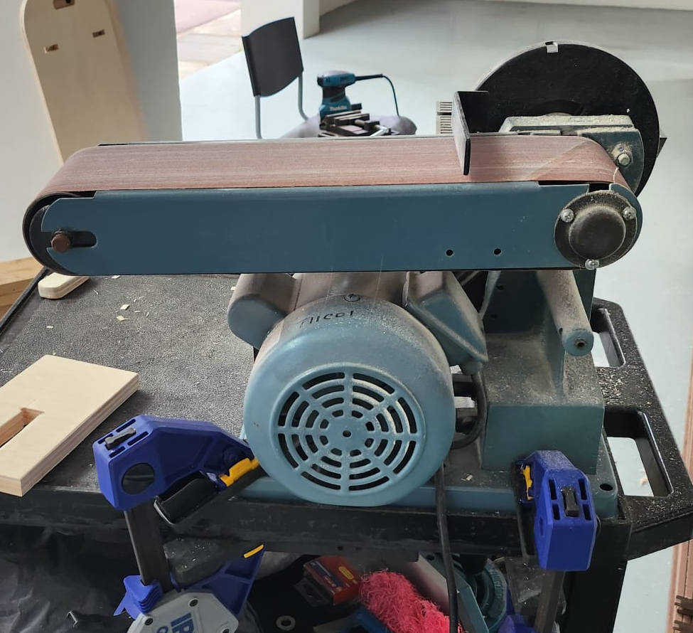
-Sanding and Assembling
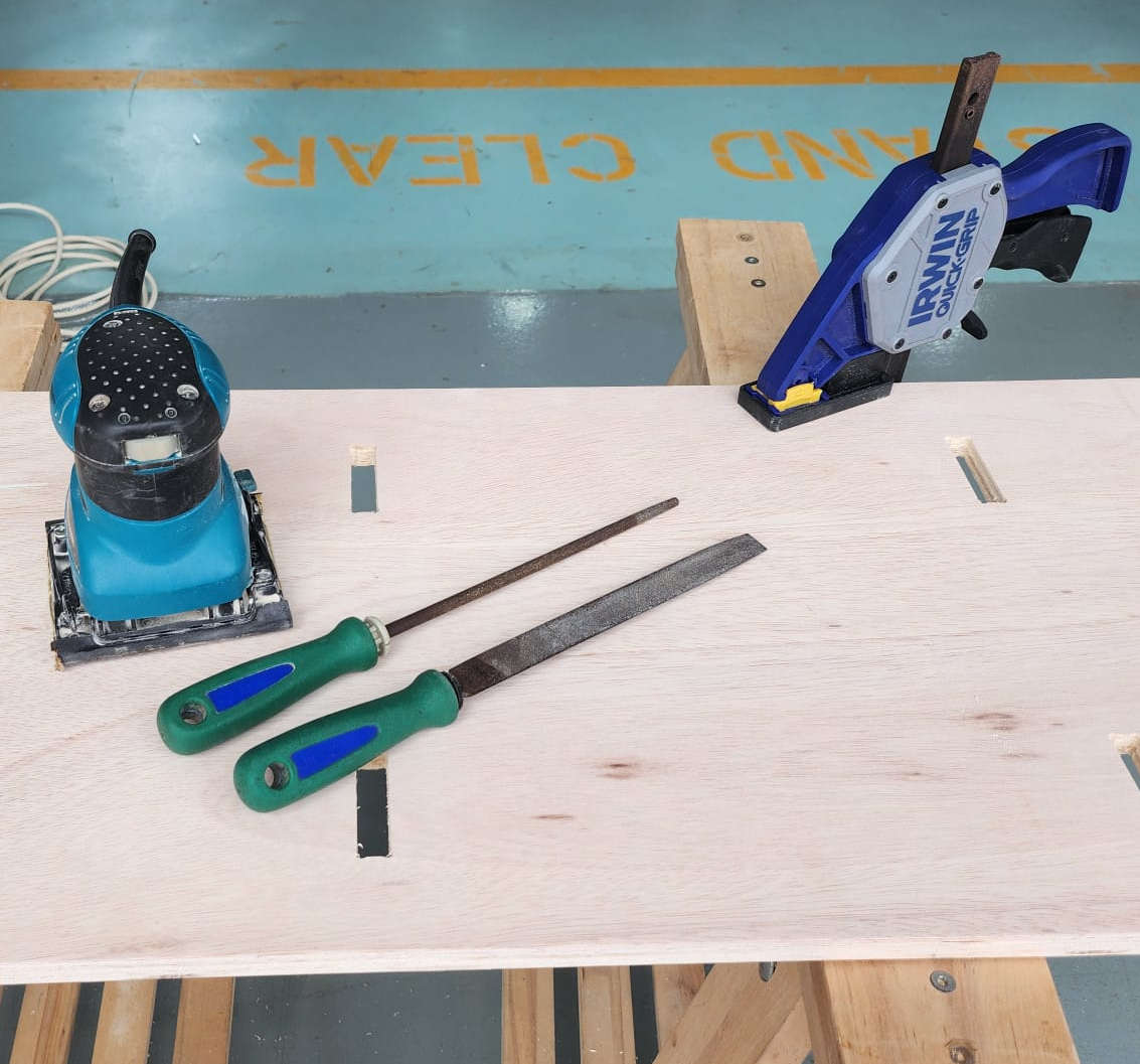
My best friends:
- Orbital sander
- Sand Paper
- Wood rasp Steel round and flat
- Belt and disc sander
- Clampers
|
|
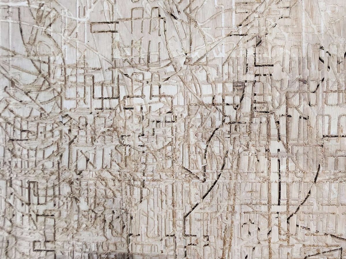
It didn't matter that the sample of the joints was working well, the Mortises or holes were very tight and I had to sand a lot =(
But I had a very nice result
-Takeaways!
I am glad I didn’t do the first design, first and mostly because I didn't like it, second, it was going to be a hell of a production and it was very likely to fail and lastly, it wasn’t parametric at all, while designing I didn’t have time to think about it, I still learning about how to do Parametric design.
It was a good idea to switch to a simpler design, which I liked! And it “worked” although the joints where a bit tight so I have to sand them a lot to fit.
The CNC machine needs a lot of trials and it is quite intimidating, I think for a beginner it is important to stick to a simple project, big shapes not about too much details.
My errors were the joints were a bit too tight, I should’ve left more room when designing it, and something I wasnt accounting on, the tabs were not thick enough (2mm) to hold the pieces, as the plank was warped the CNC cut through them…next time they should be at least 3mm. Lots of the small pieces were swallowed by the vacuum.