Week 9: Group Assignment
- Measure the power consumption of an output device
- Document your work on the group work page and reflect on your individual page what you did
Demonstration
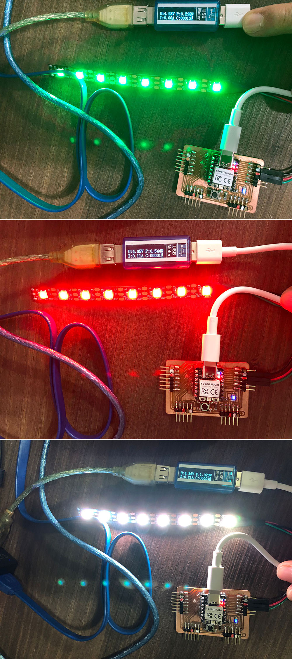
This week we are measuring power. Our instructor Steven demonstrated various output devices for our learning, e.g. LED light strips, OLED, LCD, DC motor, stepper motor and servos. Most of the output devices are self-explanatory.
Measure the power consumption for two servos in action
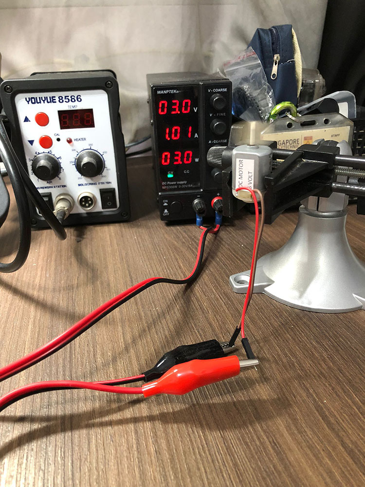
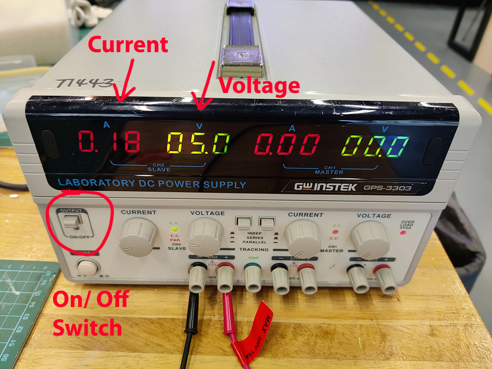
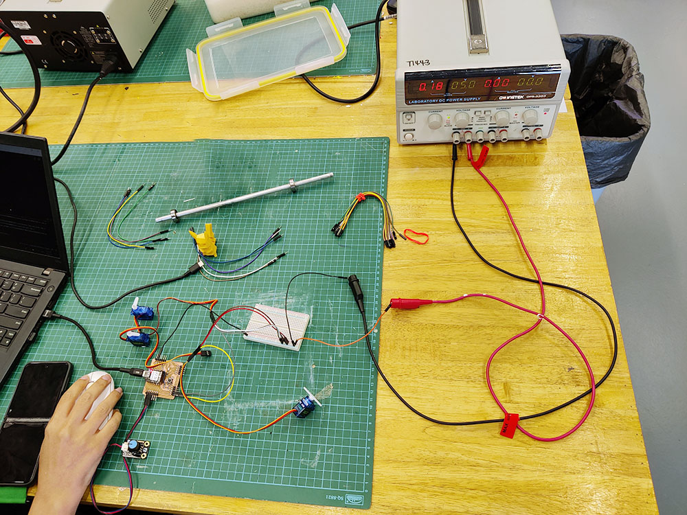
It's time to get hands-on. We setup our two servos with the microcontroller with the power supply in the lab as shown in the photos. Before we switched on the power, the values shown on the Power Supply are the maximum values, E.g. the current will not go above 0.18A (which we later find out is too low).
With the voltage and current shown clearly on the power supply, we could easily get the power consumption ( P = IV ) by multiplying the current and voltage.
Two servo motors controlled by one potentiometer
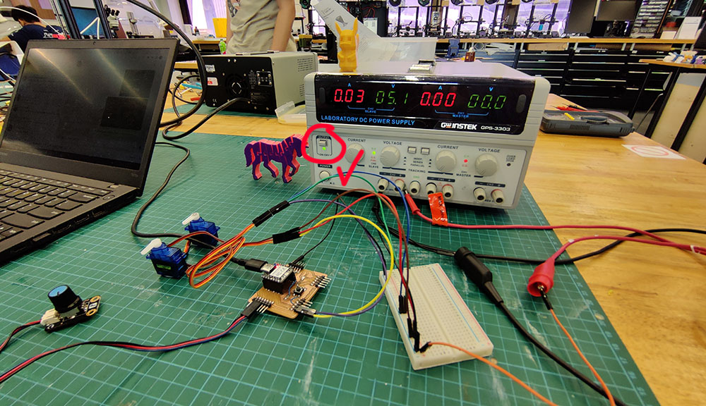
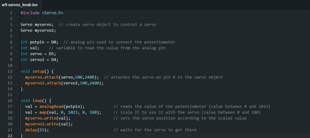
We loaded the Arduino servo library code with the potentiometer to read the current drawn from the servos. We observed that whenever there is a change of direction or speed, the current draw surged (Watch the following video).
The original code was for only one servo motor, we included a second one, and we gave it the same values as the first so they could be controlled at the same time by the potentiometer and move at the same angles.
At the video we can see how the amperes change with the speed we move the potentiometer
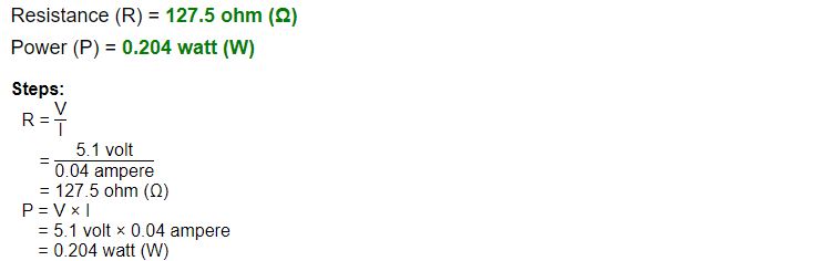
With the values we had for the avergare low of 0.04 amperes with a constant voltage of 5.1 we have:
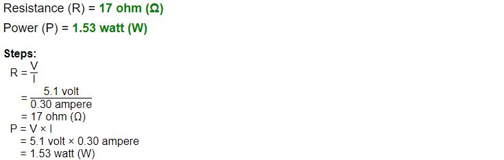
With the values we had for the avergare high of 0.3 amperes with a constant voltage of 5.1 we have:
The Low and High consuption where very related with the speed that we moved the potentiometer the faster the higher power consuption the slower the lower power consuption.
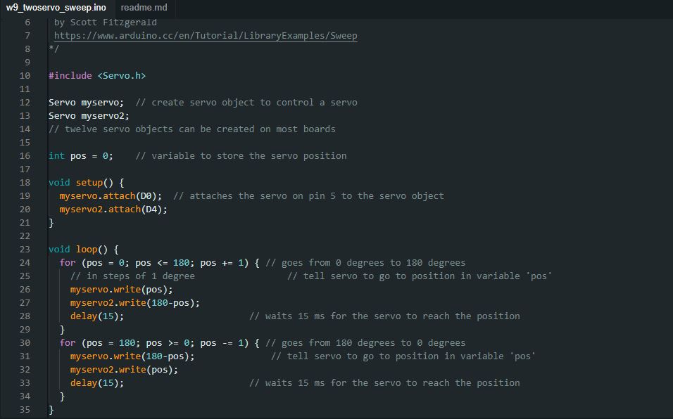
Two servo motros in sweep motion
We modified the code so that the servos move at different directions. We try to change to different speed for each servo but we needed more time to figure it out. We observed similar current surged when there is change of direction and speed.
With this code, the movement of the shaft was more controlled with a lower average of 0.07 amperes, and a higher amperage 0.33. The higher amperage was the result of the servo motor arm movement, when it went pretty fast from the angle of 180 to 0 degrees to start the loop again
We had for the avergare high 0.7 amperes with a constant voltage of 5.1 we then:
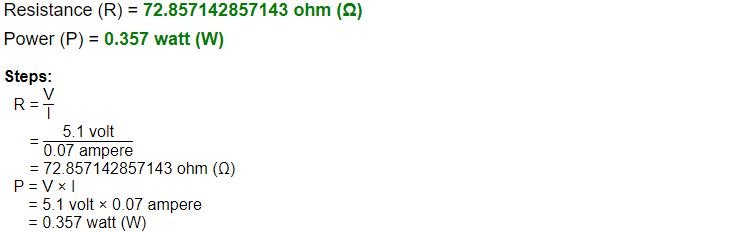
The values for the avergare high of 0.33 amperes with a constant voltage of 5.1 we have:

Measurement Conclusions
The first case where the servo was controlled manually the power consuption was lower, but it was because intentionally we wanted to turn it very slow and then very fast to see the amperes change. The most important conclusion we could make is that the speed of the movement influenced the Powe consuption, the faster the movement the more power consuption the Servo Motors had.