Week 14 Interface and Application Programming
Group assignment
Compare as many tool options as possible
Group site
Individual assignment
Write an application that interfaces a user with an input &/or output device that you made
- For this assignment I used my board with xiao RP2040 and "Processing" to see the data graphically.
- Also tried to make user interface with "Blynk".
Processing
- I tried to use "Processing" to show analog data graphically by referring Adrian's instruction.
- The code for processing is at end of this document. In this code I changed pin number for my board.
-
On week 11, I made a small board for step response designed by Adrian (see this site). Then connected to my board to read analog response.
-
This time I used analog pin for taking analog input. I referred Adrian's processing sketch and modified shape parameters like color or size. And uploaded the sketch.
- Once uploaded the sketch to xiao board, then I run Processing sketch.
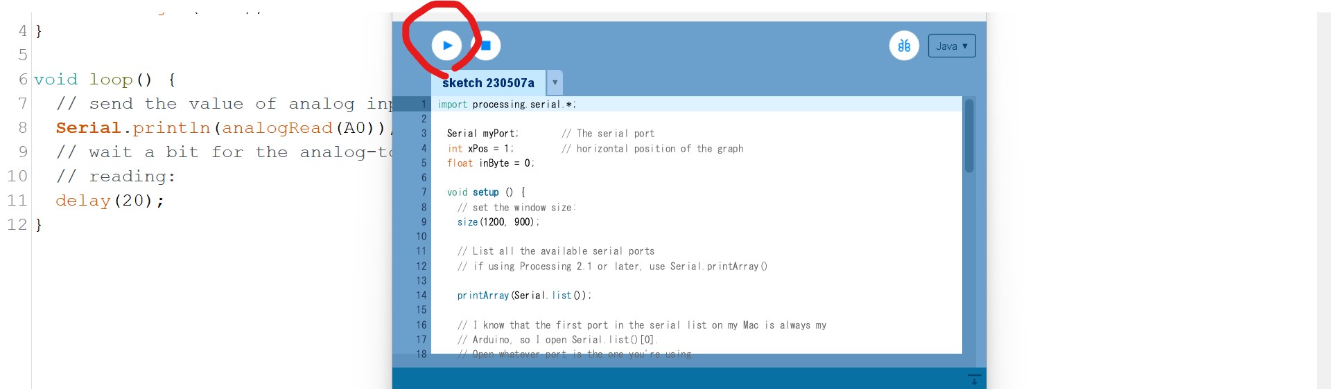
- Processing window shows graphic along the analog input.
- Processing is working on my PC, and the board and PC connection is USB serial. Then Processing taking data from the connection. Same as serial plotter on Arduino IDE.
- The format of the data of this serial communication is a string with the following format: xxxxx\n where xxxx are several digits from the result and \n indicates new line.
- In Processing sketch, I can draw shapes like below;
- First of all, I need to define the size of drawing field using "size(x,y)"
- For color of a line, or outline of a shape I can set using "stroke". like setting color "stroke(255,0,0)//red line".
- For width of a line, use "strokeWeight" like "strokeWeight(4)//set width 4, if no setting with this function default is 1.
- For not showing the outline, use "noStroke()".
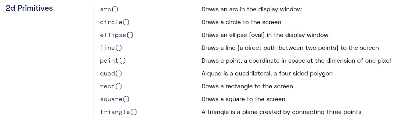
- 2D shapes, "rect()" for rectangular, "ellipse()" for oval or circle...
- I can refer this cheat sheet from Processing site.
User interface by Blynk
- As I am so interested in remote control of devices, our instructor suggested to try Blynk. This week my goal was to control the LED by mobile through internet (not the same wifi connection)
- I referred this YouTube instruction and the code in this site
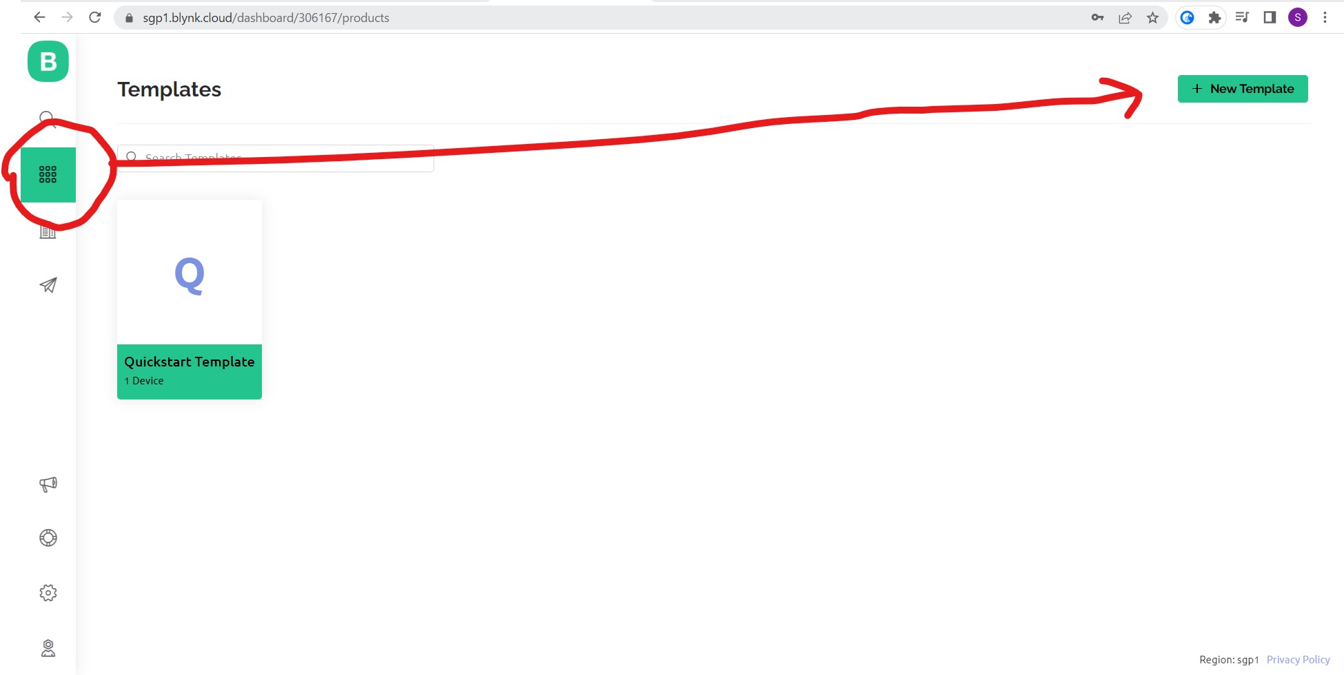
- After created my account on Blynk, I started to create new template.
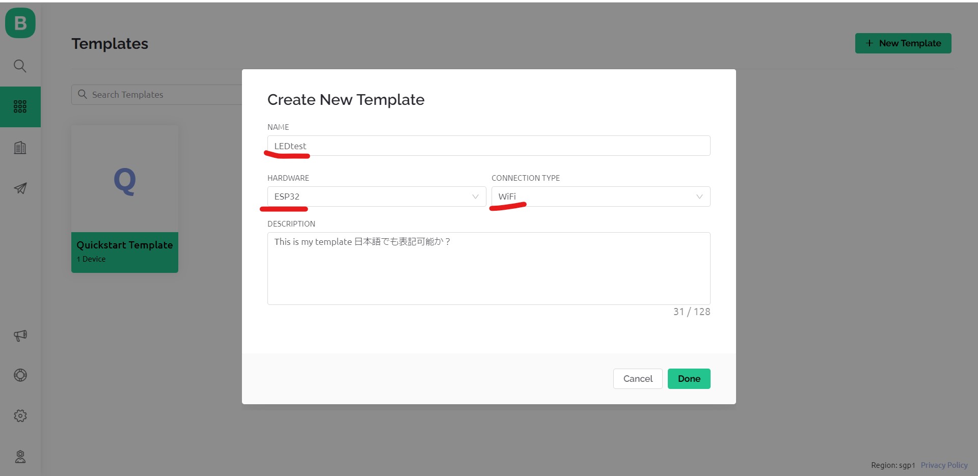
- I named "LEDtest" for this template and chose esp32 for hardware and wifi for connection type.
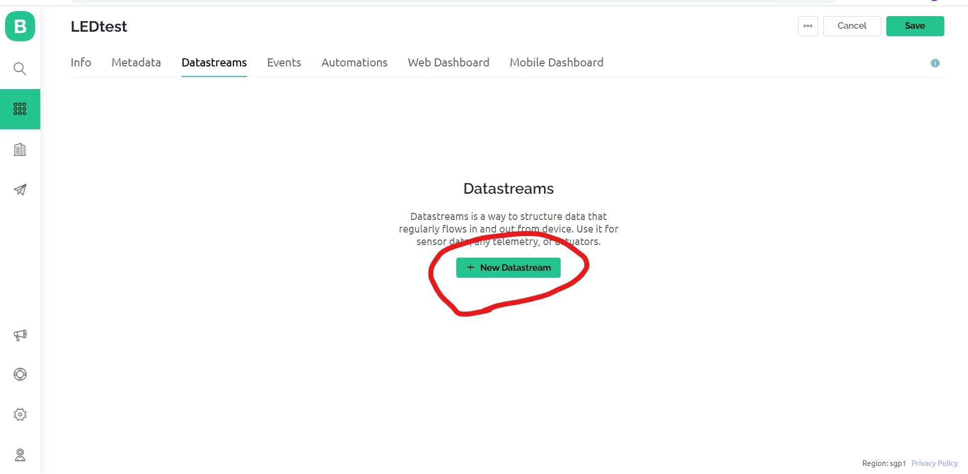
- Next I need to set "datastream", then click "Datastream" tab

- Click "+ New Datastream"
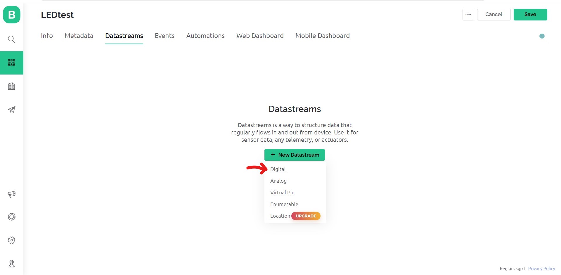
- Chose "digital" in the pull down list
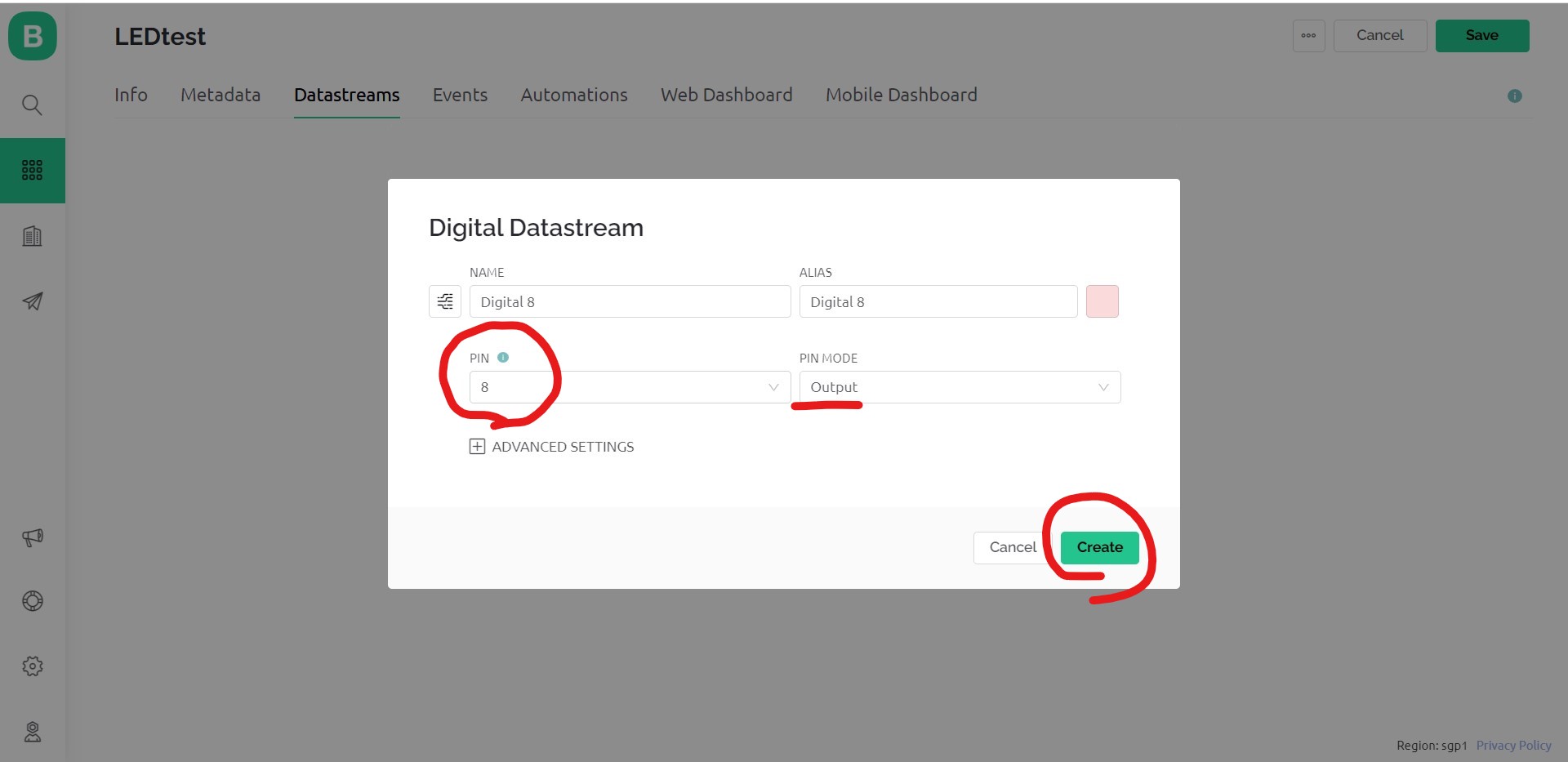
- Set pin number for the target LED, this case 8 for my board,pin mode is "Output" to blink it.
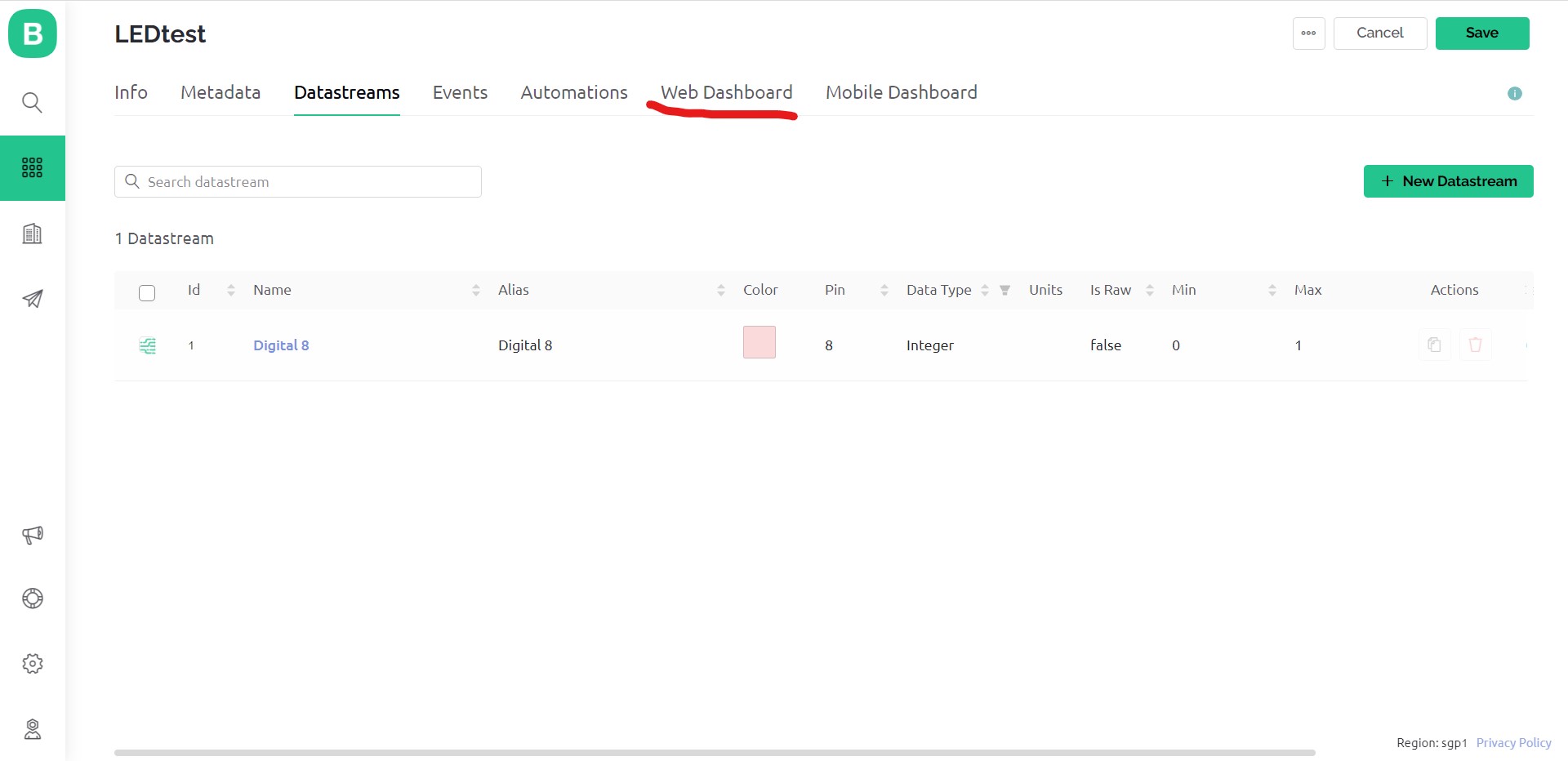
- Now the datastream is done. Next set "Web Dashboard"
- I can drag and drop the functional parts to set up user interface.
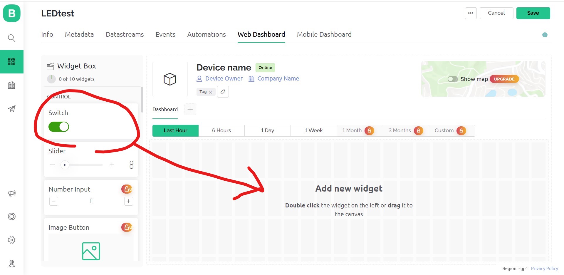
- I picked up 2 interface parts. "Switch" and "LED"
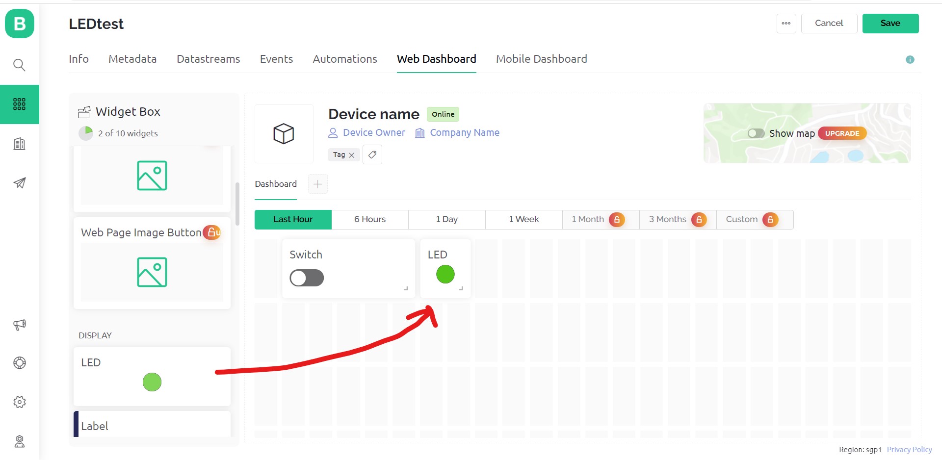
- Now I need to set up each interface part's settings.
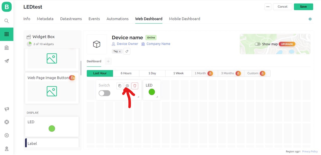
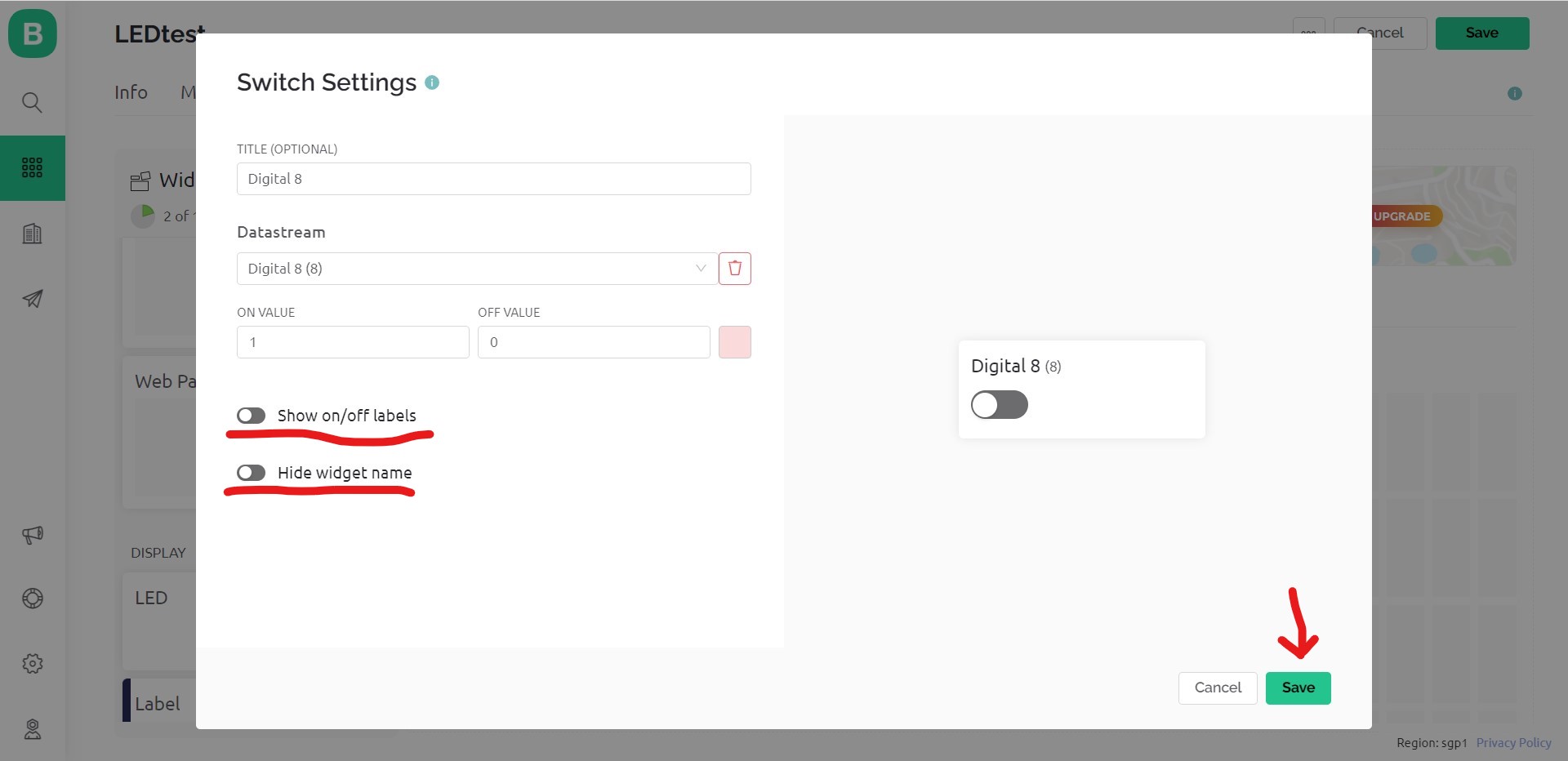
- For the "Switch" setting, I choose datastream from the pull down list.
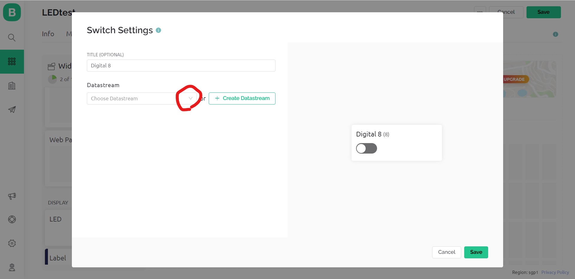
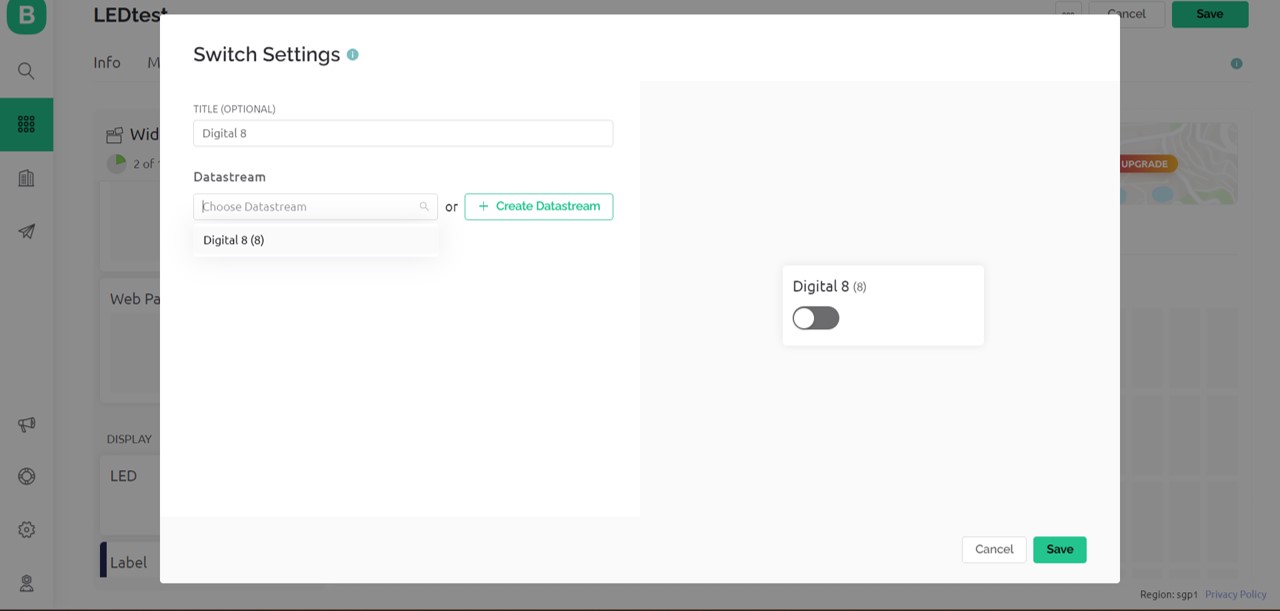
- I can modify appearance if needed.
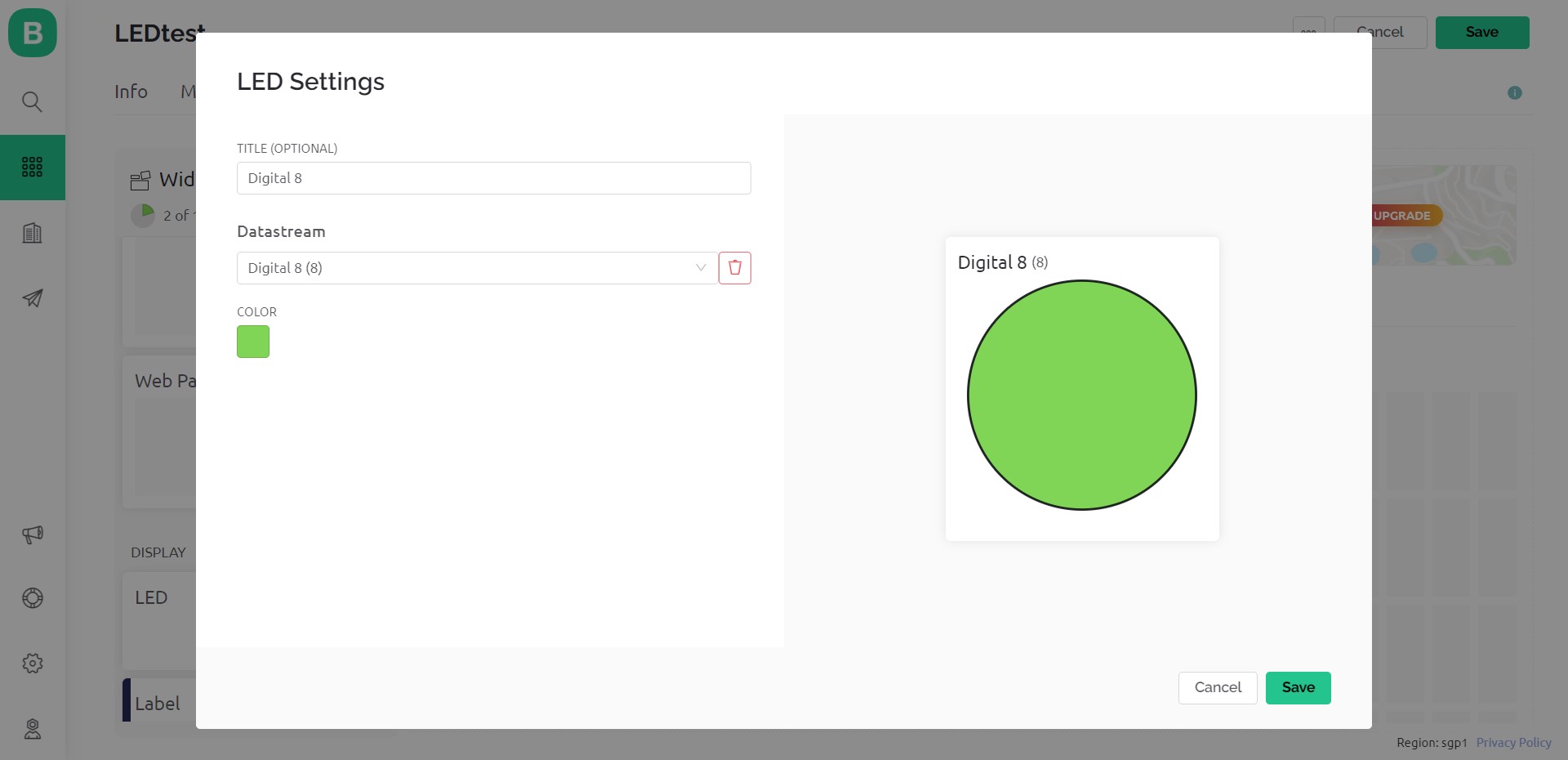
- In the same way, setting of "LED"
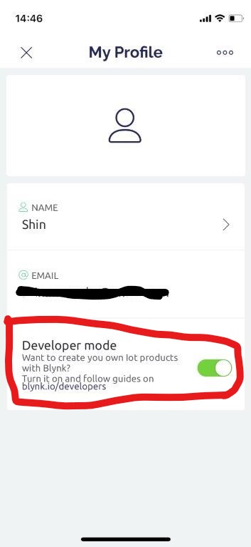
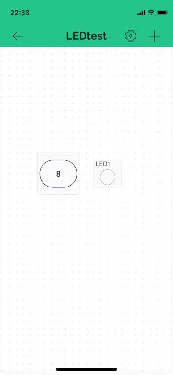
- Next "Mobile Dashboard" setting on my mobile, download app in my mobile and log in
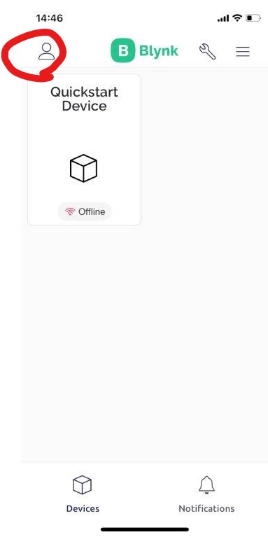
- Confirm "developer mode" is working
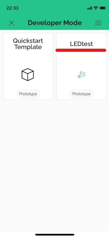
- Pick target template in "Developer mode"
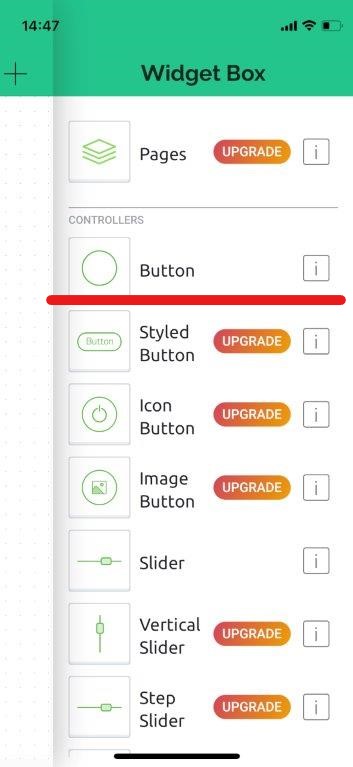
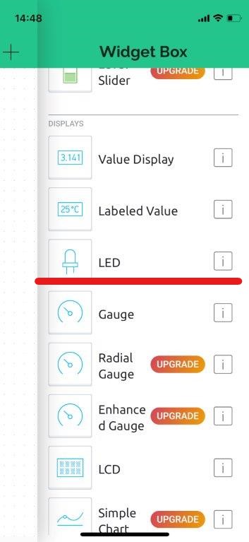
- Pick up necessary interface parts (I picked up the same as PC interface).
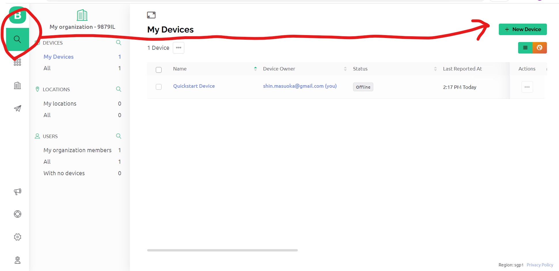
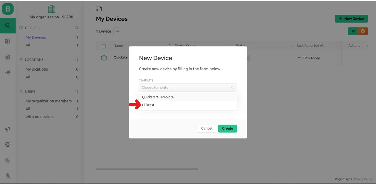
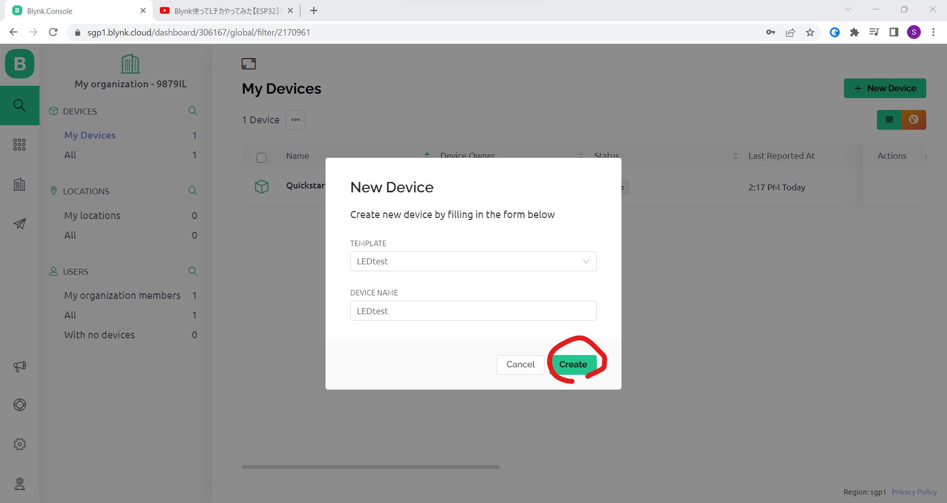
- Now the "template" setting is done. Next come back to my PC and click "+ New Device"
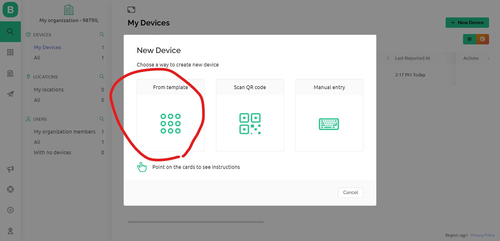
- I have already set up an template, so choose "From template" and bring what I set up.
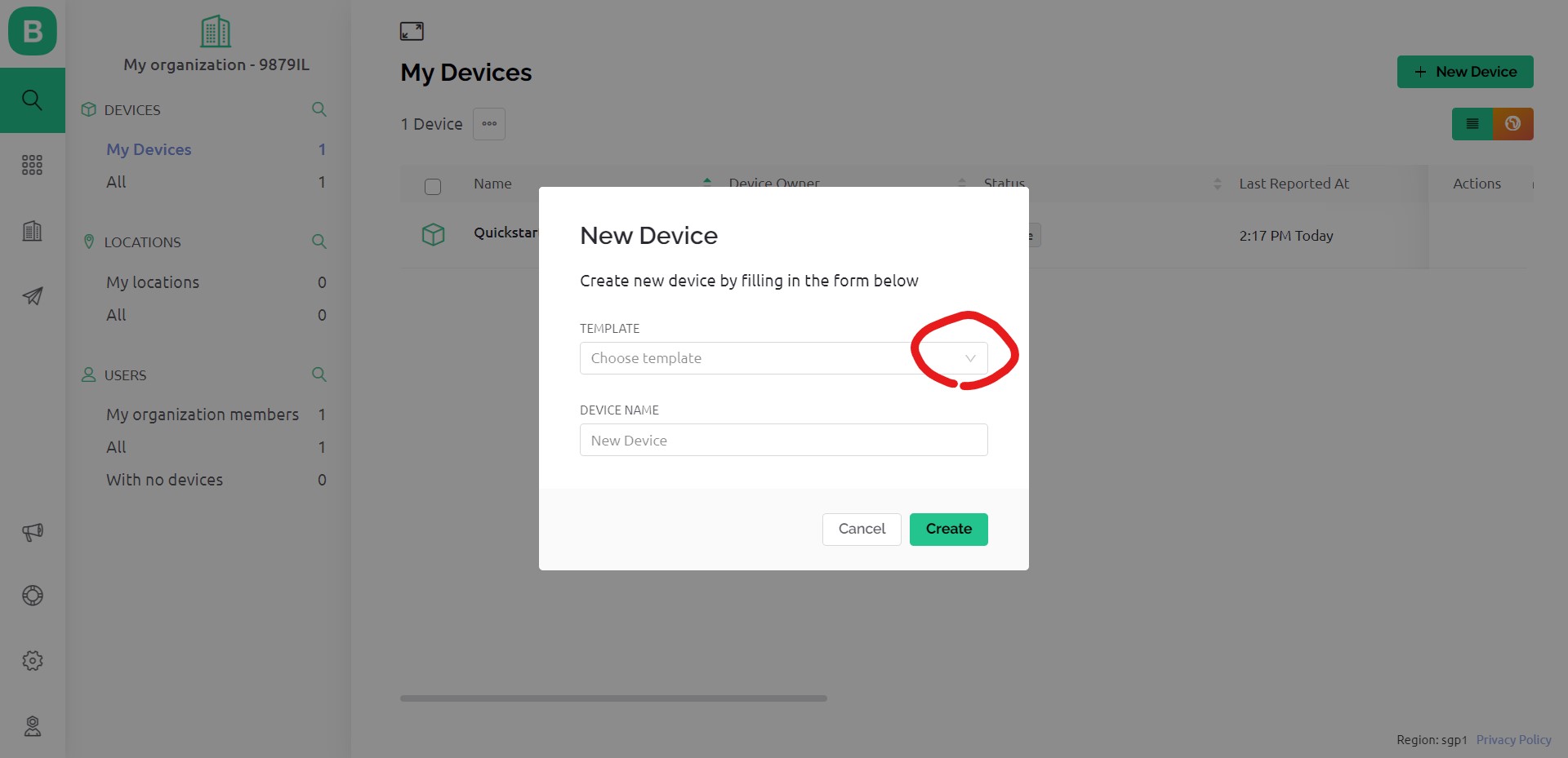
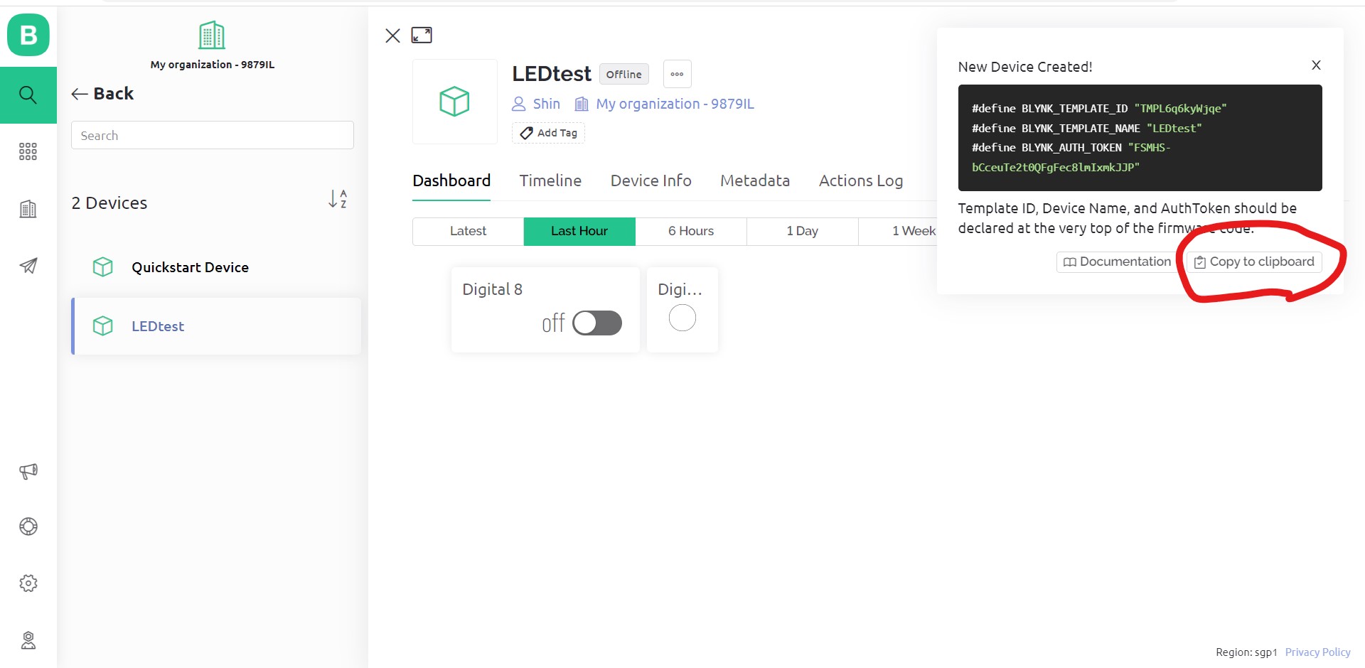
- Then what I create is shown as "Device", also Token is issued. Now I copy and paste in the code for the Blynk device.
- I uploaded the code to my board with Arduino IDE. And controlled the LED via mobile or PC interface. Especially mobile was not on the same wifi.
Thoughts and feelings
- As a beginner of programming, this week was overwhelming. As Neil told I could not master a language in a week. What I did was just find sample code and bit modified. I managed to show graphic along analog input, but could not adjust.
- Using Blynk and set up user interface was very fun. I would like to use this more.
Data, Codes
Code for my xiao board
//tx_rx03  Robert Hart Mar 2019.
//https://roberthart56.github.io/SCFAB/SC_lab/Sensors/tx_rx_sensors/index.html

//Modified by Adrián Torres Omaña
//Fab Academy 2023 - Fab Lab León
//Step Response TX, RX
//Fab-Xiao

//Pin number modified by Shin Masuoka

//  Program to use transmit-receive across space between two conductors.
//  One conductor attached to digital pin, another to analog pin.
//
//  This program has a function "tx_rx() which returns the value in a long integer.
//
//  Optionally, two resistors (1 MOhm or greater) can be placed between 5V and GND, with
//  the signal connected between them so that the steady-state voltage is 2.5 Volts.
//
//  Signal varies with electric field coupling between conductors, and can
//  be used to measure many things related to position, overlap, and intervening material
//  between the two conductors.
//

long result;   //variable for the result of the tx_rx measurement.
int analog_pin = 26; //  GPIO 26 of the XIA0 RP2040
int tx_pin = 0;  //     GPIO 0 of the XIAO RP2040
void setup() {
pinMode(tx_pin,OUTPUT);      //Pin 2 provides the voltage step
Serial.begin(115200);
}

long tx_rx(){         //Function to execute rx_tx algorithm and return a value
                      //that depends on coupling of two electrodes.
                      //Value returned is a long integer.
  int read_high;
  int read_low;
  int diff;
  long int sum;
  int N_samples = 100;    //Number of samples to take.  Larger number slows it down, but reduces scatter.

  sum = 0;

  for (int i = 0; i < N_samples; i++){
   digitalWrite(tx_pin,HIGH);              //Step the voltage high on conductor 1.
   read_high = analogRead(analog_pin);        //Measure response of conductor 2.
   delayMicroseconds(100);            //Delay to reach steady state.
   digitalWrite(tx_pin,LOW);               //Step the voltage to zero on conductor 1.
   read_low = analogRead(analog_pin);         //Measure response of conductor 2.
   diff = read_high - read_low;       //desired answer is the difference between high and low.
 sum += diff;                       //Sums up N_samples of these measurements.
 }
  return sum;
}                         //End of tx_rx function.

void loop() {

result = tx_rx();
result = map(result, 17000, 23000, 0, 1024);  //I recommend mapping the values of the two copper plates, it will depend on their size
Serial.println(result);
delay(100);
}
Code for Processing
//Based on Adrian's sketch
//Step Response
//Shin Masuoka modified shape parameters
//XIAO RP2040

import processing.serial.*;

float sensorValue; //variable for the serial data
Serial myPort;

void setup() {  //as dynamic/setup function called initially, only once
  size(1500, 800);// is the window (1024=sensor max. value)
  //replace the port String with the port where your Arduino is connected
  //myPort = new Serial(this, "/dev/tty.wchusbserial1450", 115200);
  myPort = new Serial(this, "COM8", 115200); // serial port
  background(255);  //set background white

}

void draw() {  //draw function loops

  stroke(255,0,0); // color of outline
  strokeWeight(100);
  fill(0,255,0,20); // color inside
  rect(0, 0, sensorValue, height); //position and size

  fill(255,70);
  rect(sensorValue, 0, width-sensorValue, height);

  println(sensorValue);
  fill(0,0,255);// these are the colors inside
  text(sensorValue + " " , sensorValue, height/2);
  textSize(200);

}

void serialEvent(Serial myPort) { // sketch read the serial data
  String inString = myPort.readStringUntil('\n');
  if (inString != null) {
    inString = trim(inString);
    float[] values = float(split(inString, ","));
    if (values.length >=1) {
      sensorValue = values[0]; //first value in the list
    }
  }
}
Code for Blynk device
// Template ID, Device Name and Auth Token are provided by the Blynk.Cloud
// See the Device Info tab, or Template settings

#define BLYNK_TEMPLATE_ID "TMPL6q6kyWjqe"
#define BLYNK_TEMPLATE_NAME "LEDtest"
#define BLYNK_AUTH_TOKEN "FSMHS-bCceuTe2t0QFgFec8lmIxmkJJP"

// Comment this out to disable prints and save space
#define BLYNK_PRINT Serial

#include <WiFi.h>
#include <WiFiClient.h>
#include <BlynkSimpleEsp32.h>
#include <math.h>

char auth[] = BLYNK_AUTH_TOKEN;

// Your WiFi credentials.
// Set password to "" for open networks.
char ssid[] = "xxx";
char pass[] = "xxx";

BlynkTimer timer;

// the number of the LED pin
const int ledPin = 8;

// This function is called every time the Virtual Pin 1 state changes
BLYNK_WRITE(V8) ///LightPin:Relay_operates_on_LOW_Input_Voltage_coneccted_NC
{
  int buttonState = param.asInt();
  // Update state
  if(buttonState == HIGH){
     digitalWrite(ledPin, HIGH);
     Serial.println("HIGH");
  }else{
     digitalWrite(ledPin, LOW);
     Serial.println("LOW");
  }
}

// This function is called every time the device is connected to the Blynk.Cloud
BLYNK_CONNECTED()
{
  Serial.println("Connected!");
}
//////////////////////////////////////////////////////////////////////

void setup() {
  // Serial port for debugging purposes
  Serial.begin(115200);

  //pinMode setting
  pinMode(ledPin , OUTPUT);

  //WiFI Setting
  Blynk.begin(auth, ssid, pass);
  // You can also specify server:
  //Blynk.begin(auth, ssid, pass, "blynk.cloud", 80);
  //Blynk.begin(auth, ssid, pass, IPAddress(10,0,1,28), 8080);
  //Blynk.begin(auth, ssid, pass, IPAddress(10,0,1,28));

  // Setup a function to be called every second
  //  timer.setInterval(1000L, myTimerEvent);
}

void loop() {
  Blynk.run();
}
(end of document)