Week 07 Computer-Controlled Machining
Group Assignment
Do your lab's safety training
Test runout, alignment, fixturing, speeds, feeds, materials, and toolpaths for your machine
Please see our lab's site.
Thoughts and feelings
- CNC is the most Fab-ish machine to me. It is very exciting to use such a big machine and make something.
- At the same time, big machine has big safety risk to consider. I need to know what is possible accident for wrong operation. Because if I know what kind of serious injury caused by wrong operation, I want to avoid it.
- As the material (play wood) is heavy and big, how to set the material is important.
Individual assignment
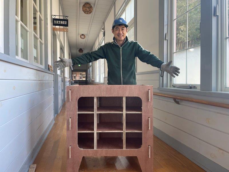
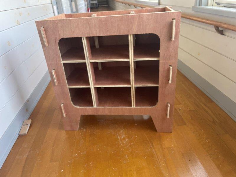
Make (design+mill+assemble) something big (~meter-scale) extra credit: don't use fasteners or glue extra credit: include curved surfaces
- I made below without using fasteners or glue.
3D data with Solid Works
- This time I tried Solid Works as 3D CAD.
-
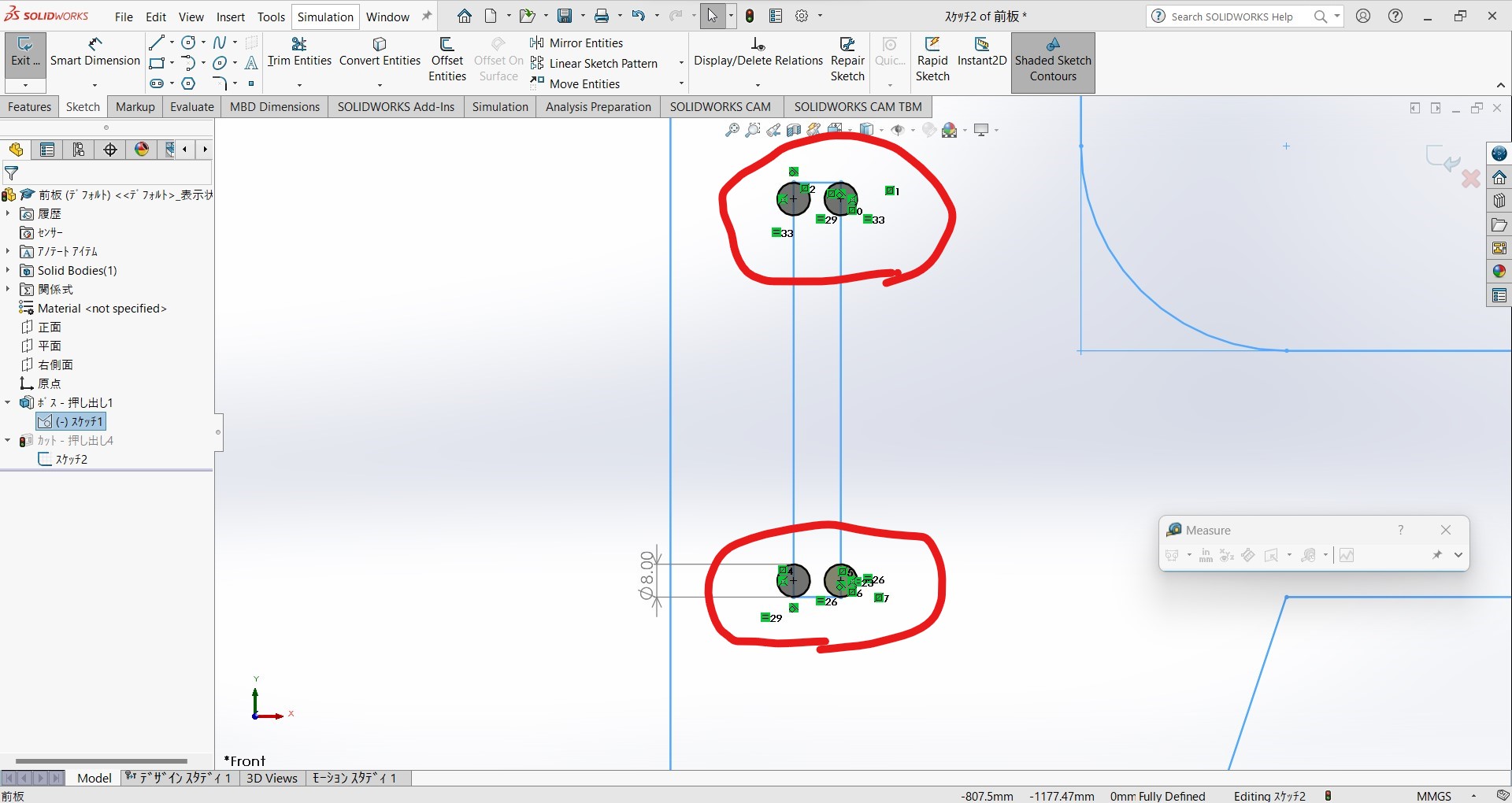
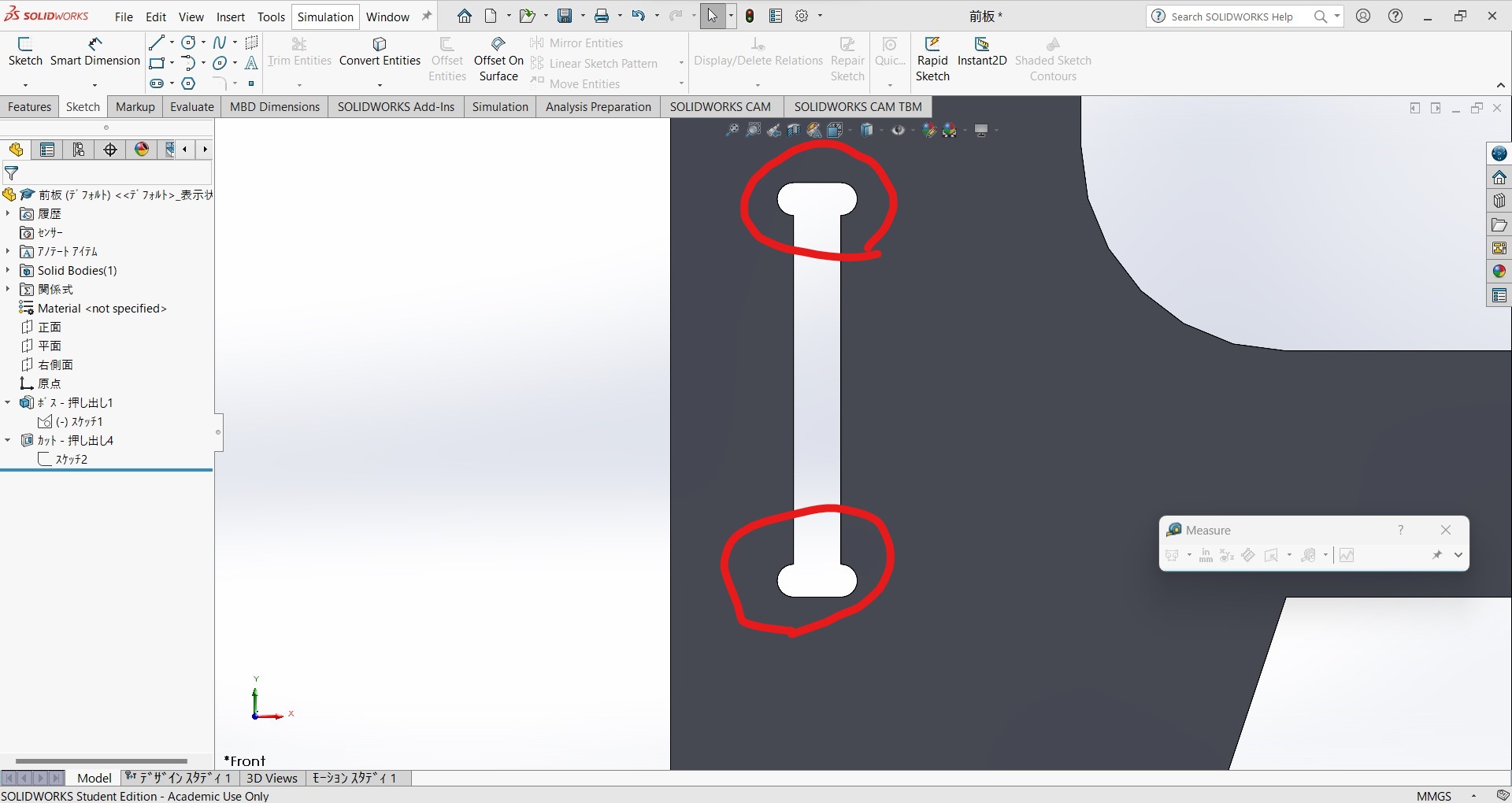
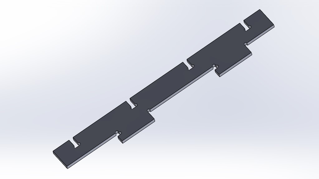
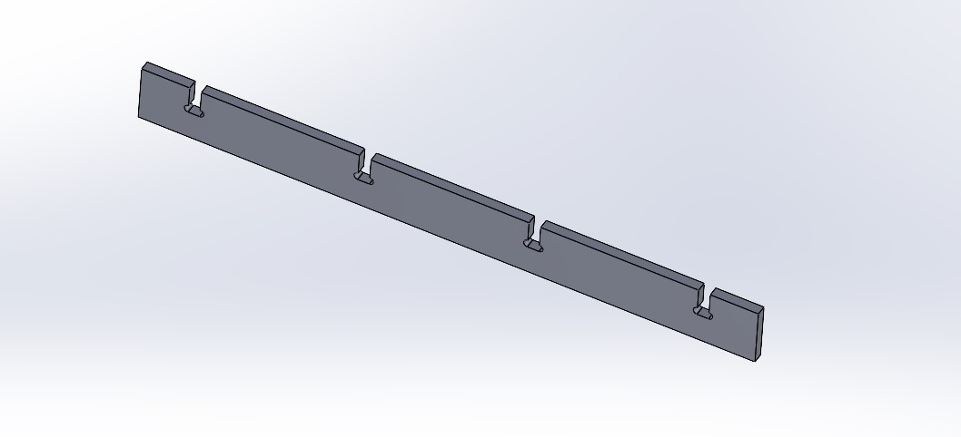
Tools are rolling, so it is impossible to draw 90 degree curve without dog bone. I must check all 90 degree curve must have dog bone before sending CAM process. This time for making dog bones, I did just add circles where it needs. Diameter of the circle must be bigger than end-mill's.
-
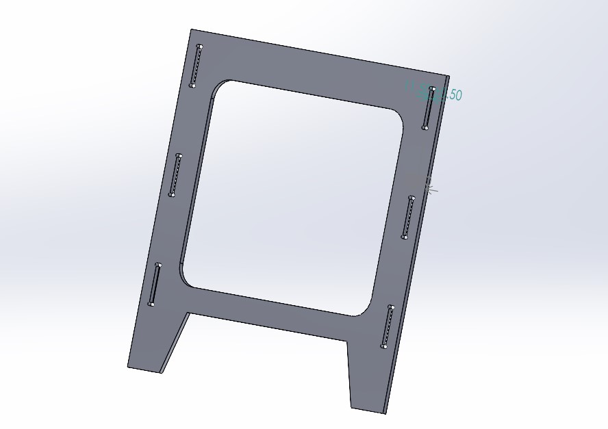
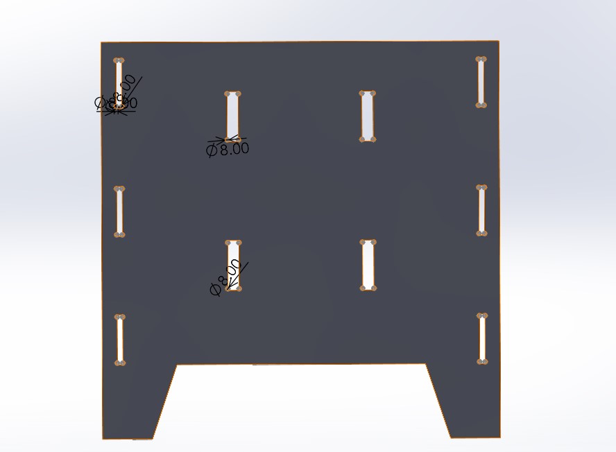
Assembly function explained in (week2 document) It is important to check my designs are possible to set up.
-
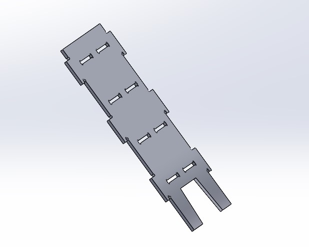
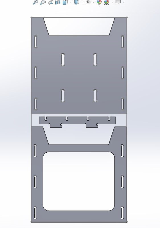
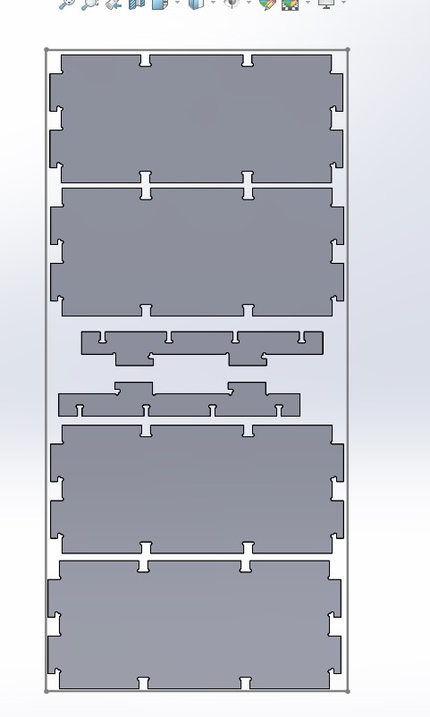
I made parts of 7 kinds. (original data by Solid Works,board1 board2)
-
Then assembled. I studied assembling on Solid Works at week 2
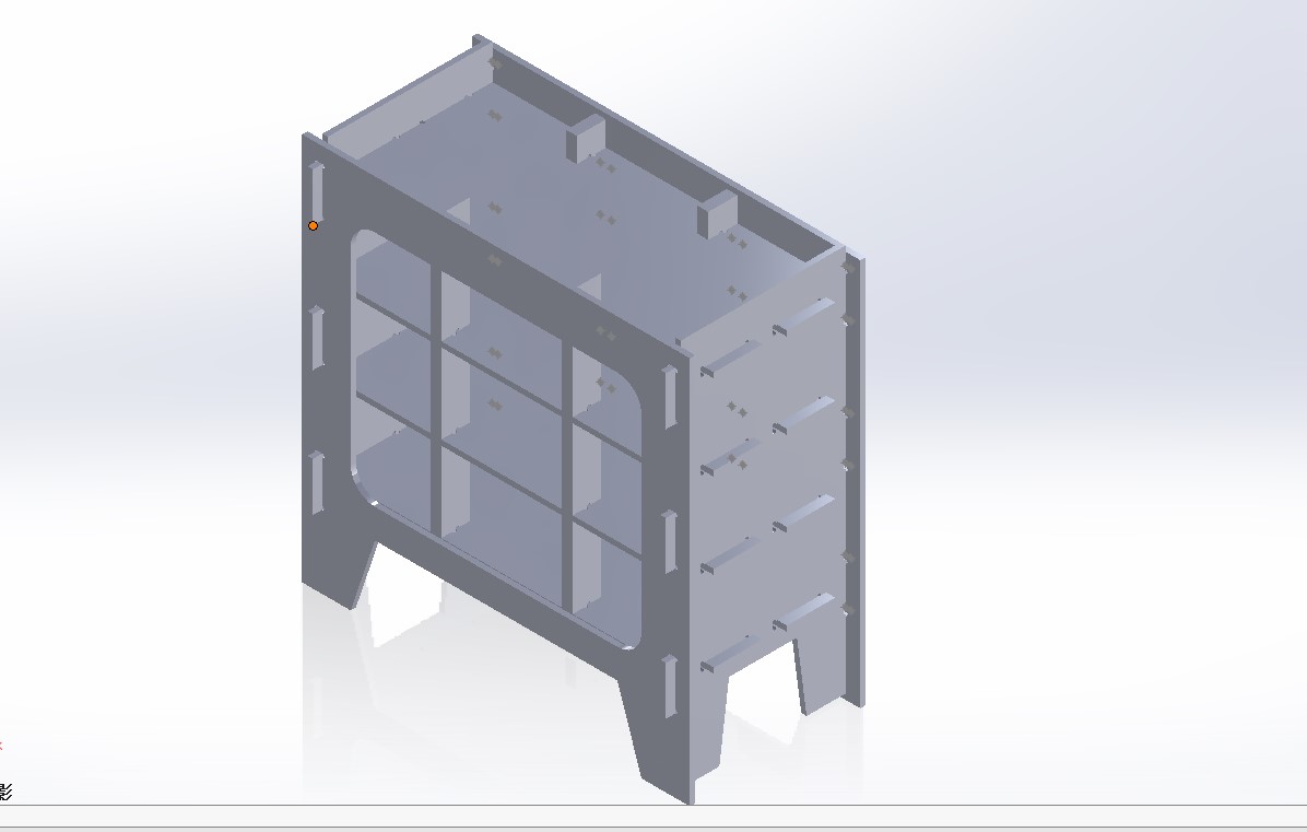
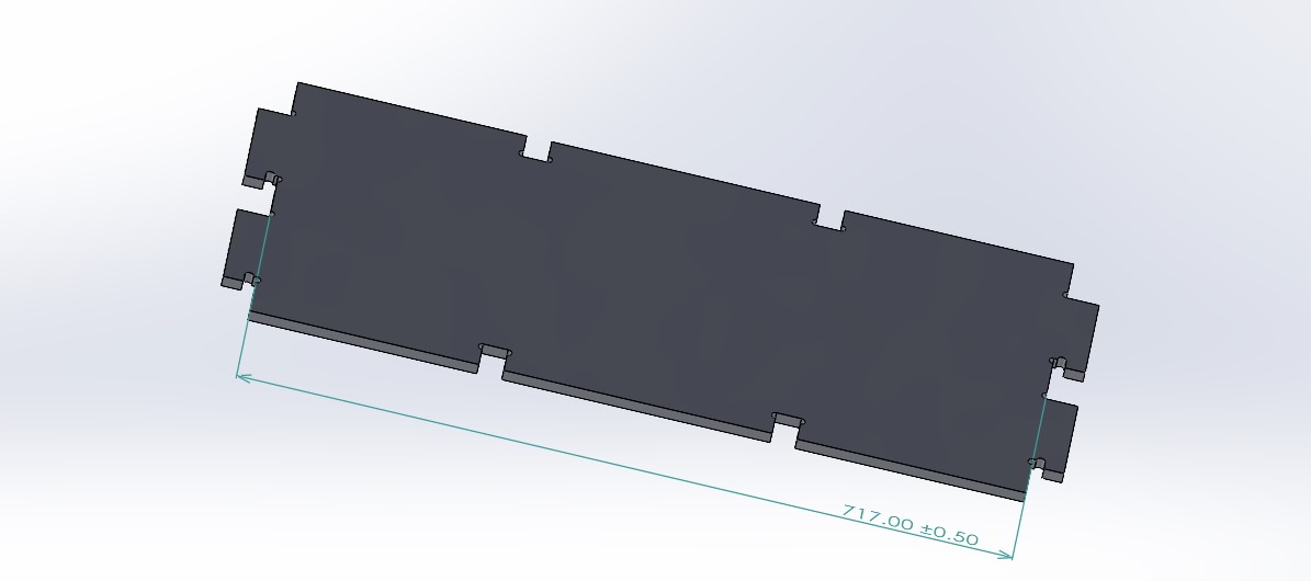
- With assemble function I can allocate the parts by mate function all parts on the same flat level and measure function possible to check the parts area is smaller than the stock size.
Fusion 360 as CAM
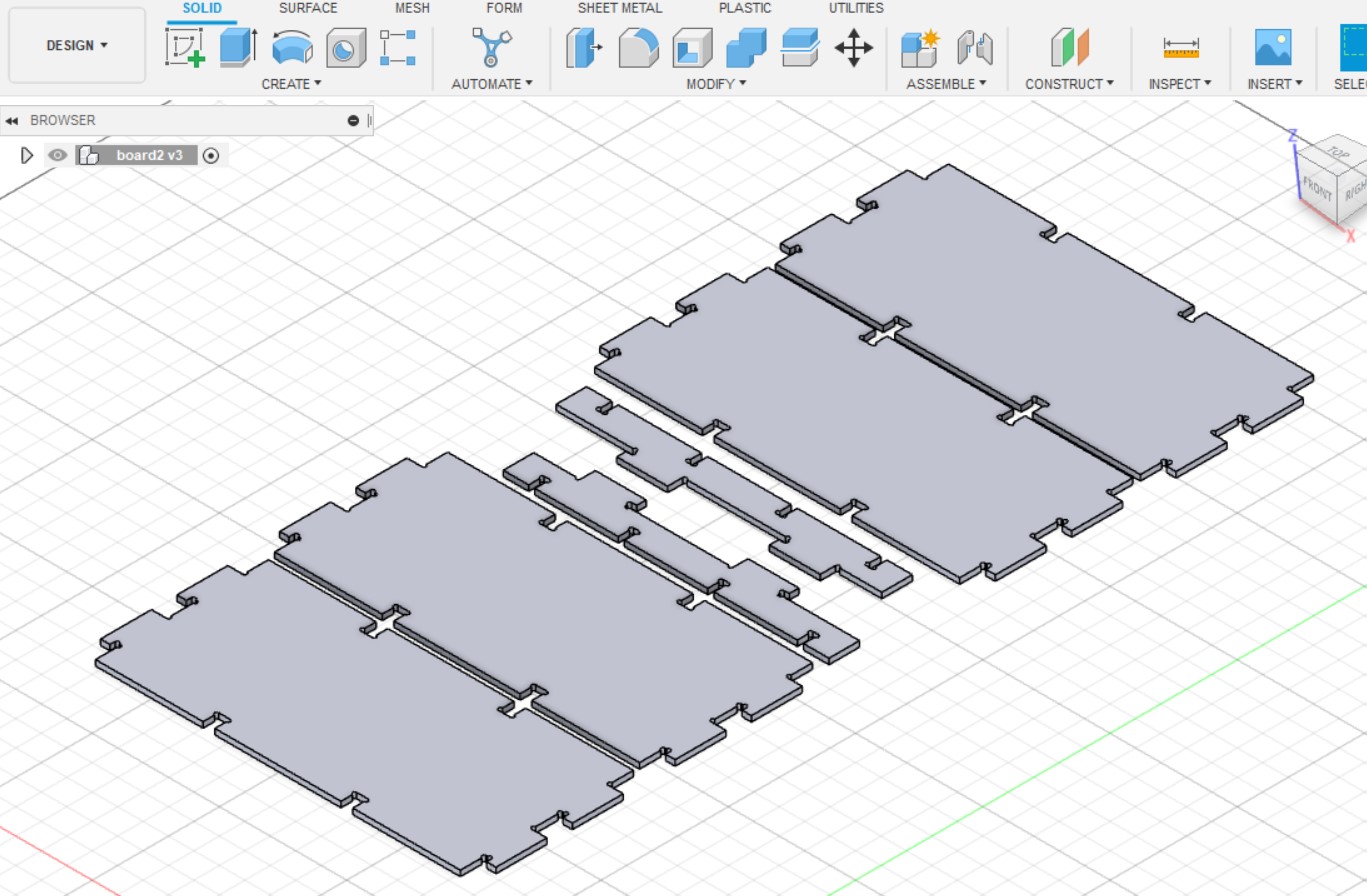
- As my Solid Works license does not allow CAM function, I export step data and import into Fusion 360. (original data with Fusion 360)
- I learnt CAM function of Fusion 360.
- Laid out the 3D data in the board size.
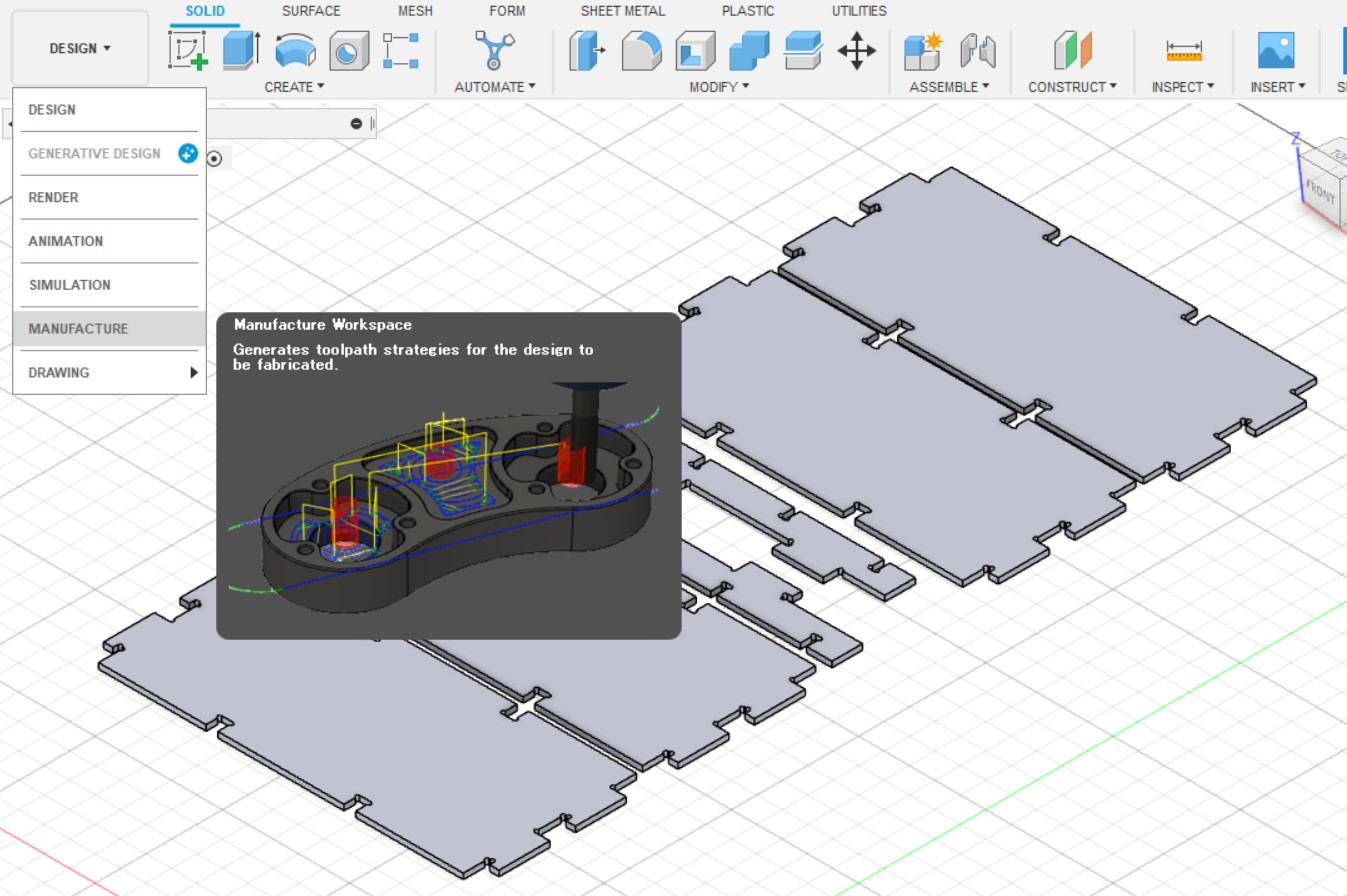
- I enter "Manufacture" tab.
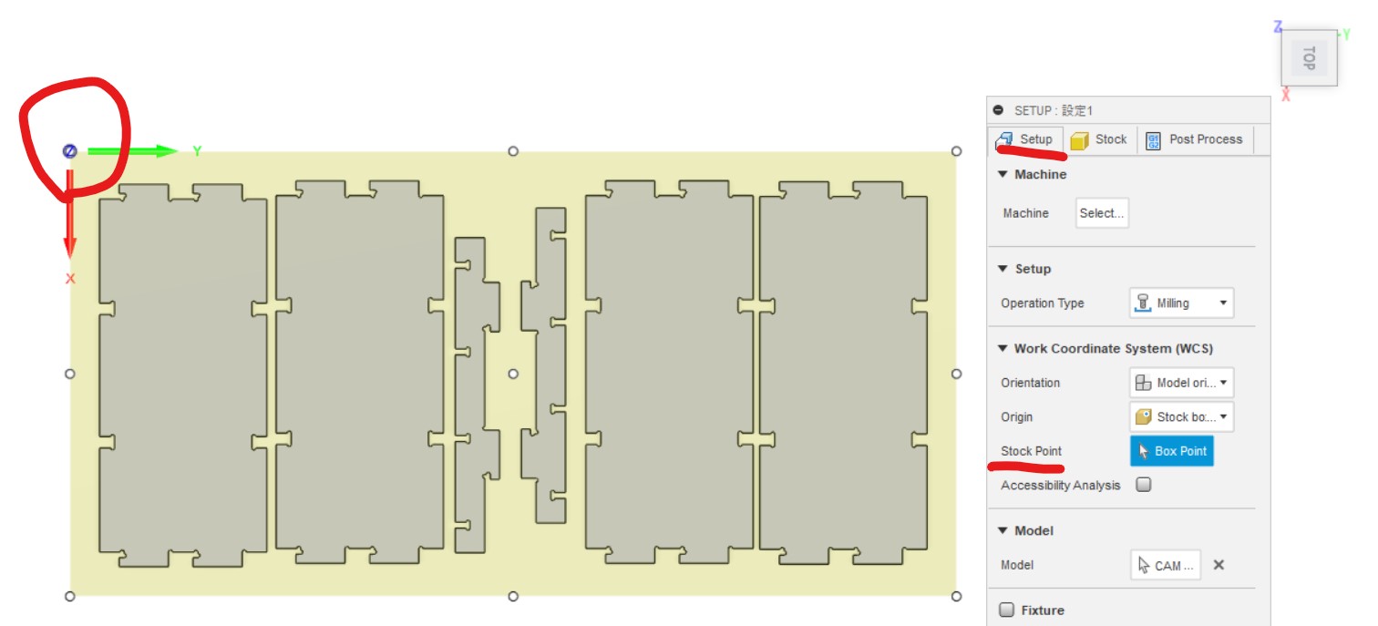
- Click "SETUP"->"New Setup" to adjust parameters. At first I set stock size by inputting stock offset. This time I prepared ply-wood boards 1800x900x11 mm.
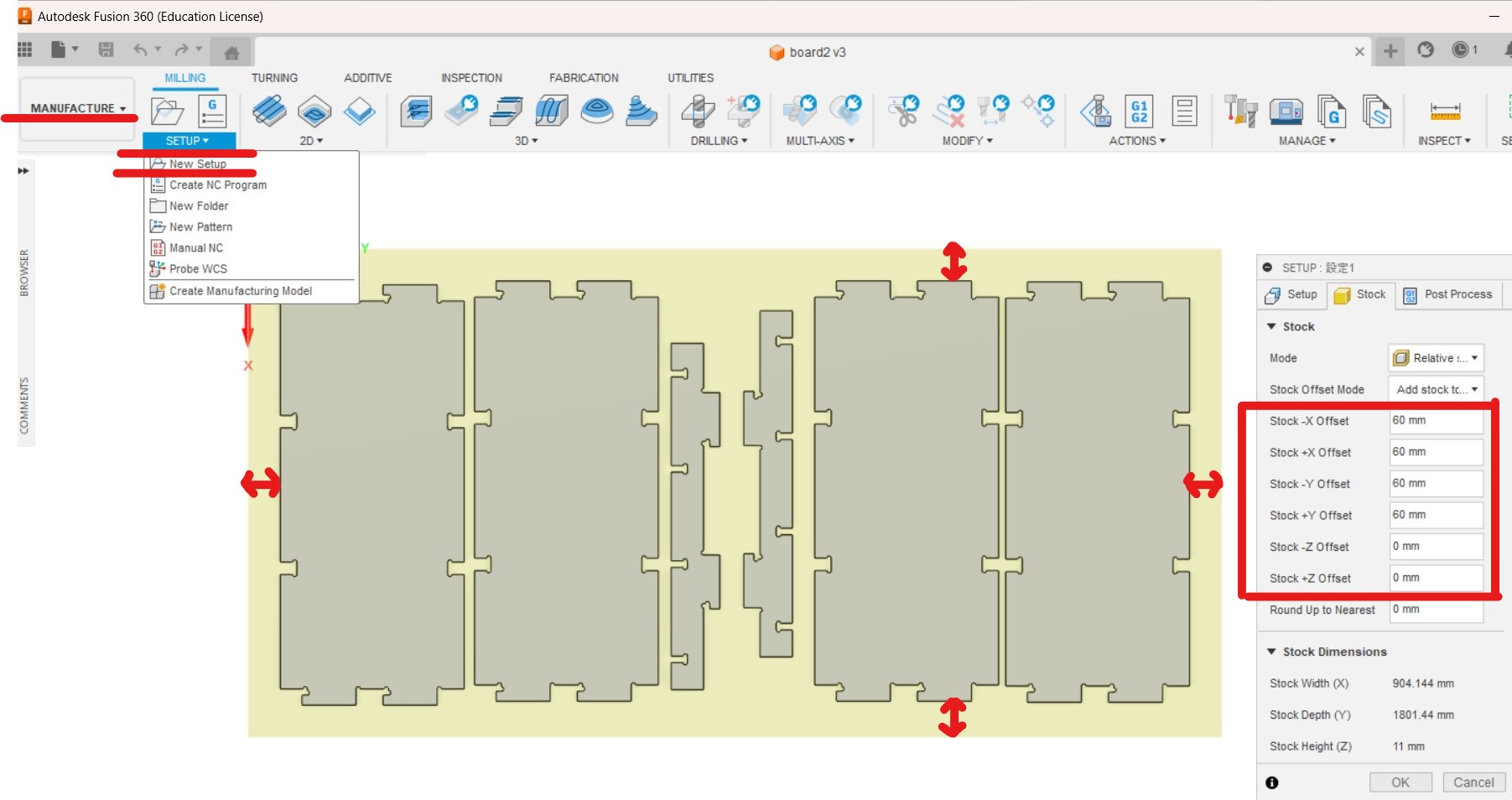
Now there are 60 mm spaces out of parts design, this space can be used for fixing the stock. -
Set "Stock Point" as origo, I need to click exact xyz=(0,0,0) point. Especially be careful for z (top or bottom of the stock) setting. Below picture shows bottom of the stock as z=0.
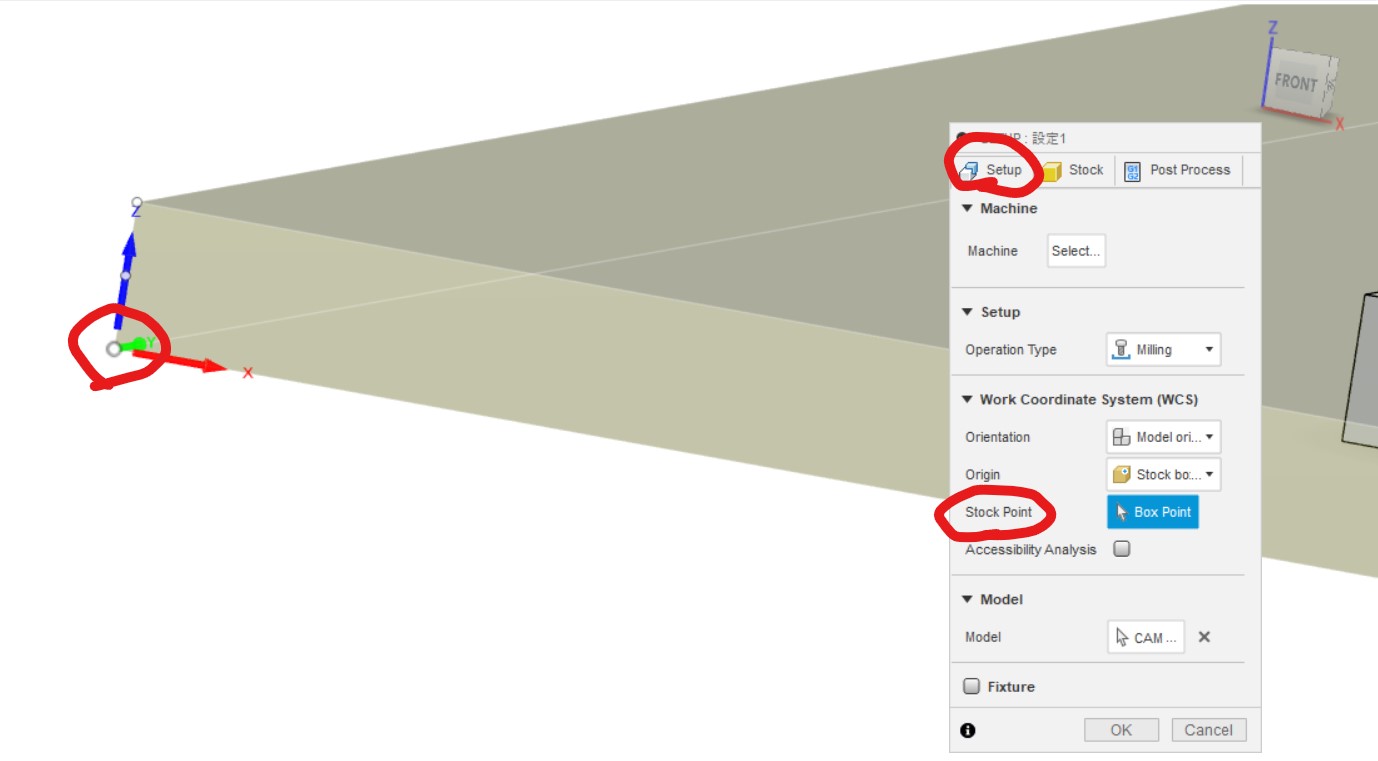
View from above (xy=0,0 setting)
-
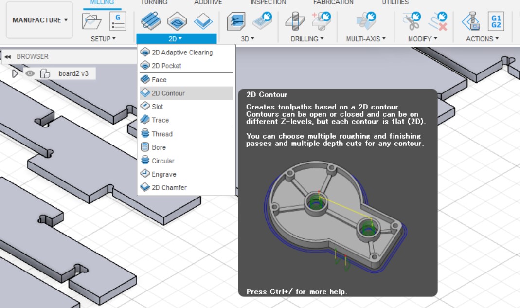
Move to "2D Contour" tab for tool and cutting work settings
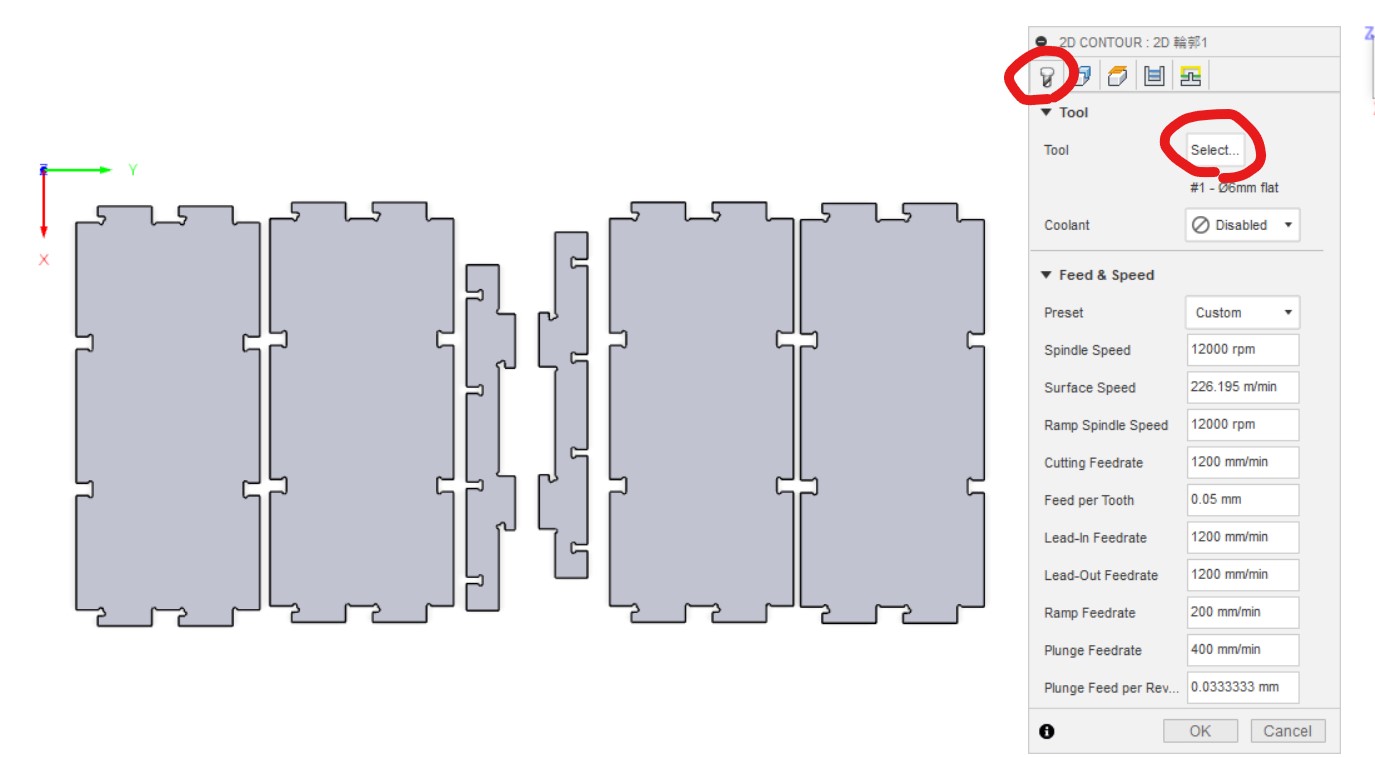
- Click "Tool"->"Select" to open mill setting window.
- Once selected the mill, right click and select "Edit tool" to set parameter of the tool.
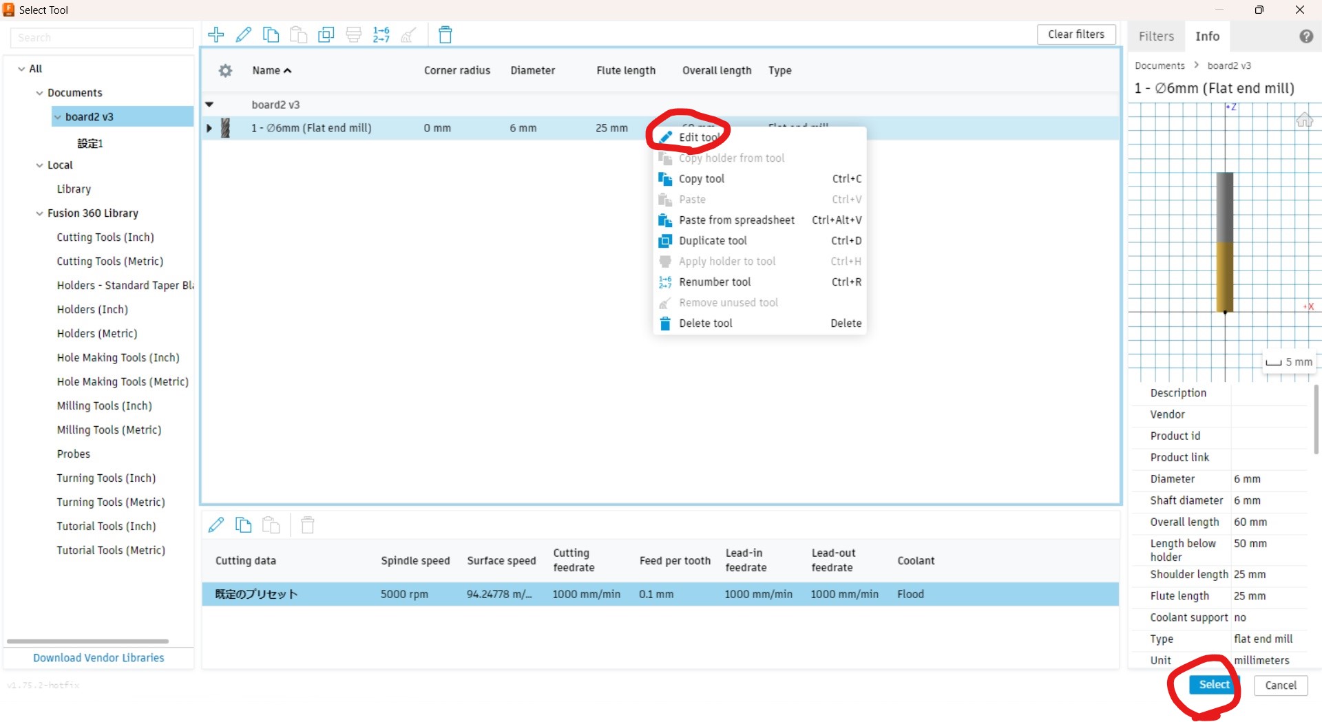
- Tool parameter window pops up. Then I can set number of flutes etc. based on actual tool I use for this work.
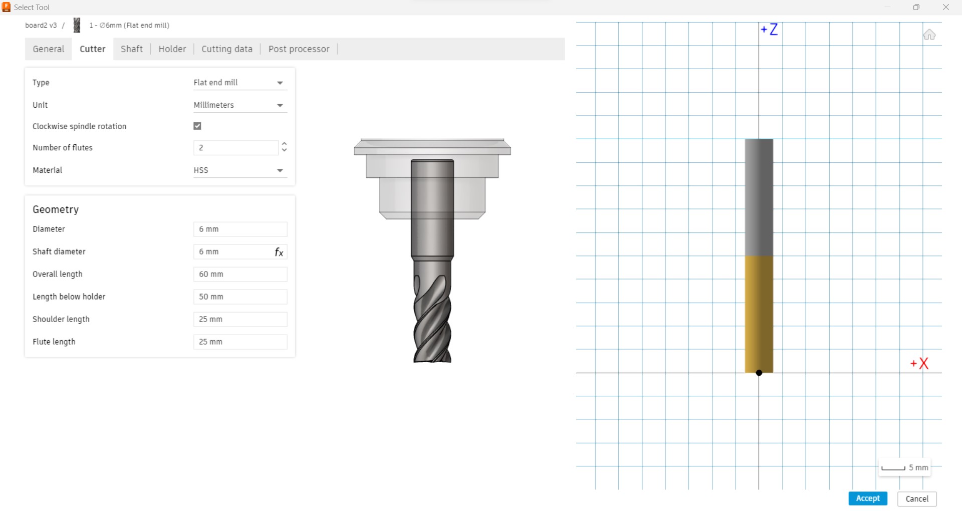
-
After tool setting come back to "2D CONTOUR" window. And set work speed. This time cutting speed bit faster to see such rate is possible for 11mm ply wood. (This CNC is newly designed built just a week ago, so wanted to try many cases)
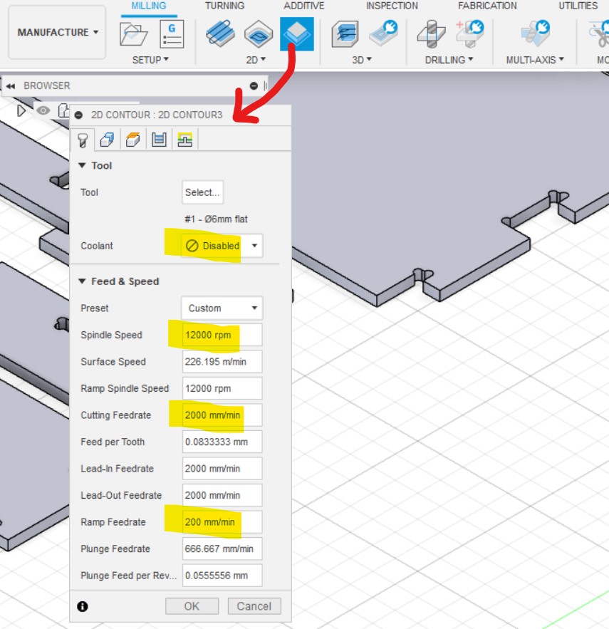
-
I can set "tab" for safely cutting. Tabs keep the parts stable. But too many tab causes too many work after cutting.
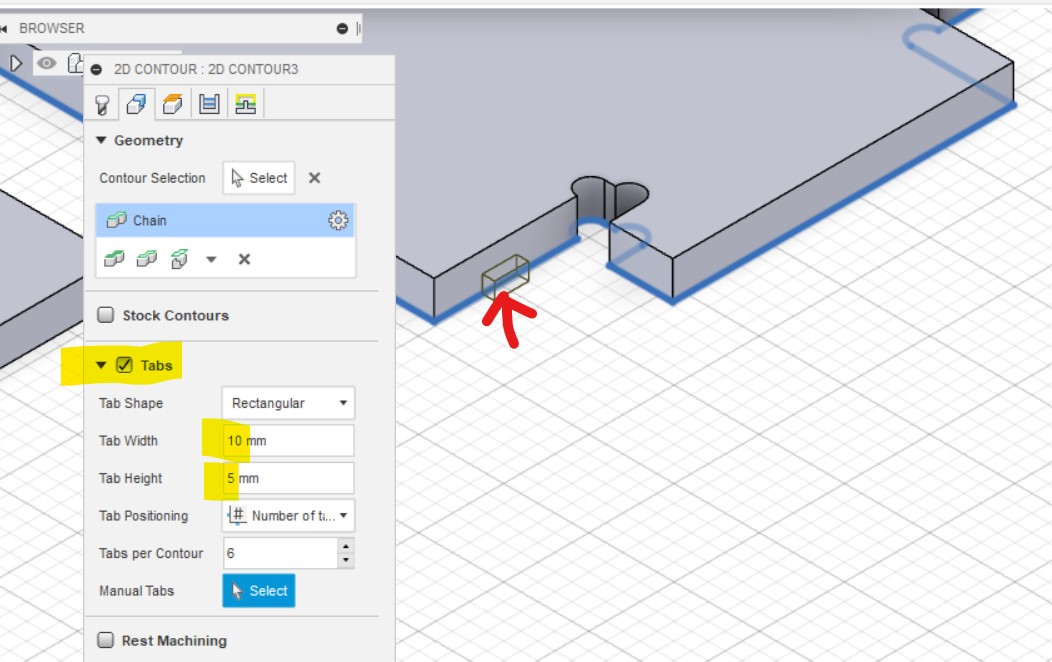
- Kept default setting for heights.
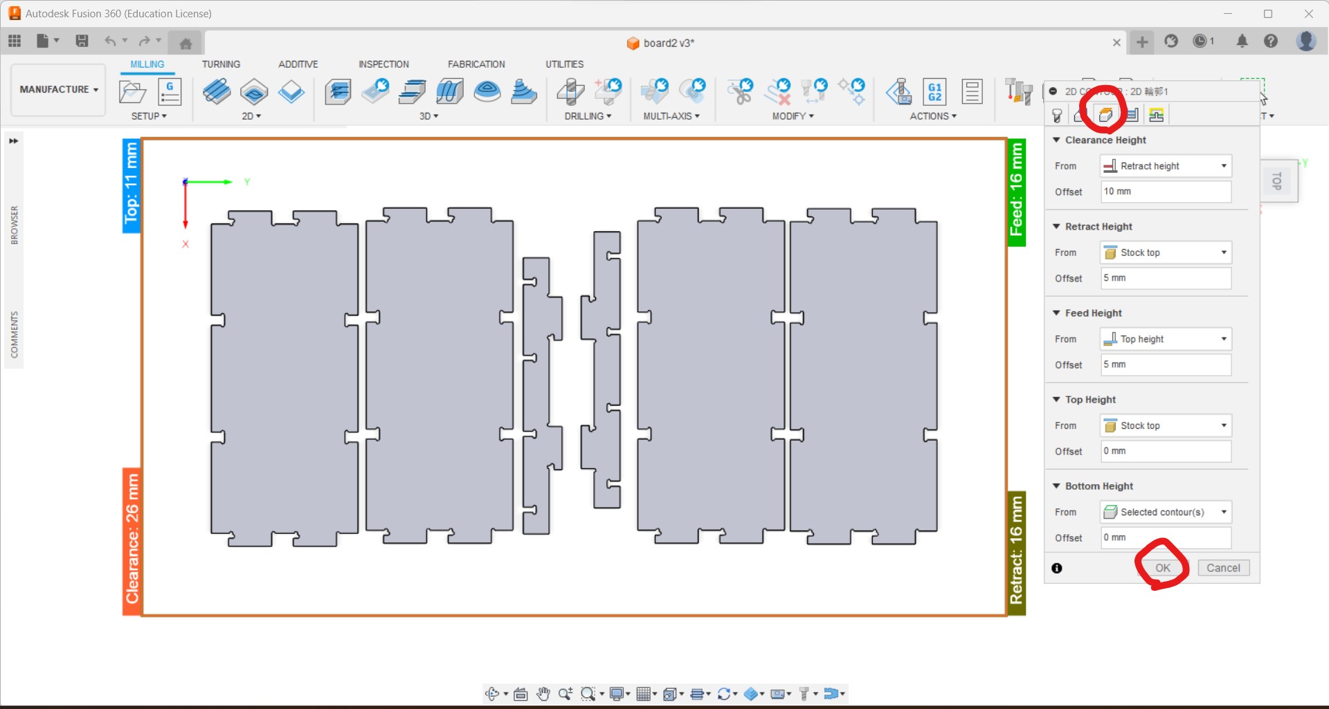
-
Step down can be set, roughing step down and finishing step down.
-
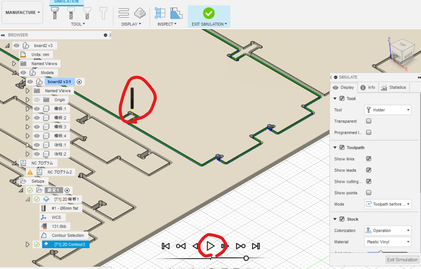
Once complete the setting, I can see the simulation.
- Then I can export the tool path data from "Post Process"
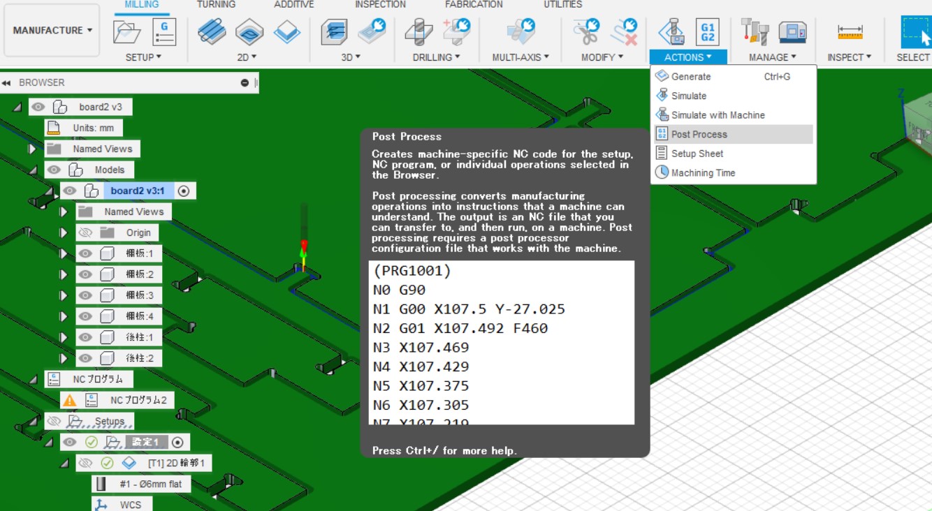
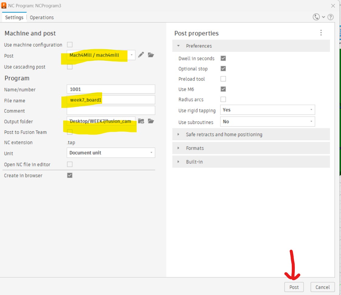
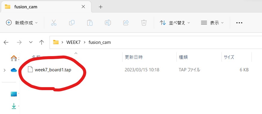
- The tool path is exported a .tap file.
Mach4
- Actual controlling of the machine is done with Mach4.
- This reads tool path data, and also set the 0 positions of x, y and z axial.
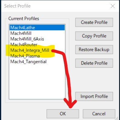
- For our CNC we choose "Mach4 Integra_Mill"
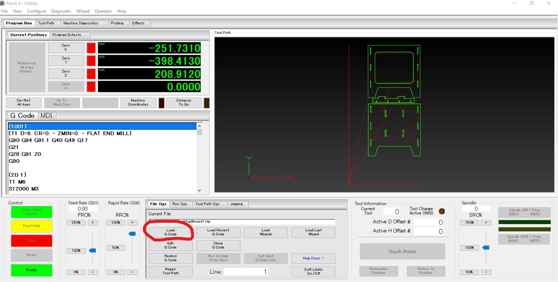
- Import the tool path data (.tap file from fusion 360) with "Load G code"
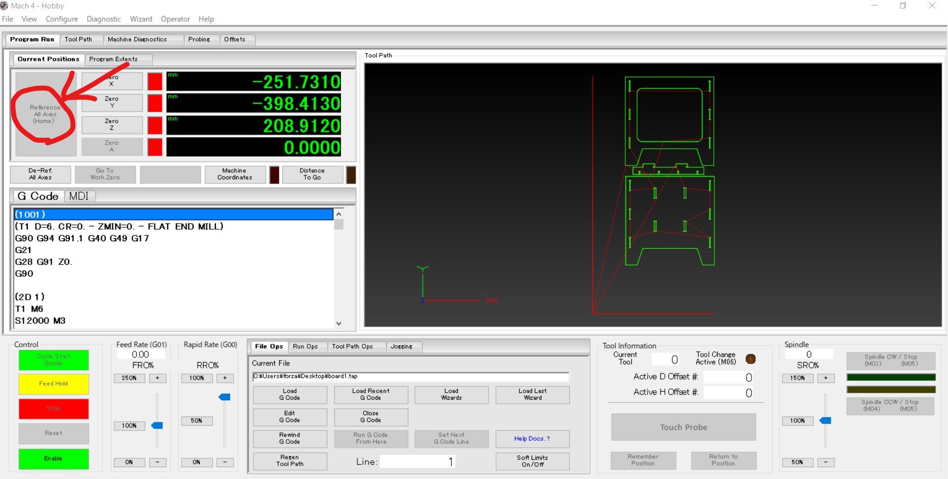
Setting origin point
- By pressing "Reference All Axes (Home)", the spindle moves to global origin point.
-
Next set Z work origin point with setting touch probe and pressing "Touch Probe"
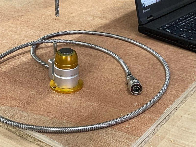
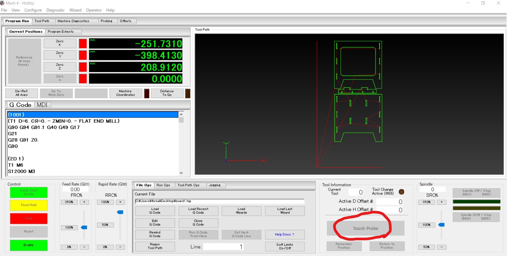
-
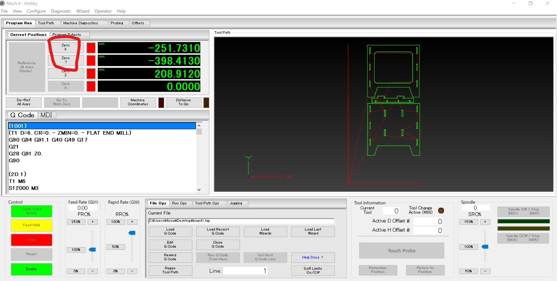
Move the spindle to X,Y work origin and set XY origin by pressing "Zero X" and "Zero Y".
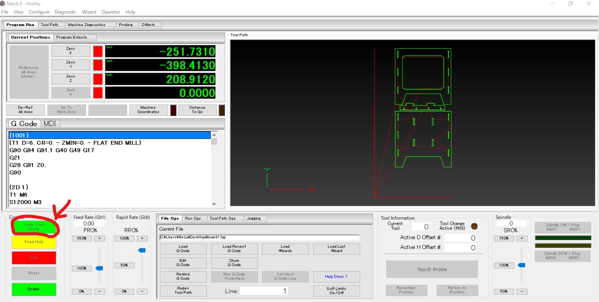
- After confirming the mill is correctly set and dust cover set, I can start cutting by pressing "Cycle start Gcode"
Cutting
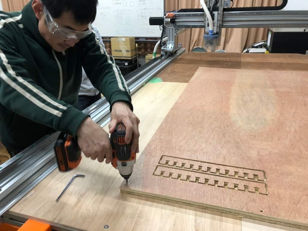
- I must wear eye protection.
- Fix the board on to CNC, we used screw nails. The offset space (60mm from outline) is for screw nails.
- Cut 1 cycle in the air (z is enough high) for checking the actual route is as expected.
- Be ready for pushing stop button. In case of emergency.
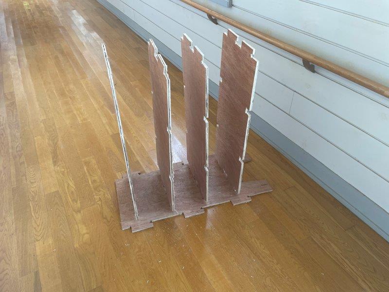
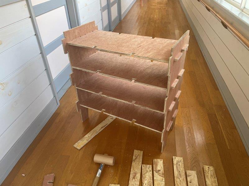
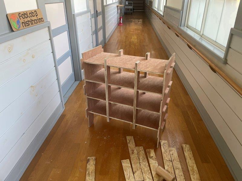
Assembly
- Once the cutting done, I removed the tabs.
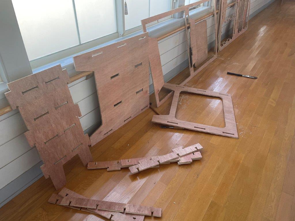
- Edges are smoothened by sanding paper. Then assemble start.
Thoughts and feelings
- CNC is fantastic machine, and has the complicated settings and data handling. I found 3 steps like creating 3D model, set up in CAM and actual control of the machine. It sounds overwhelming but I managed to complete the cutting if I learn part by part.
- This time I wanted try Vcarve Pro as well, but once I complete the tool path, it turned out the path takes too long time (Vcarve showed 5hours for the same 30 minutes in fusion 360 CAM) the reason to be checked out.
Note from chat GPT
I asked general question to Chat GPT and got answers as below.
What is CAM
CAM stands for Computer-Aided Manufacturing, which is a software tool used in machining to generate the program that controls the CNC machine.
CAM software takes the computer-aided design (CAD) model of a part and generates the toolpaths and instructions that the CNC machine needs to produce the part. This involves specifying the cutting tools to be used, the cutting parameters, the sequence of operations, and other details that are necessary for the CNC machine to execute the manufacturing process.
CAM software can help improve machining efficiency and accuracy by automating many aspects of the manufacturing process, including toolpath generation, optimization of toolpaths to minimize tool wear and improve surface finish, and simulation of the machining process to identify and correct errors before production.
Some common features of CAM software include:
- 2D and 3D modeling tools to create the geometry of the part to be machined
- Automatic toolpath generation based on user-defined parameters and cutting tool specifications
- Simulation and verification tools to visualize the machining process and detect potential errors or collisions
- Post-processing capabilities to generate machine-specific G-code for CNC machines to execute
- Integration with other CAD and manufacturing software tools to streamline the overall production process.
MACH4
MACH4 is a computer numerical control (CNC) software that is used for controlling and operating CNC machines. It is developed by Newfangled Solutions LLC and is designed to work with a range of CNC machines, including mills, lathes, routers, plasma cutters, and water jet cutters.
MACH4 provides a wide range of features that enable users to create and execute complex machining operations with precision and efficiency. Some of its key features include:
- Intuitive interface: MACH4 has an easy-to-use interface that allows users to navigate through the software and operate their machines with ease.
- Customizable workspaces: Users can customize their workspaces to suit their preferences and create custom macros and scripts for specific machining tasks.
- G-code programming: MACH4 supports standard G-code programming, allowing users to create and edit CNC programs directly within the software.
- Toolpath simulation: MACH4 provides a toolpath simulation feature that enables users to preview their machining operations before executing them, reducing the risk of errors and minimizing material waste.
- Advanced motion control: MACH4 supports advanced motion control features such as tool radius compensation, spindle synchronization, and multi-axis simultaneous motion.
Comparison Vcarve Pro and Fusion 360
Vcarve Pro and Fusion 360 are both popular Computer-Aided Manufacturing (CAM) software programs used in the machining industry. While both programs are designed to generate toolpaths for CNC machines, they differ in their functionality and capabilities.
Vcarve Pro is a more specialized CAM program that is primarily focused on 2D and 2.5D machining. It is particularly well-suited for creating toolpaths for carving and engraving operations. Some of its key features include:
User-friendly interface: Vcarve Pro has an easy-to-use interface that makes it simple for users to create toolpaths for 2D and 2.5D machining operations.
Vector-based design tools: Vcarve Pro's design tools are vector-based, making it easy to create precise geometries and shapes.
V-carving functionality: Vcarve Pro has specialized tools for V-carving, which are particularly useful for engraving and carving operations.
Cost-effective: Vcarve Pro is a more cost-effective solution compared to some of the more advanced CAM software programs on the market.
Fusion 360, on the other hand, is a more powerful and versatile CAM software program that is capable of handling both 2D and 3D machining operations. It is a cloud-based program that offers a wide range of design and simulation tools in addition to its CAM functionality. Some of its key features include:
Advanced design and simulation tools: Fusion 360 includes advanced design and simulation tools that allow users to create and simulate complex parts and assemblies.
Integrated CAD and CAM functionality: Fusion 360 integrates CAD and CAM functionality in a single program, making it easy to transition from design to manufacturing.
Cloud-based: Fusion 360 is a cloud-based program that offers collaborative tools for team-based design and manufacturing projects.
Large community: Fusion 360 has a large and active user community that provides support, resources, and tutorials.
Overall, while Vcarve Pro is a more specialized program focused on 2D and 2.5D machining operations, Fusion 360 is a more powerful and versatile program that offers advanced design and simulation tools, integrated CAD and CAM functionality, and cloud-based collaborative features. The choice between the two programs ultimately depends on the specific needs and requirements of the machining project.