Week 03 Computer-Controlled Cutting
a) Description of the week
- Prof. Neil explained various cutting method and tools(hard and soft).
- As recitation advanced designing methods and tools(software) are introduced. Including use of AI.
b) Task of the week
- Group assignment: characterize your laser cutter's focus, power, speed, rate, kerf, joint clearance and types
- individual assignment: cut something on the vinyl cutter design, lasercut, and document a parametric construction kit, accounting for the laser cutter kerf, which can be assembled in multiple ways, and for extra credit include elements that aren't flat Plan and sketch a potential final project
1. Group assignment
c1) Result
d1) Thoughts and feelings
-
From this week I started actual machine operation, it is fun. At the same time I need to consider safety issue as below;
- Be careful the material so that hazardous gas might be generated. Never ever try to cut PVC. This site organizes such DON'T materials.
- Be careful of fire. For this I must stay nearby the machine till the work end. Once the material started burning, I must turn off all the power switches relating the machine.
- Wear glasses to protect my eyes.
-
I understood each machine has each character, so it is important to know it and take it into cutting data. Otherwise I cannot cut as I draw in the data. Our instructor told age of the machine also affects, so if you changed any parts of the cutter, the character would be changed.
-
Even if I operate properly, the machine causes trouble. For example when I started the laser cutter, the instructor told “Stop now, the belt might be slipping! ” he recognized it by the sound. If someone could not detect it, the work would be failure.
2. Individual assignment
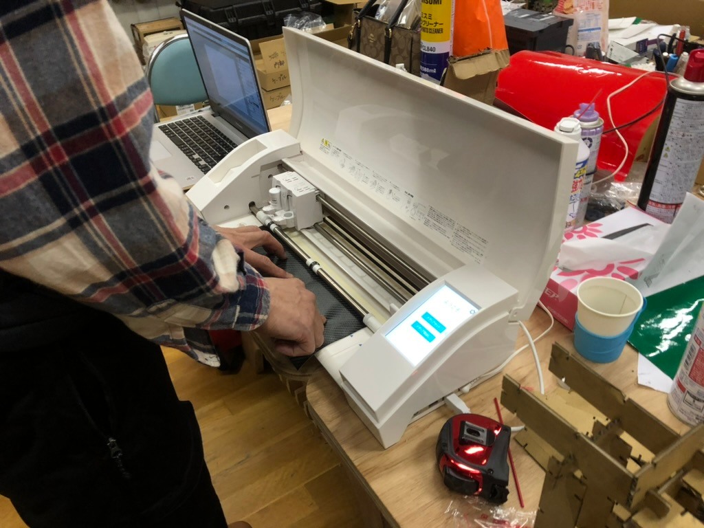
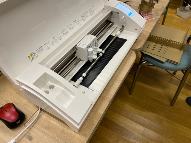
2-1 Vinyl cutter
c2-1) Result
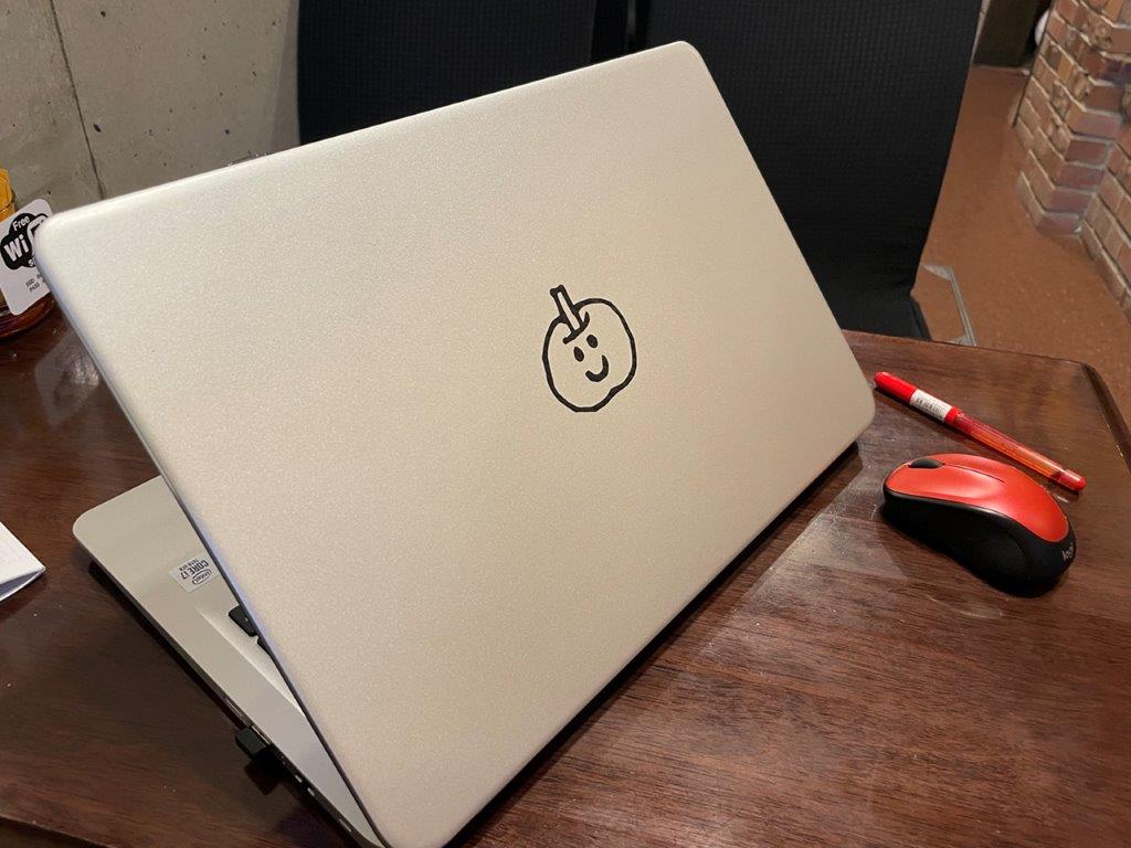
I made below sticker with a vinyl cutter "CAMEO 3".
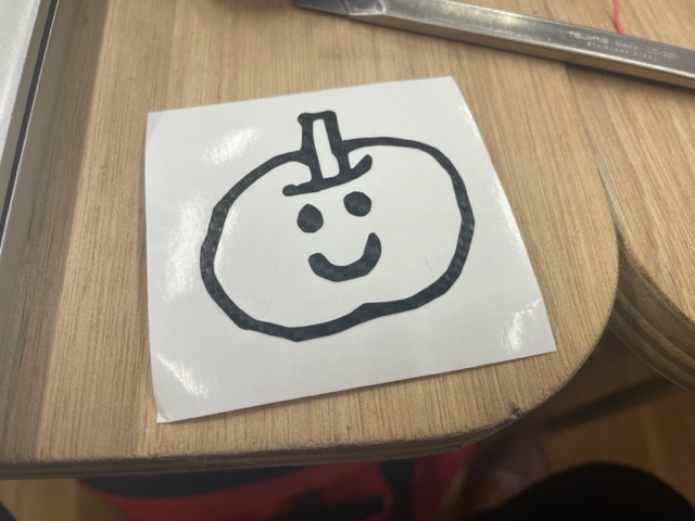
d2-1) Process for the result
-
I used below dxf data for cutting. (original file .dxf)
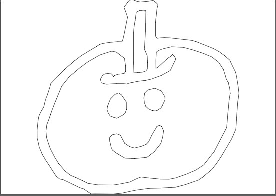
-
As preparation, installed "silhouette studio 4.5 basic edition"
- Imported the dxf data into silhouette studio, then adjust the settings.
- Blade Depths:3
- Pass:1
- Force:15
- Speed:10
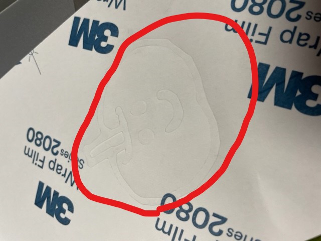
This time I am cutting 3M Wrap Film Series 2080 , then I was recommended the strong setting as above.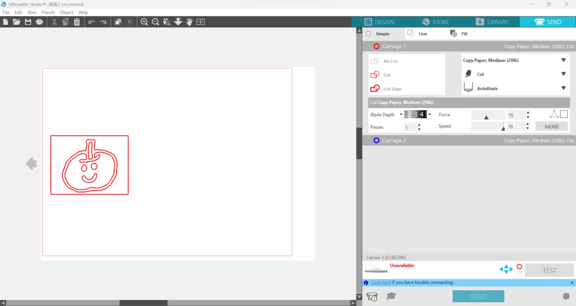
-
Sheet setting
- I just set the sheet and keep by hands, did not use mat.
- I just set the sheet and keep by hands, did not use mat.
-
Cutting
After cutting, I checked back side then I saw sticker mat was also cut, it means the force and blade depth was strong.
-
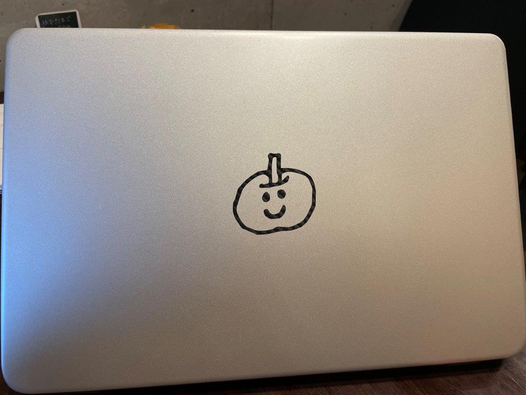
Transfer
- Put a transfer sheet on it
- Carefully stick it on the target (this time my PC)
- Press enough
- Carefully remove the transfer sheet
e2-1) Thoughts and feelings
- This was the first time I use vinyl cutter and now I am able to use our lab's vinyl cutter.
- When I cut thick sheet like sticker, I need to be careful if the sheet rolled. Because in such case the sheet is not flat that the curl of the roll might interrupt the machine work.
- The appropriate setting differs for each type of sheet. So better to start with weaker setting then gradually raise.
2-2 Parametric construction kit
c2-2) Result
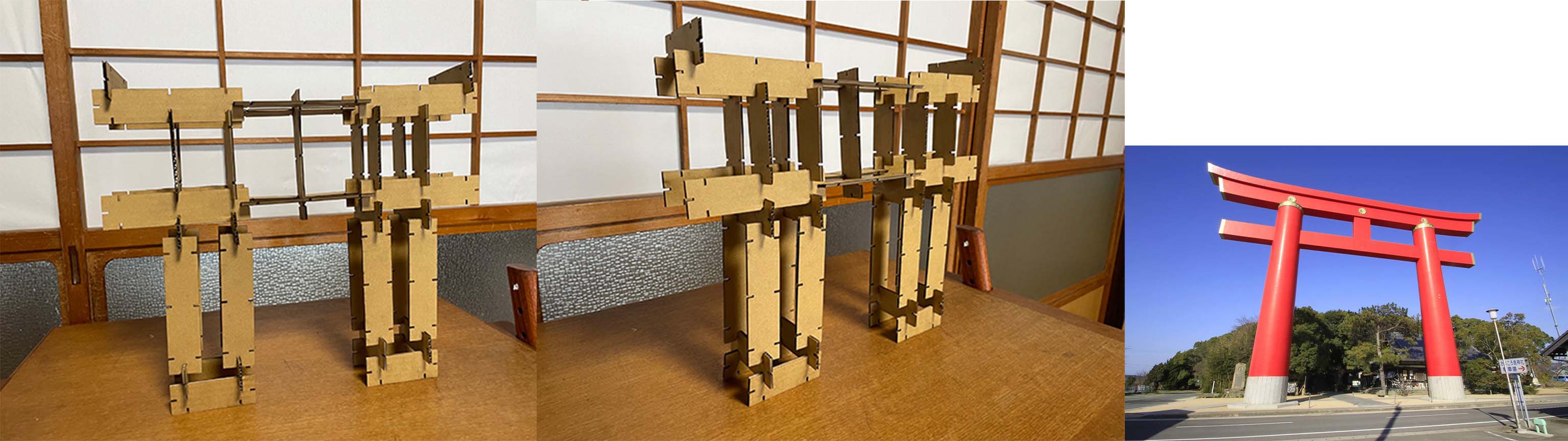
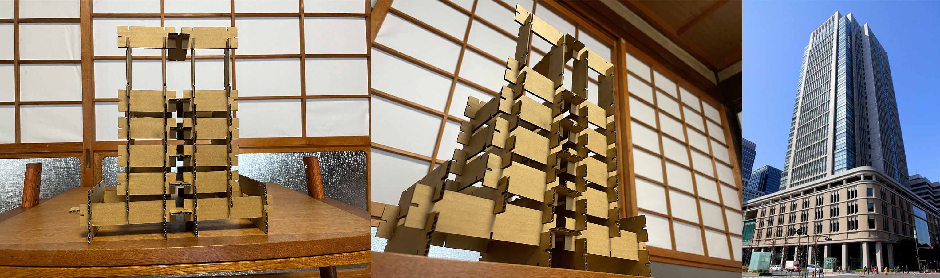
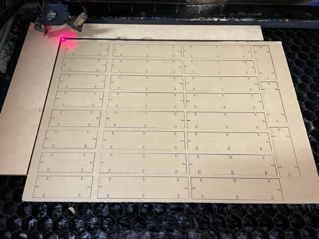
I made below construction kit with parametric design with our lab's laser cutter "FABOOL laser CO2"
Torii(Gantry like gate of Japanese shrine)
Marunouchi Building
d2-2) Process for the result
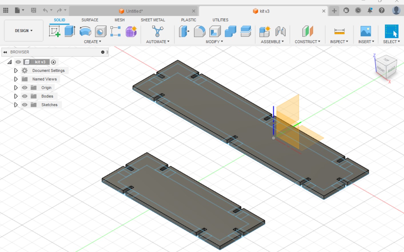
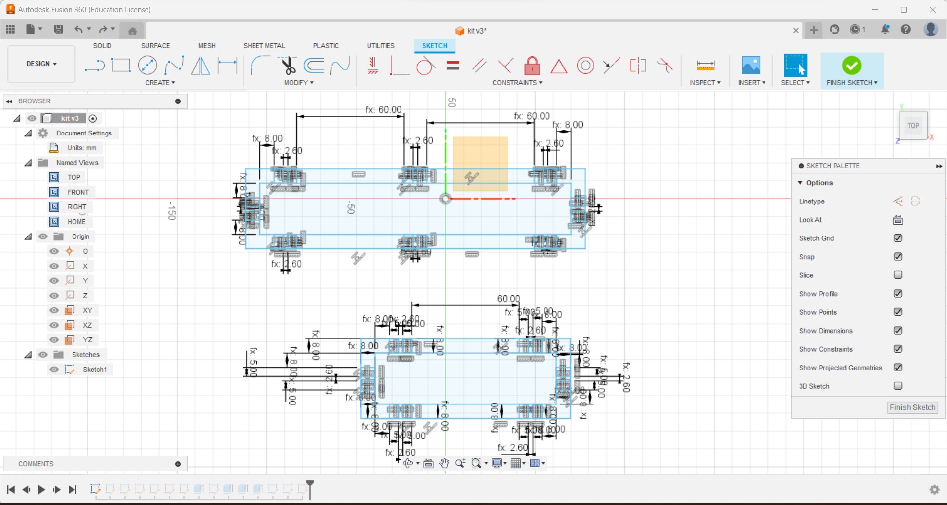
Parametric design with fusion 360
-
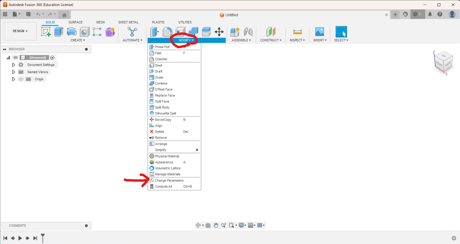
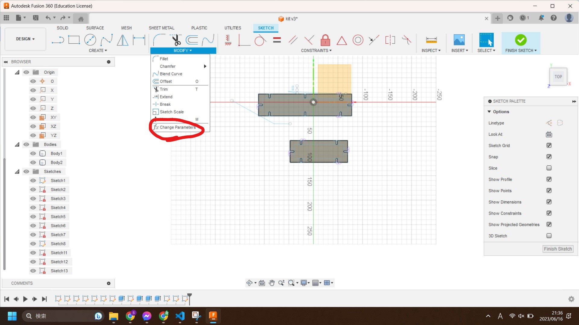
On Fusion 360, I can open parameter window by clicking "Modify" -> "Change Parameters"
-
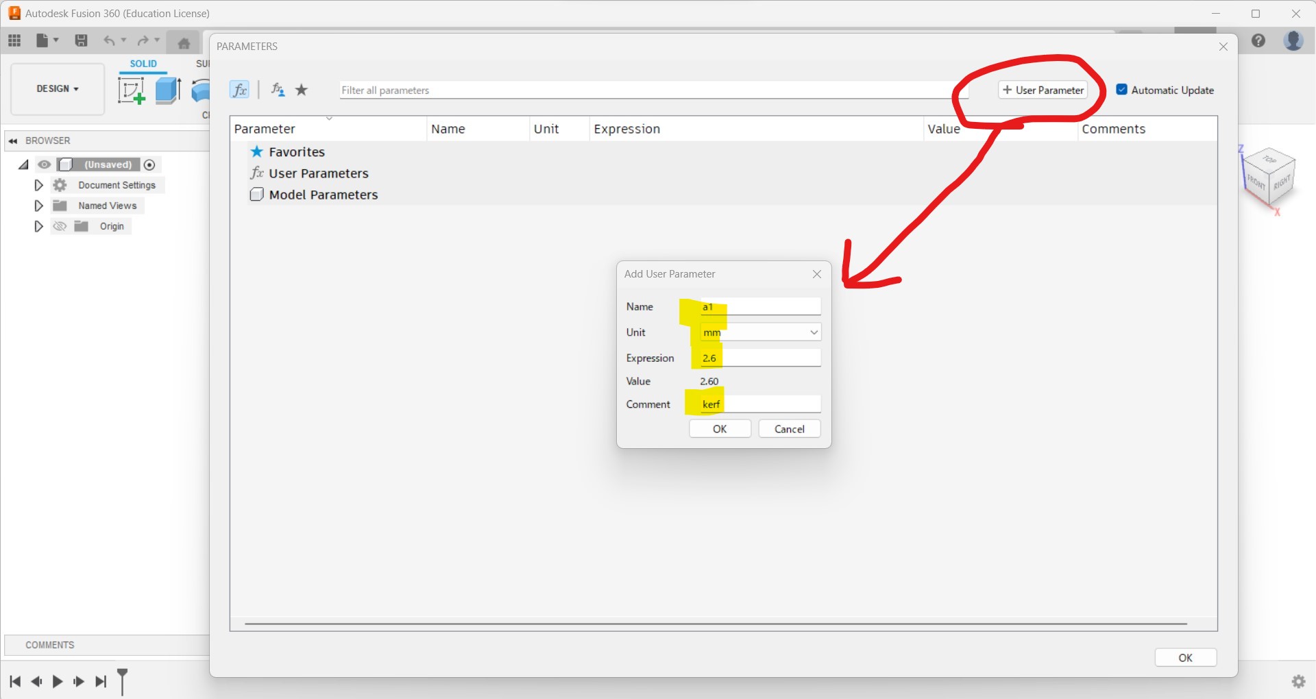
On parameter window, I can set my own parameters by clicking "+ User Parameter"
-
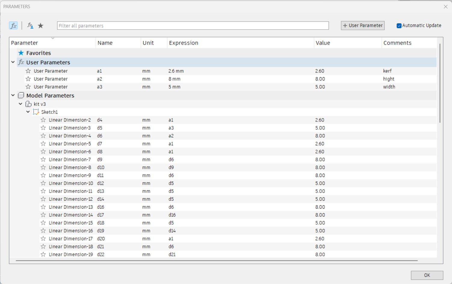
Once parameters set, I can use them in the sketch. I can refer which part use which parameter through parameter window.
-
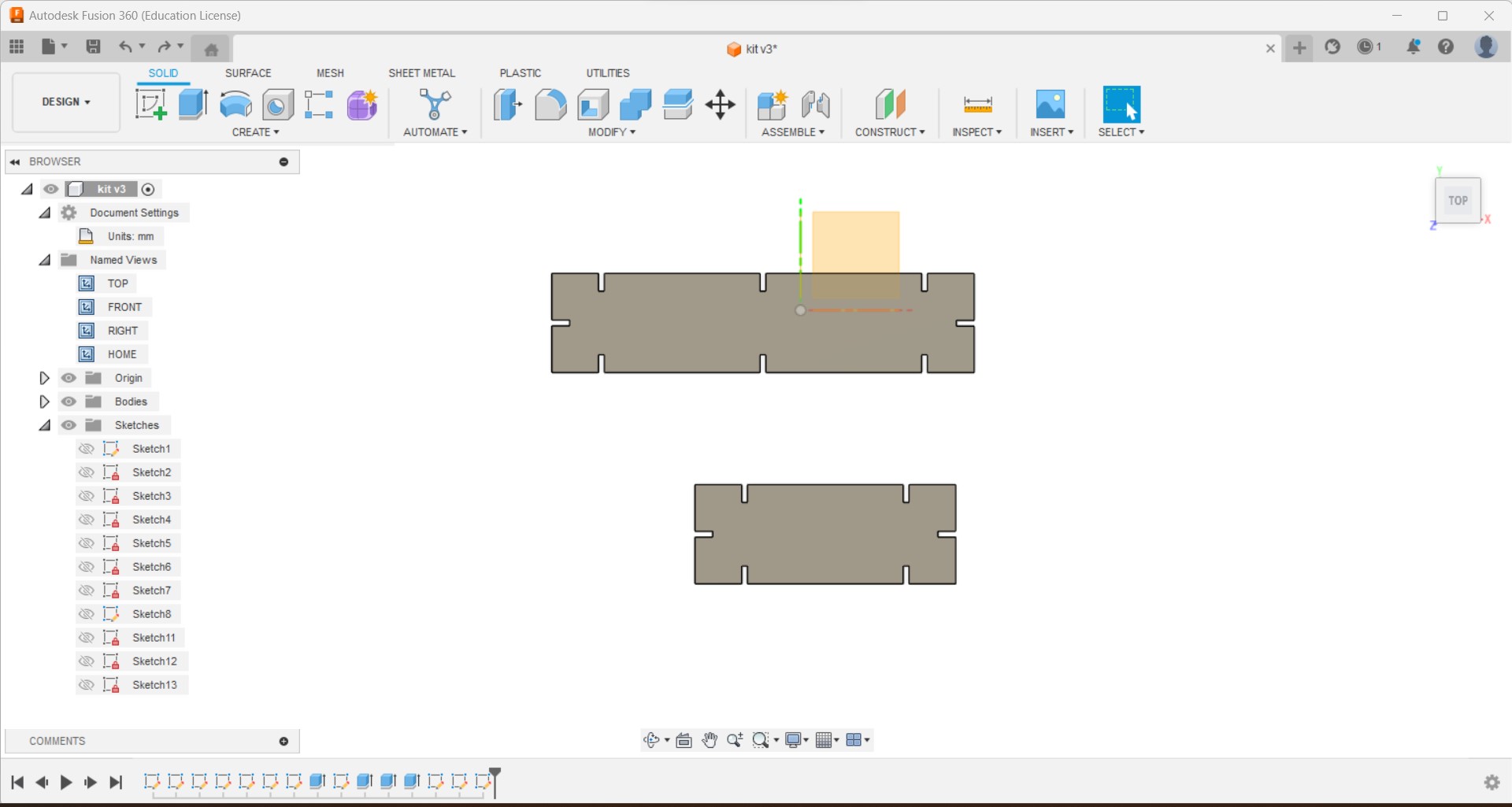
Complete the design
-
If I change a parameter, the design is changed accordingly.
Changig kerf parameter bigger (10mm)
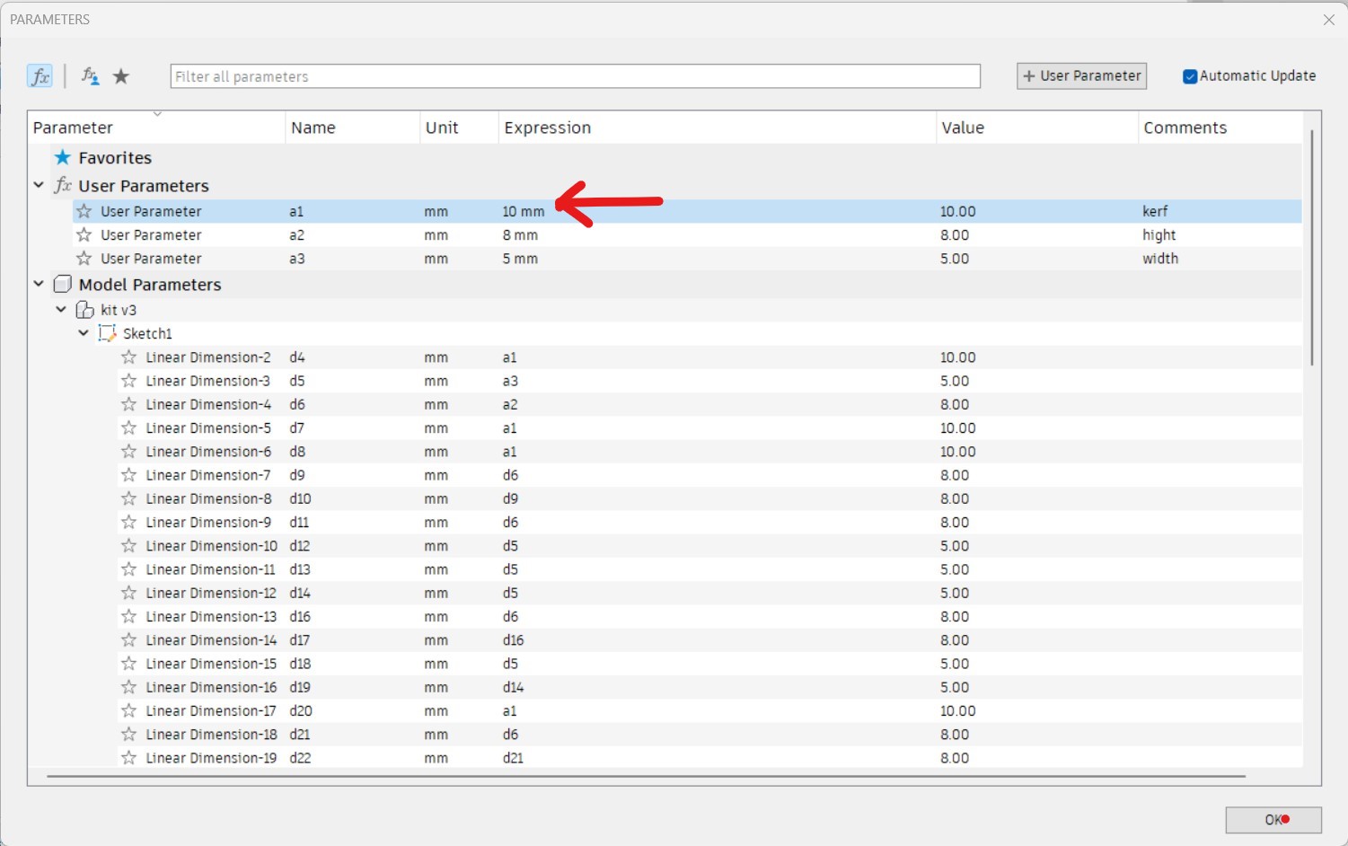
Then design shows 10mm kerf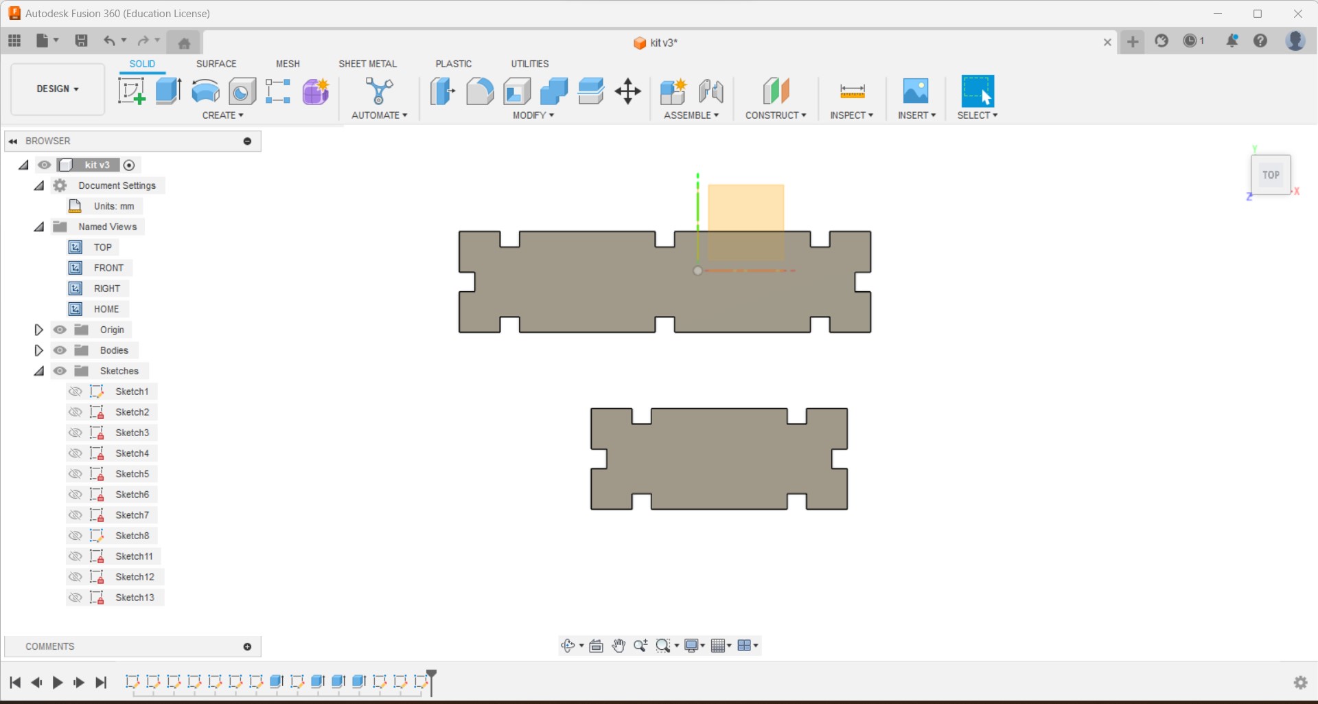
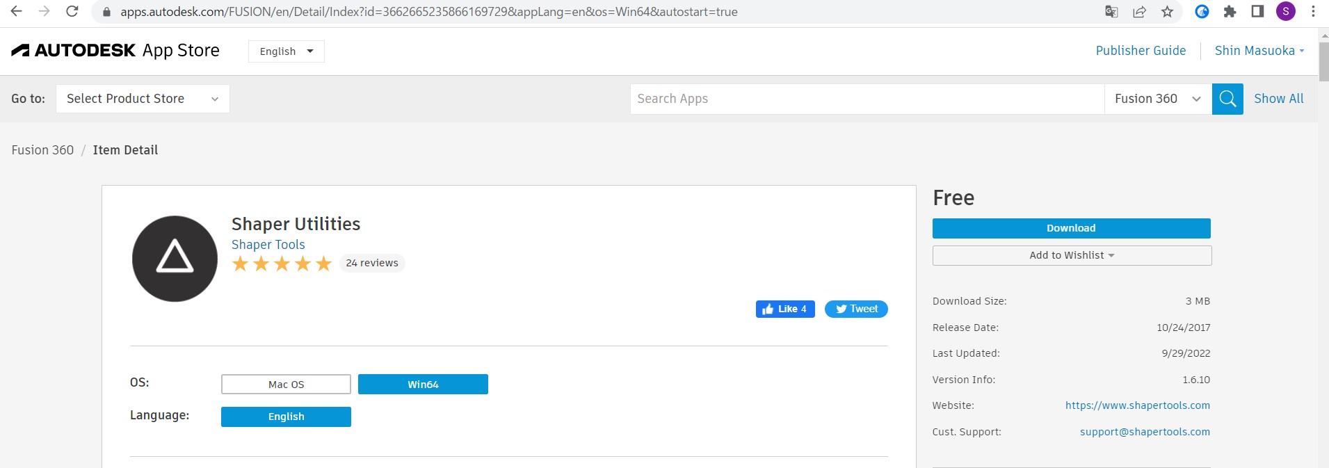
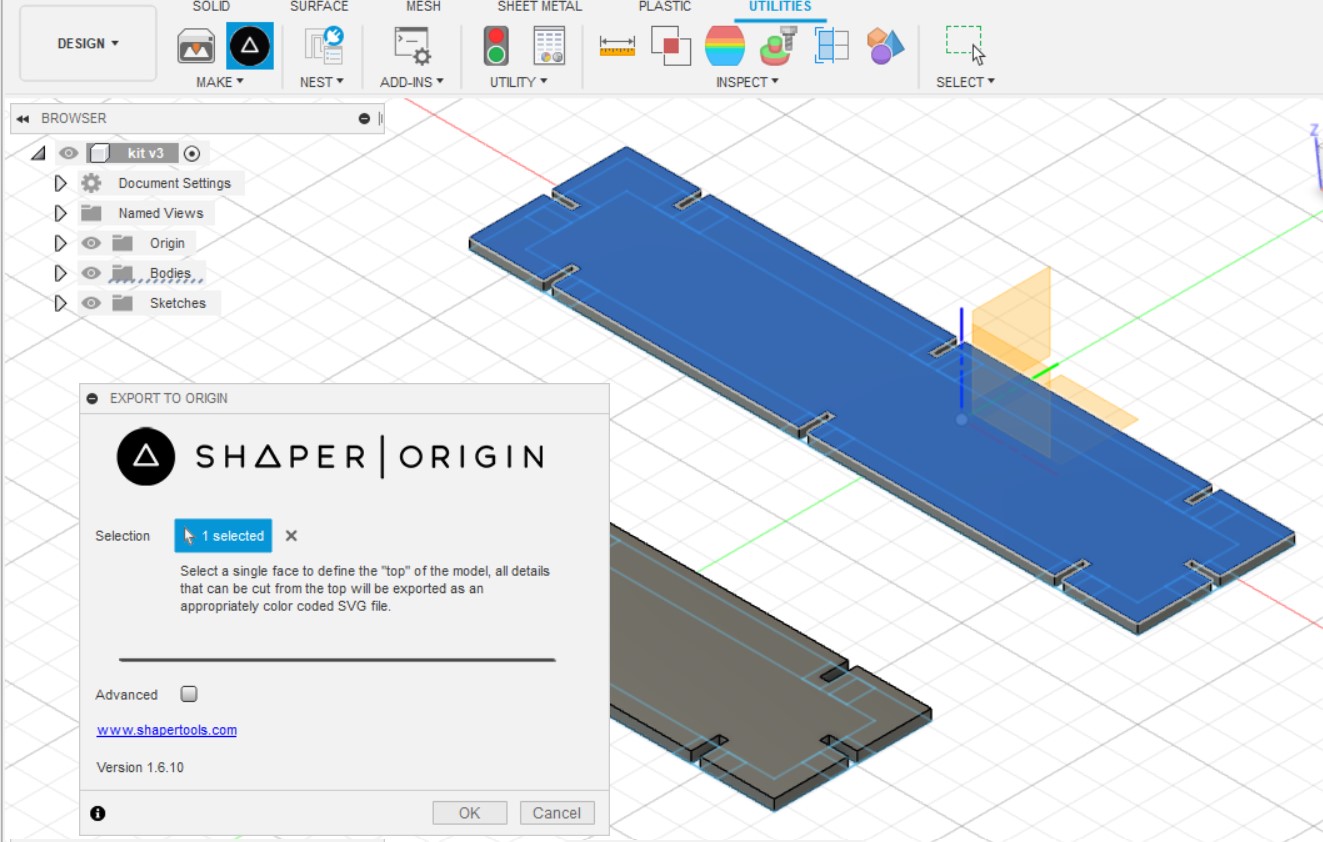
Making cutting data with "Shaper utilities"
Our instructor introduced add-in for fusion "shaper utilities". Which copies one face of the 3D shapes in fusion360.
-
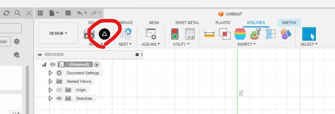
Installed the add-in, the add-in is shown in "make panel"
-
I made parametric design of the kit with fusion360. (original file)
- From the result of group work, kerf width should be 0.2 mm for 3mm thick cardboard.
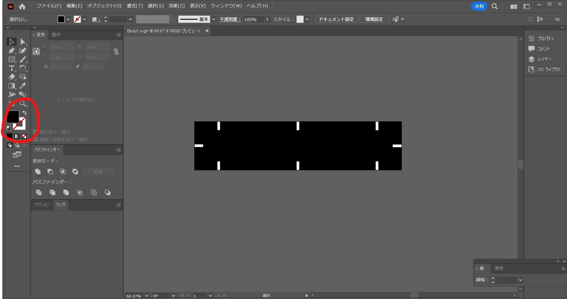
- Copied top face into svg file.
- Remove filling in and leave only outline for laser cutting.(original data)
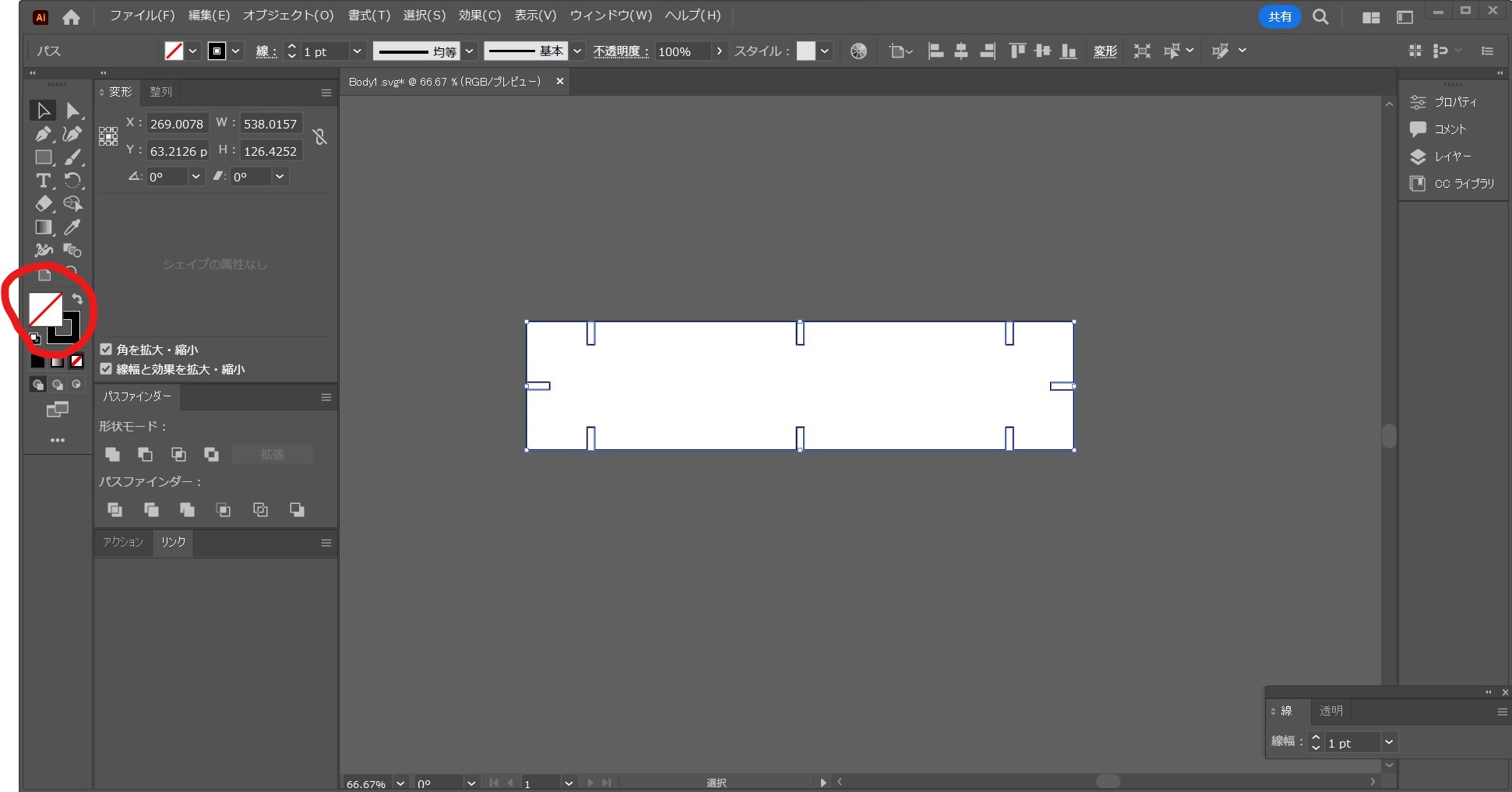
6. Import the data into laser cutter control software(Smart DIYs Creator)
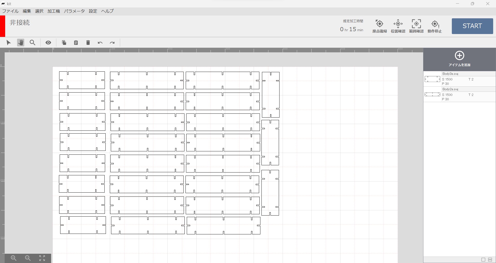
- Cutting with our laser cutter.
e2-2) Thoughts and feelings
- I had no idea to change fusion360 data for cutting. The data conversion tool or method is very important.
- Parametric designing is quite important and constraints as well. Our instructor pointed my data out that I used too much dimension settings, it made my data congested in appearance. If I used constraints, it should be simpler. I noted this and tried to the same drawing with constraints. Obviously it is faster and simpler.
- To make repeated design or symmetry design, this time slots, "Pattern" and "Mirror" function are useful.
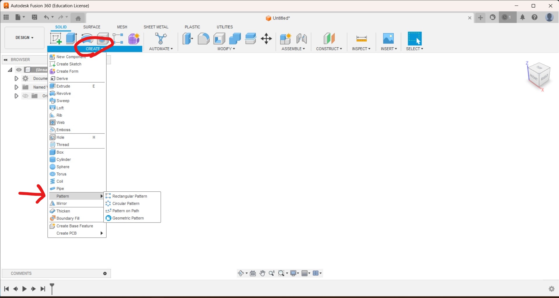
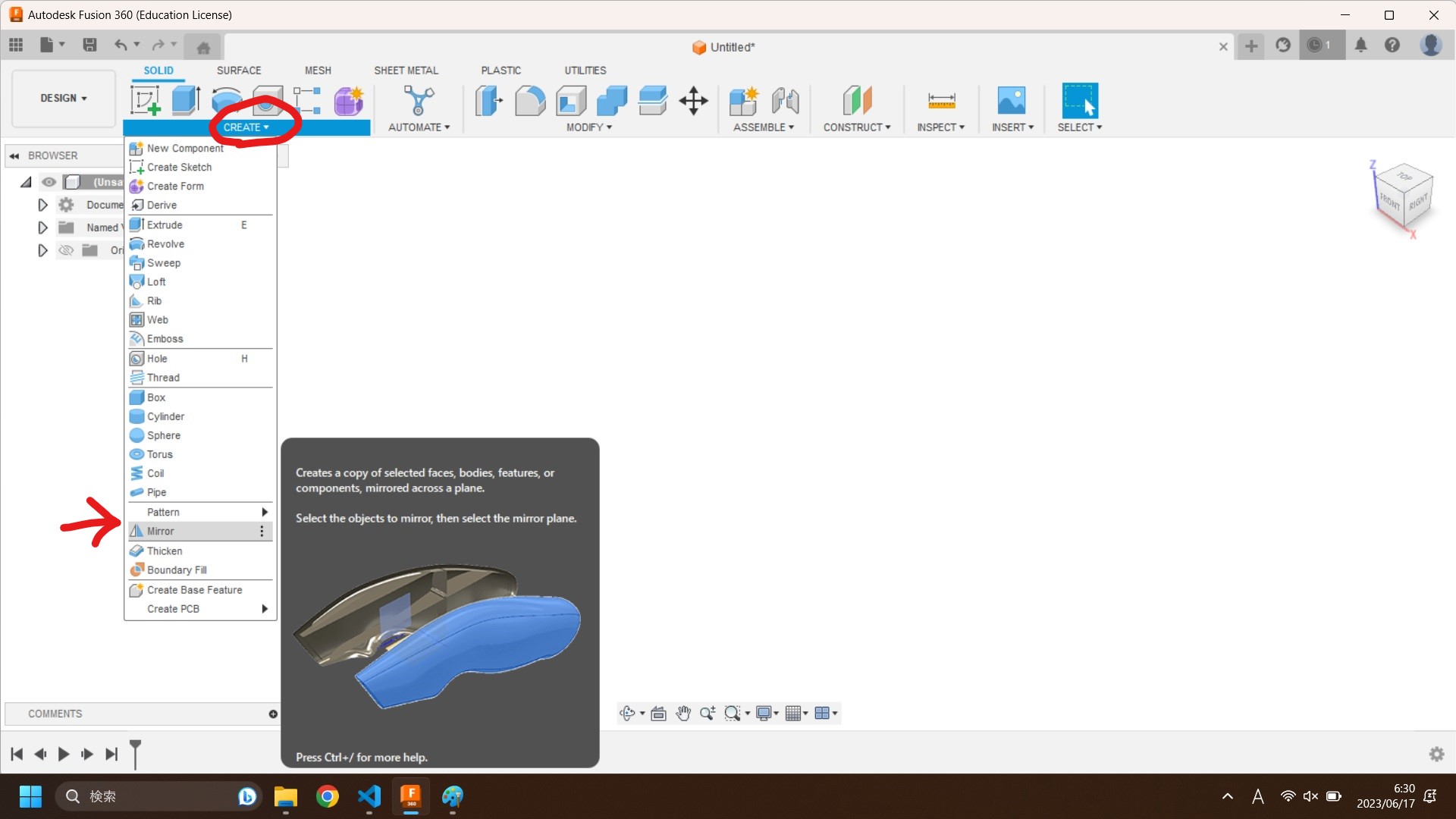
But this time I did not know use it. As a result the design appearance is complicated even such a simple design. I should study and use many functions to make the work simple.
end of the document