Final Project
For this project, I keep CC BY.
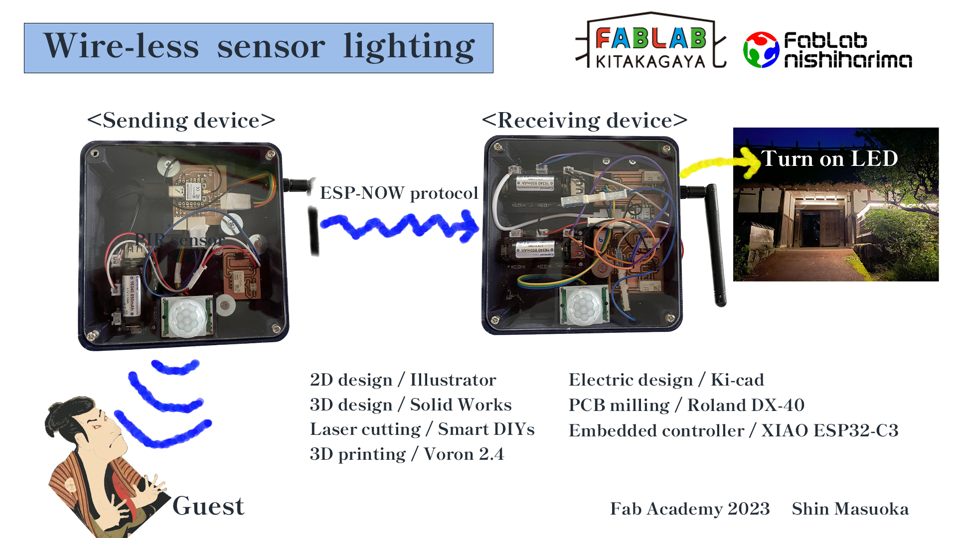
Wire-less sensor lighting system
In week 13 group assignment, I learnt wireless communication with Esp-now protocol. I was so amazed that I changed my mind for final project to utilize this wireless communication.
Summary Slide
One minute video
Background
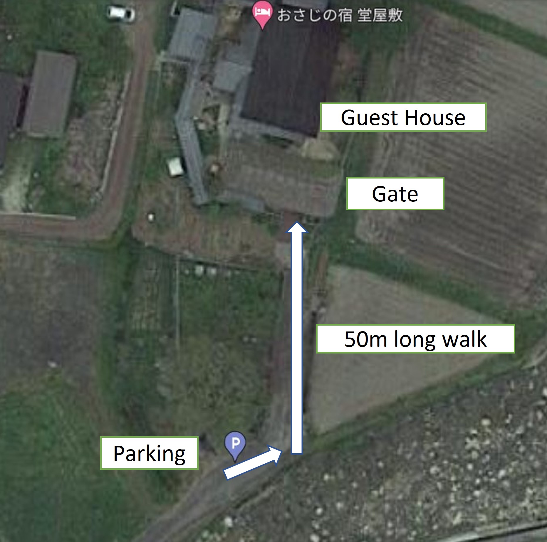
- I started running a guesthouse (tourist accommodation)
- Our guest house is in a mountain village. No lighting along the road
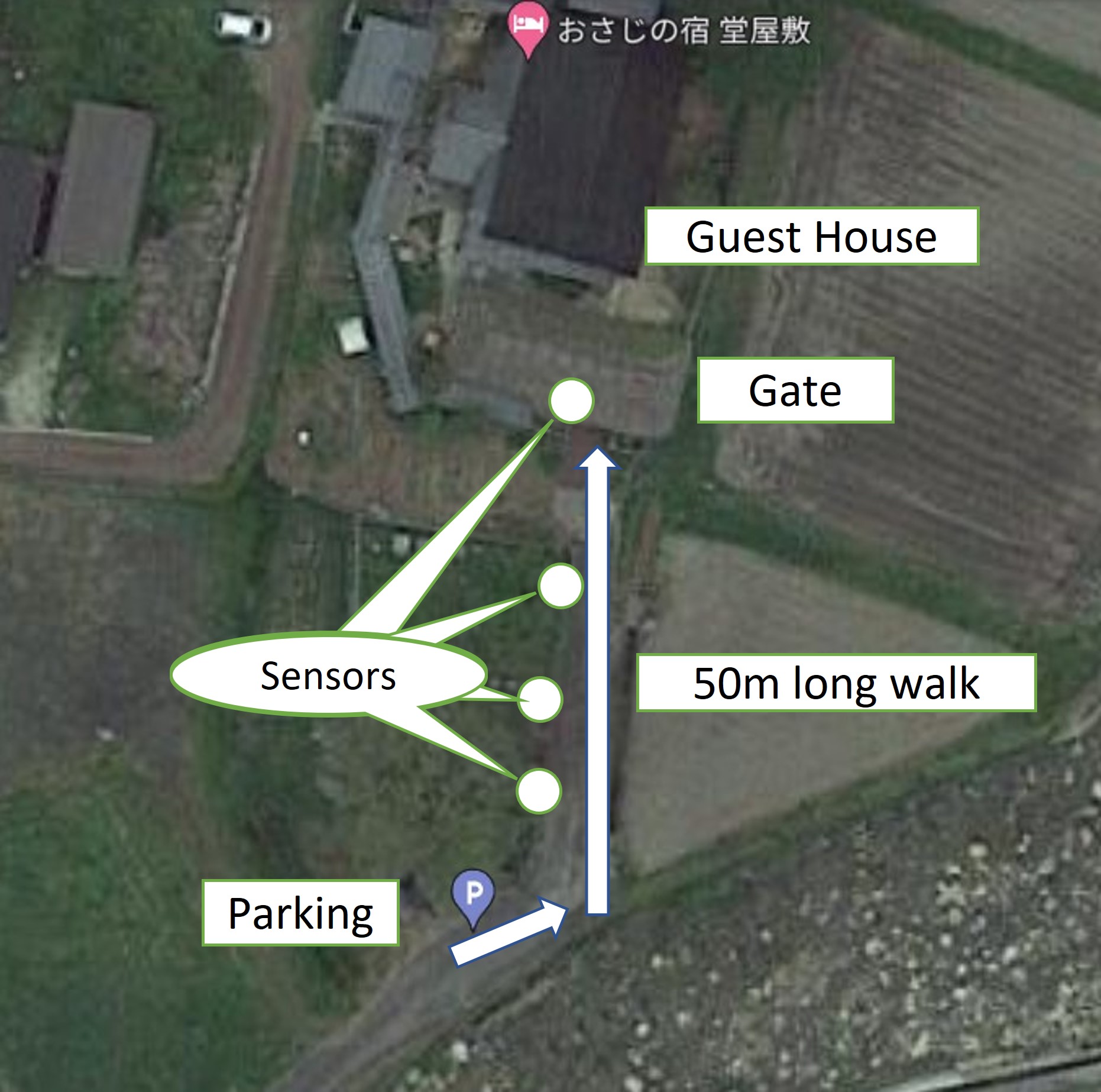
- Guests need to walk approx. 50m in the dark.
-
Our guesthouse has a nice old gate, I want to light up this to show nicely and a kind of light house when it is dark.
-
Lighting gradually turned on along guests approaching.
-
Some sensors detect guest approaching and the signal sent to mother board wire-less-ly.
-
The lighting color and pattern can be arranged by programming.
Making process
1 System design
- Use Esp-now protocol for communication between "Sender" and "Receiver"
- Make 2 "Sender"s (Esp-now allows up to 20 devices communication)
- Use PIR sensor to detect guests approaching
- Use 5V Li-po battery
- Use 5V relay to turn on/off LED, the reason why I use 5V one is that I could not find SMD relay with lower working voltage.
- Use photo coupler to use 5V relay
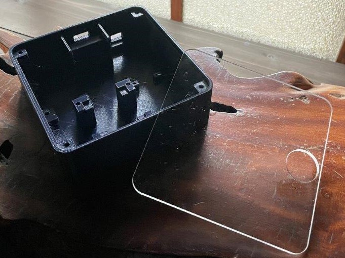
2 Casing
- Design of casing learned in week 2
3D (Solid Works original data)
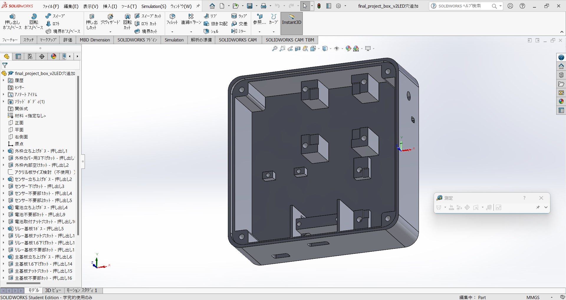
2D (Illustrator original data)
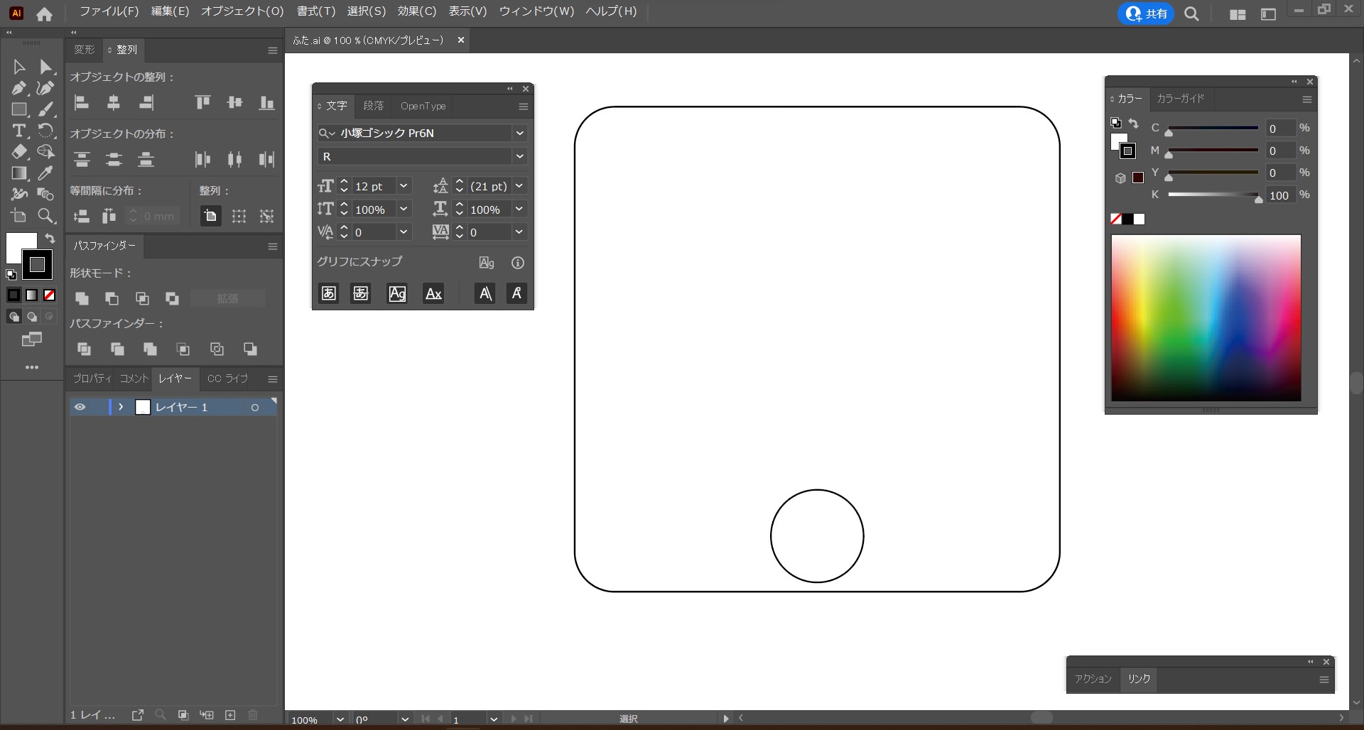
-
Laser cutting with Smart DIYs FABOOL CO2 learned in week 3
3 Electronics production
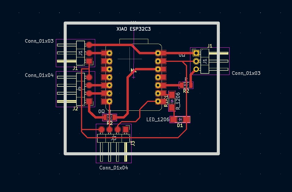
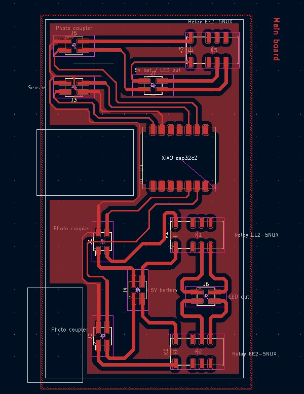
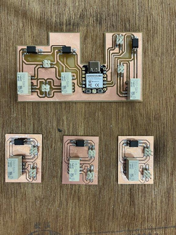
- Design of boards learned in week 6
Sender board (Ki-cad original file)
Receiver board (Ki-cad original file)
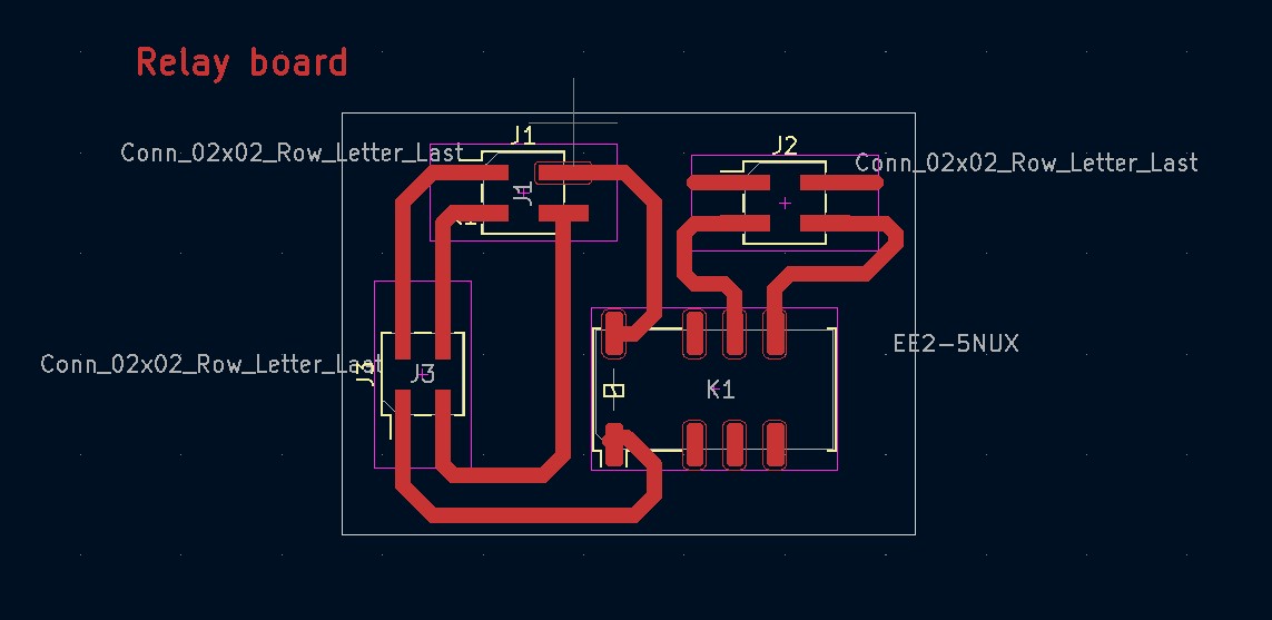
Relay board (this is not used in the end) (Ki-cad original file)
This time, I used 5V relay to turn on LEDs with 2 reasons.
1. I wanted to use relay for future prototyping
2. For Fab Academy, SMD device is required and I looked for SMD relay, and I only found 5V SMD relay, of course there were lower voltage relay but not SMD type.
As a result I used a mix of photo coupler and the relay because output from the chip's digital pins are under 5V not enough for the relays, there is only 1 pin which supplies 5V but not recommendable to connect several devices to the 5V pin. So I used 5v battery to open/close the relays, photo couplers work as gates from battery to relay.
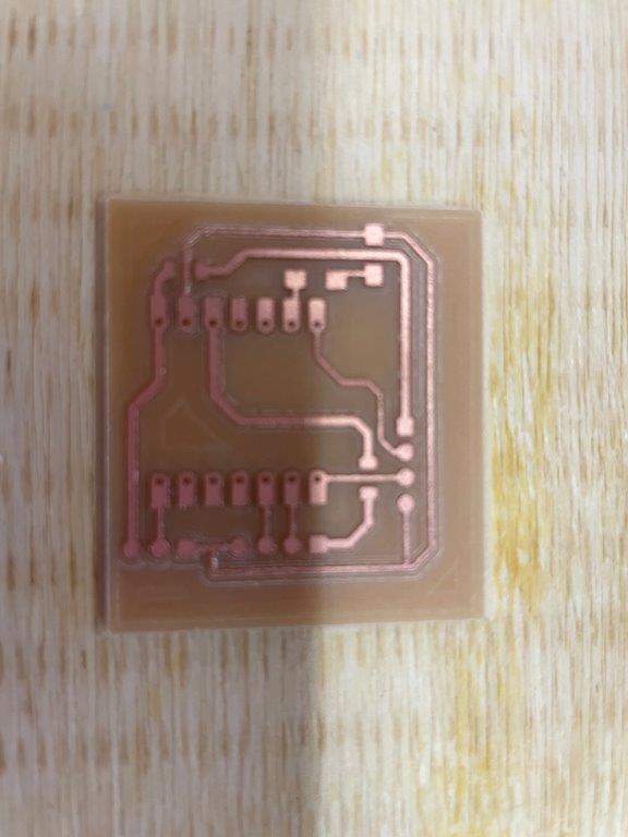
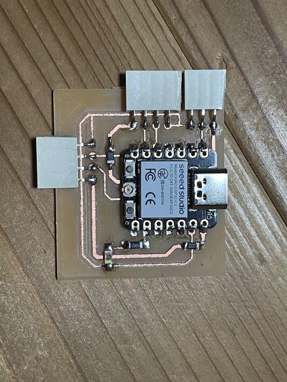
- Making boards learned in week 8
Sender board milling done
Sender board soldering done
Receiver board milling done
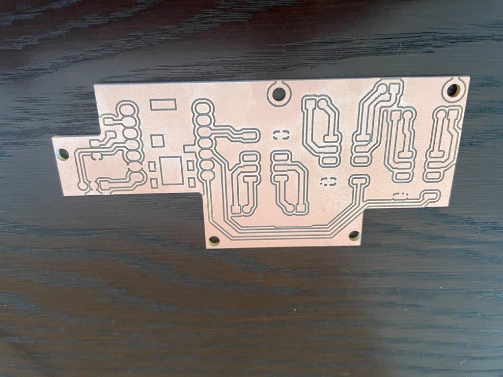
Receiver board soldering done
- Programming with ESP-NOW learned in week 13
Sender
// Shin Masuoka,Fab Academy 2023
// Sender code for Final project
// CC BY
// XIAO ESP32C3

#include <Arduino.h>
#include <WiFi.h>
#include <esp_now.h>

const int sensorPin = 21; // Define sensor pin

// MAC address of Receiver board
uint8_t board4Address[6] = {0x68, 0x67, 0x25, 0xEE, 0xA7, 0xB8};

// Sending data structure
typedef struct struct_message {
  int boardID;
  bool sensorState;
} struct_message;

struct_message myData;

// Indicate sending data successful or failure
void OnDataSent(const uint8_t *mac_addr, esp_now_send_status_t status) {
  Serial.print("Last Packet Send Status: ");
  if (status == ESP_NOW_SEND_SUCCESS) {
    Serial.println("Delivery success");
  } else {
    Serial.println("Delivery fail");
  }
}

void setup() {
  Serial.begin(115200);
  pinMode(sensorPin, INPUT); // Sensor pin setting

  myData.boardID = 1; // ID of this bord to identify at Receiver side

  WiFi.mode(WIFI_STA); // Set Wi-Fi station mode
  WiFi.disconnect(); // Disconnect if any other Wi-Fi connection

  // Initialize ESP-NOW
  if (esp_now_init() != ESP_OK) {
    Serial.println("ESP-Now Init Not Success");
    return;
  }

  // Setting for paring with Receiver board
  esp_now_peer_info_t peerInfo;
  memcpy(peerInfo.peer_addr, board4Address, 6);
  peerInfo.channel = 0;
  peerInfo.encrypt = false;

  // Show worning if peering failed
  if (esp_now_add_peer(&peerInfo) != ESP_OK) {
    Serial.println("Failed to add peer");
    return;
  }
 // Set a call back function on sent the signal
  esp_now_register_send_cb(OnDataSent);
}

void loop() {
  myData.sensorState = digitalRead(sensorPin); // Read the sensor status
  if (myData.sensorState == HIGH) { // When it is HIGH
        // Send the data to Receiver
    esp_now_send(board4Address, (uint8_t *)&myData, sizeof(myData));
  }
  delay(1000);
}
// Shin Masuoka,Fab Academy 2023
// Receiver code for Final project
// CC BY
// XIAO ESP32C3
#include <Arduino.h>
#include <WiFi.h>
#include <esp_now.h>

const int ledPin1 = 6; // LED pin settings for each Sender
const int ledPin2 = 7;
const int sensorPin = 9; // Sensor pin setting

// Define receiving data structure
typedef struct struct_message {
  int boardID;
  bool sensorState;
} struct_message;

struct_message incomingData;

// Define a call back function on receiving data
void OnDataRecv(const uint8_t *mac_addr, const uint8_t *data, int len) {
  memcpy(&incomingData, data, sizeof(incomingData));

  // Turn on LEDs depends on receiving data
  if (incomingData.sensorState == HIGH) {
    switch (incomingData.boardID) {
      case 1:
        digitalWrite(ledPin1, HIGH);

        break;
      case 2:
        digitalWrite(ledPin2, HIGH);

        break;
      case 3:
        digitalWrite(ledPin3, HIGH);
        break;
    }
  }
}

// Define a function which turns off all LED.
void turnOffLeds() {
  digitalWrite(ledPin1, LOW);
  digitalWrite(ledPin2, LOW);
}

void setup() {
  Serial.begin(115200);
  pinMode(ledPin1, OUTPUT); // LED pin settings
  pinMode(ledPin2, OUTPUT);
  pinMode(sensorPin, INPUT);

  WiFi.mode(WIFI_STA);
  WiFi.disconnect();


  if (esp_now_init() != ESP_OK) {
    Serial.println("Error initializing ESP-NOW");
    return;
  }


  esp_now_register_recv_cb(OnDataRecv);
}

void loop() {
  if (digitalRead(sensorPin) == HIGH) { // if sensor detect something
    delay(10000);
    digitalWrite(ledPin1, LOW);

    delay(1000);
    digitalWrite(ledPin2, LOW);

    delay(300000);
    turnOffLeds(); // Turn off all LEDs in 5 minutes (300 seconds)
  }
}
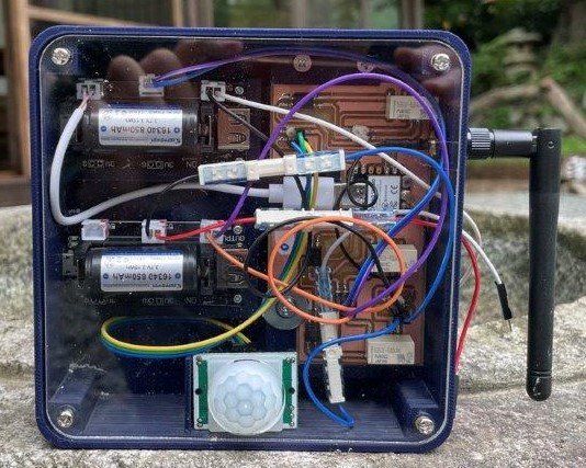
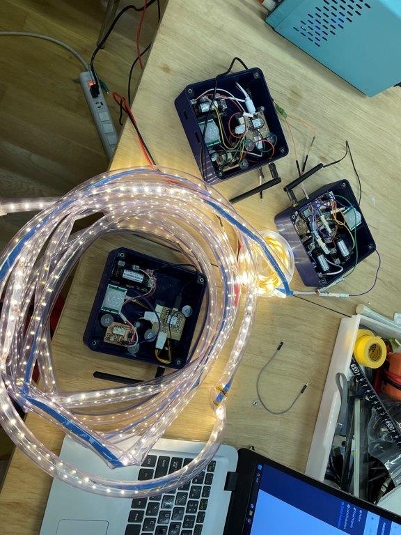
4 System integration
Sender device
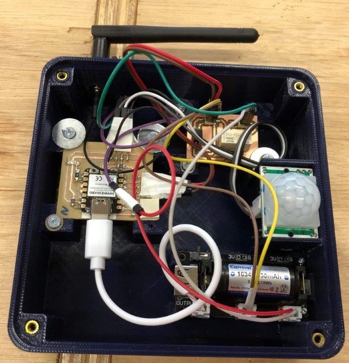
Receiver device
- At first my idea is put on LED for sender, too. The smaller board on sender is relay to turn on LED. But I decided not to use this board, because if each sender has LED, guest would not see the gate but sender's LED which is closer. It is against of my intention that this device is to make guest see or find the gate.
- It turned out one of my XIAO chip was not possible to access by USB serial for uploading codes. This is probably because the chip was heated 3 times for reflow by my poor soldering. So I decided to reduce number of sending device.
Questions to answer
What does it do ?
- This consist of 2 kind of devices, one is "Sender" and the other is "Receiver"
- "Sender" has a PIR sensor which detects guest approaching, and send signals to "Receiver" with ESP-NOW protocol. This system has 2 Senders.
- Once "Receiver" received the signal from Senders, it detects Sender's ID which is defined in the code of each Sender. Then turn on LEDs for each Sender which is defined in Receiver's code. Receiver also has a PIR sensor, once the PIR sensor detect something, it means someone arrived the gate, turn off LED in designated time passed.
Who's done what beforehand?
- I wanted wireless controlled lighting like Perttu Piirainen in 2019. But so far my skill is not such level. So this time just wire-less turn on and off.
What did you design?
-
I designed below
-
Case box (3D solid works)
-
Case cover (2D illustrator)
-
PCB (Kicad)
-
What materials and components were used?
Where did they come from?
How much did they cost?
- For those questions I made below table;
| Materials and components | units | unit price |
total JPY |
supplier |
|---|---|---|---|---|
| Battery | 5 | 995 | 4,975 | Yahoo shopping |
| xiao esp32c3 | 4 | 940 | 3,790 | Akizuki |
| 3D Printer filament | ? | ? | 2,000 | Lab inventory |
| LED tape | 5 | 330 | 1,650 | Daiso |
| Battery case | 5 | 200 | 1,000 | Lab inventory |
| acrylic board | 2 | 500 | 1,000 | Lab inventory |
| Antenna | 4 | 243 | 972 | Amazon |
| Sensor HC-SR501 | 4 | 180 | 720 | Amazon |
| Relay EE2-5NUX | 6 | 100 | 600 | Akizuki |
| Photocoupler TLP293 | 6 | 25 | 150 | Akizuki |
| USB type C cable | 4 | 50 | 200 | Seria |
| Others | 850 | Lab inventory |
In total JPY 17,907. (Approx. USD 125 @USD/JPY=143)
What parts and systems were made?
- Case box was made by 3D printing.
- Case cover was made by laser cutting.
- PCB was designed with Kicad and milled by Roland DX-40.
- Program was supported by Chat GPT
What processes were used?
- 2D/3D designing on my PC
- 3D printing as additive fabrication
- Laser cutting
- CNC PCB milling as subtractive fabrication
What questions were answered?
- Is 5V battery sufficient for this system -- it was sufficient, but for more LEDs I need to think about using AC.
- How I can develop this? More lighting, lighting pattern and so on -- not answered as final presentation.
- How far Esp-now can send signal in my case? -- For this system the signals were sent enough distance. I tested from 20m and 30m away without wall in between and it worked,
- How I can avoid unnecessary lighting like animals falling leaves? -- not answered as final presentation.
What worked? What didn't?
- This worked successfully. Each "sender" detect a person and turn on LED on "receiver" board respectively.
How was it evaluated?
- I will actually set it for my guest house, our guest might comment on our Airbnb site
- At least I am very happy with the test result.
What are the implications?
- At first, in day time I set "Sender"s near the gate and tested. It worked as expected.
- Next, in the evening I set "Sender"s approx. 20m and 30m away from the gate and it worked.
Power Budget
-
I measured power consumption of receiver board at; a) All LEDs on, all relay and sensor working
b) Only controller working (stand by)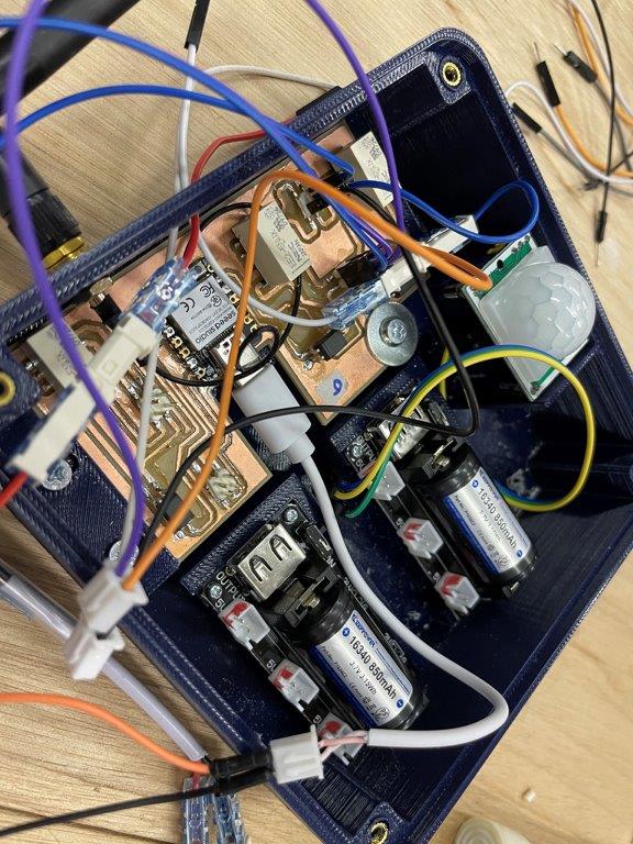
-
As a result:
a) 6.16w (4.93V, 1.248A)
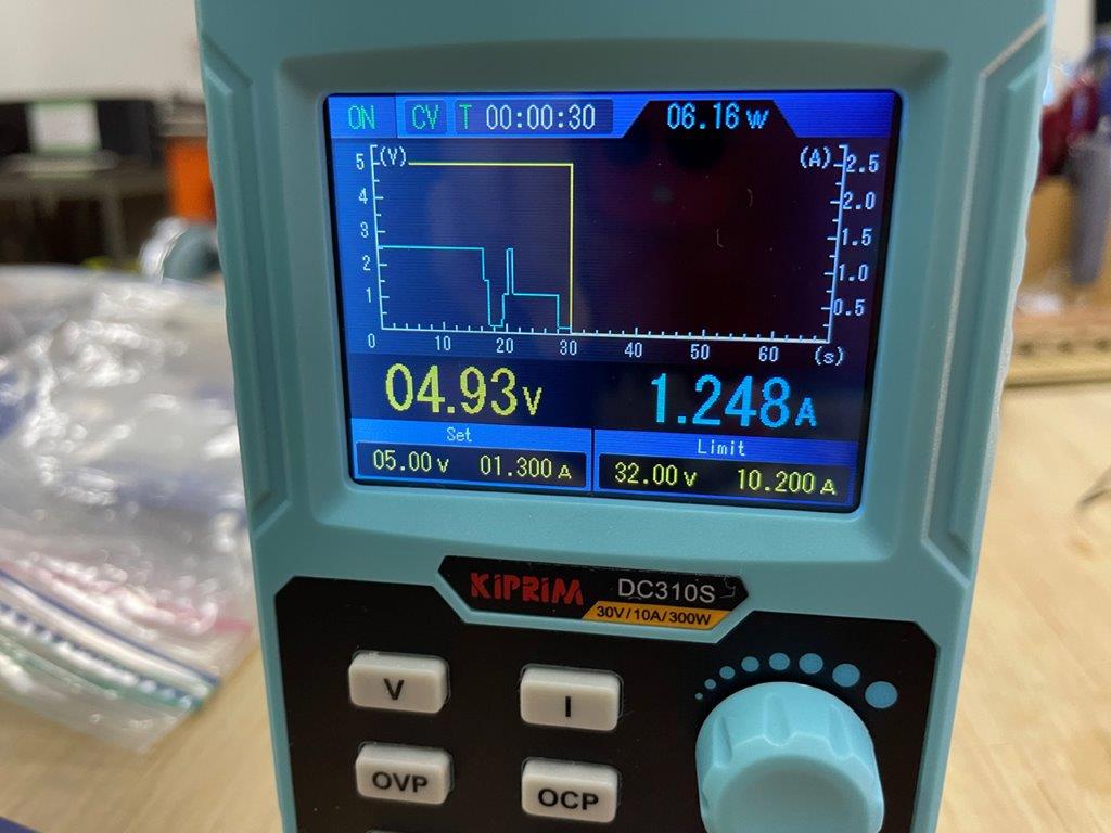
b) 0.35W (4.94V, 0.07A)
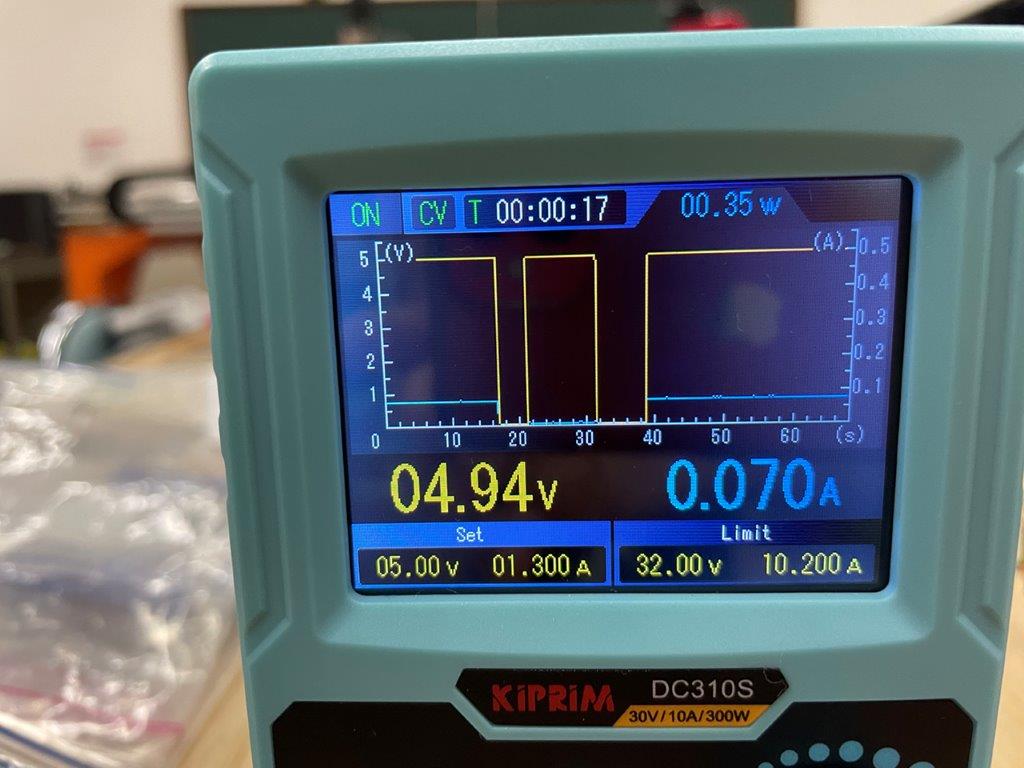
I am using 5V li-po battery with 16340 Mobile power battery holder module
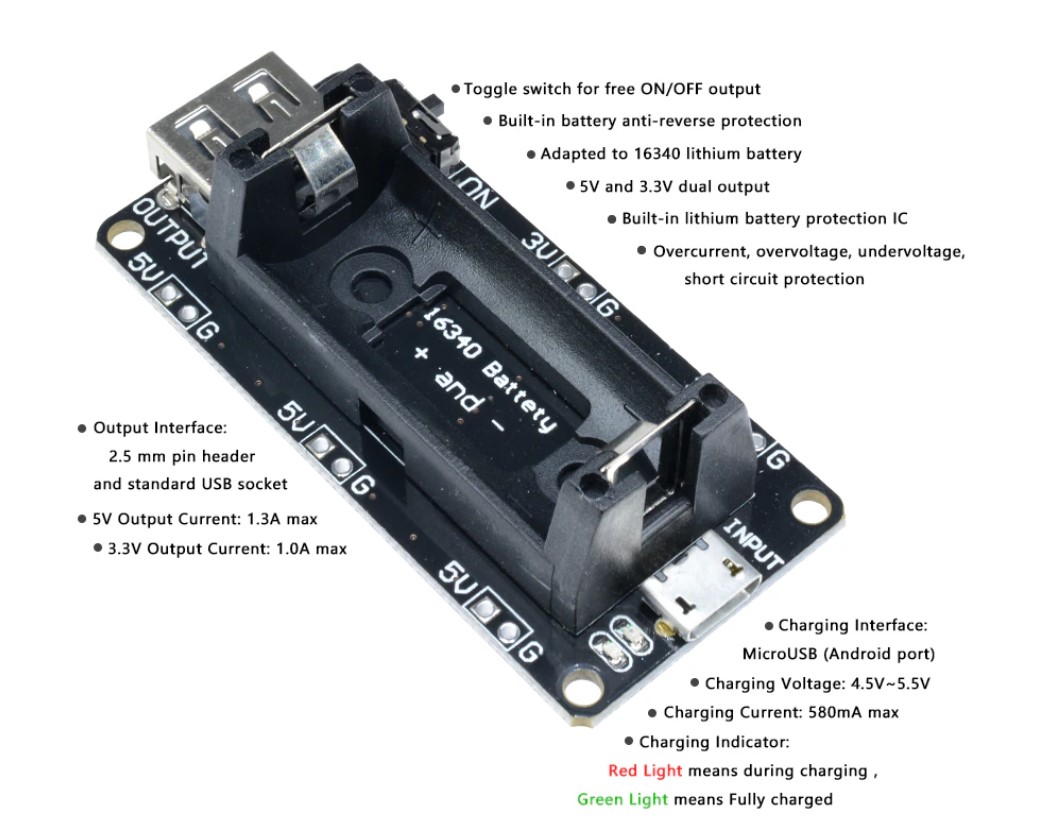
This shows "5V output current: 1.3A max"
It means the max power consumption of receiver board is almost limit of the battery holder module. In theory one 5V li-po battery possible to run the board, but for keeping margin I use 2 batteries. One battery powers one LED and one relay and the other powers one LED, one relay and one controller
(end of document)