Week 18 Project development
what tasks have been completed?
As of 31 May 2023, I have completed;
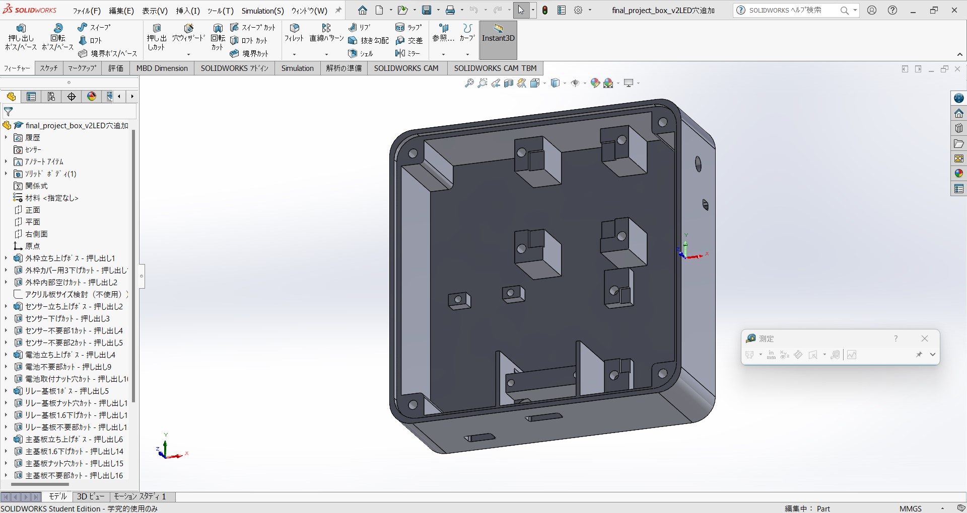
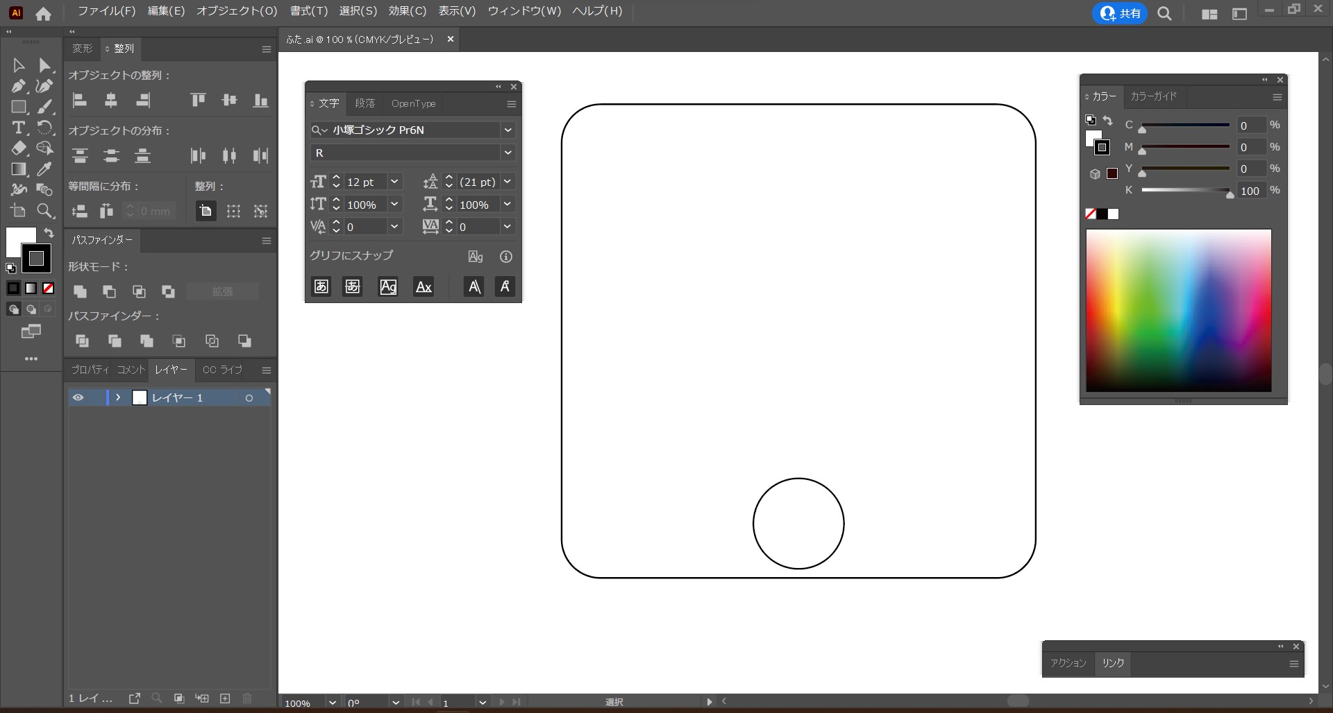
- Design of casing
-
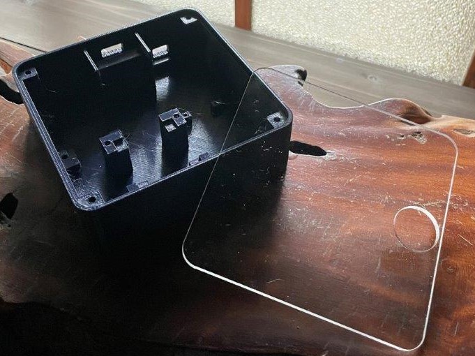
3D print and laser cutting of casing
-
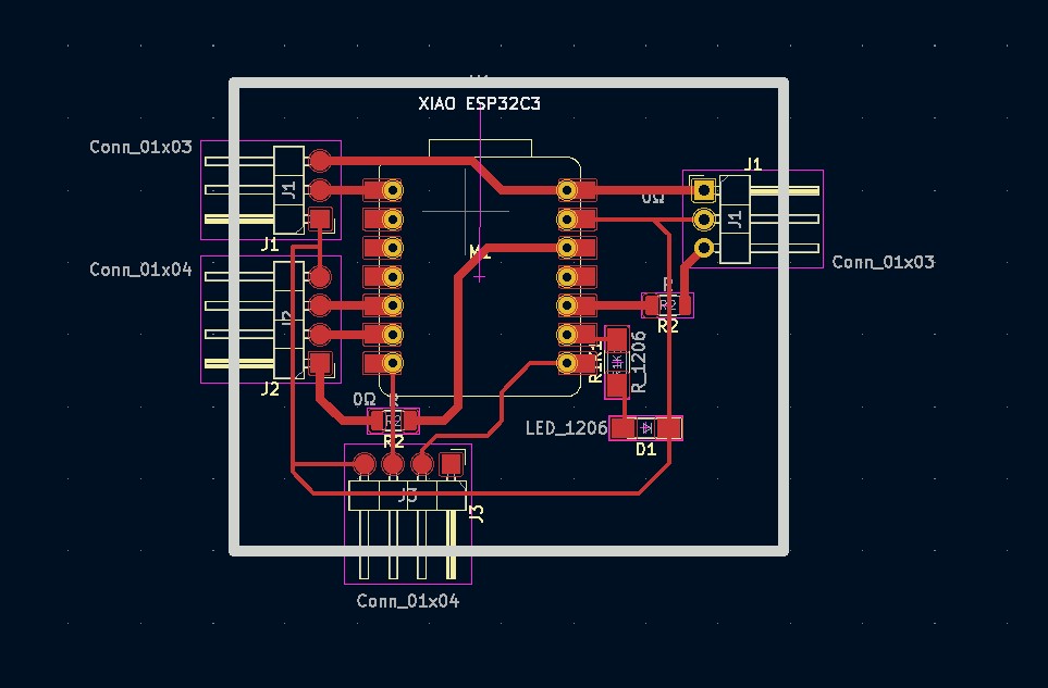
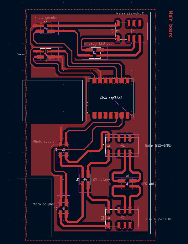
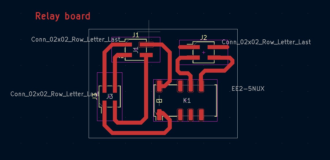
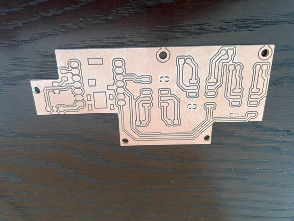
Design of boards
-
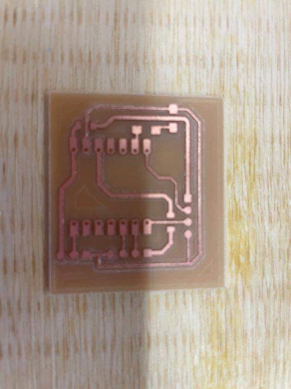
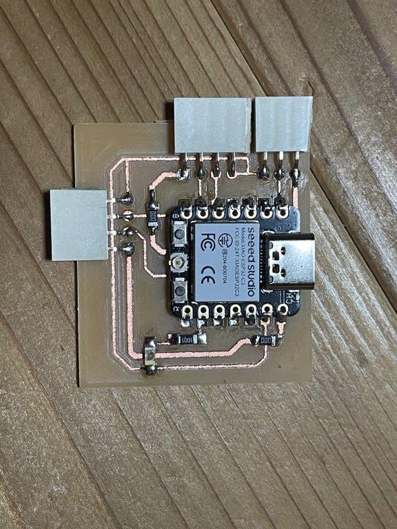
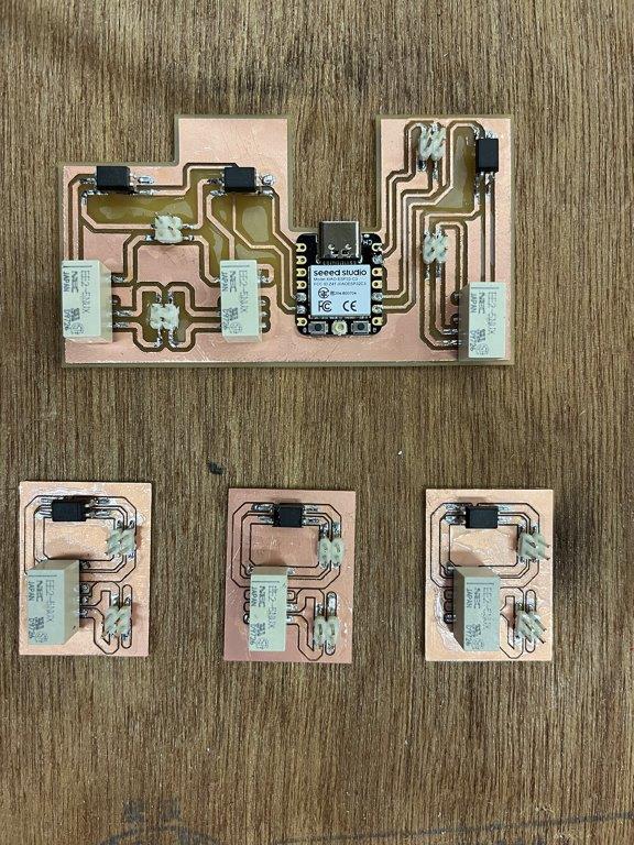
Making boards
-
Programming for test The code is at end of the document.
-
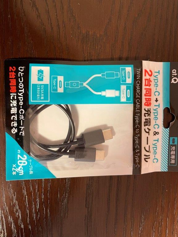
Purchase other parts
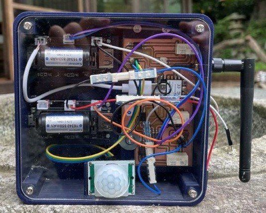
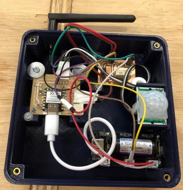
- System integration
what tasks remain?
- By the presentation on 14 June 2023, remaining tasks are;
- System integration
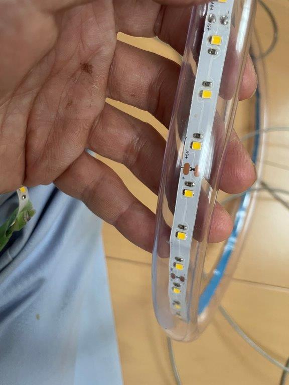
- LED setting of the gate
- Test the code work on actual device
- Debugging one board which is not accessible via Arduino IDE for code uploading.
- Making slide and video clip
what has worked? what hasn’t?
- ESP-NOW worked, I tested communication 5m distance.
- A relay on receiver board did not work, because I soldered a photocoupler wrong way.
what questions need to be resolved?
- Sometimes the devices do not communicate after turning on. And sometimes work. What is the precise procedure for activating the devices?
- Do I need to put LED for each sending device? It seems not necessary for better visibility of the main lighting.
- Does it work under rainy or snowy condition?
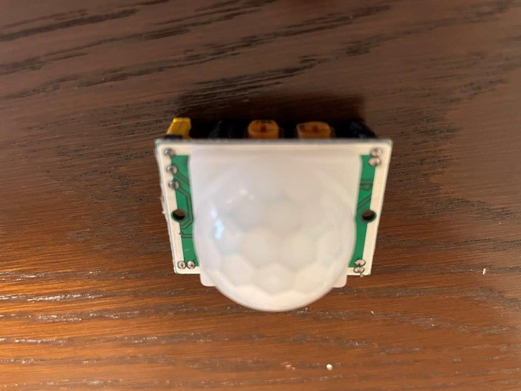
- Neil recommended doppler radar instead of PIR sensor, which is better?
what will happen when?
- System integration, complete build up devices by 5th June
- Making decision for below by 5th June
- Put LED on sender device
- Find the cause of not accessible device
- Repair or not mis-soldered photocoupler
- Test with actual place, LEDs on 6th June
- Debugging if any by 12th June
- Complete the slide by 12th June
- Complete the video clip by 12th June
what have you learned?
- ESP-NOW protocol
- Difficulty of physical system integration like keeping space of cables, easy access to bolt and battery switches.
- Toughness of cables and cables connection is important, otherwise it is easily broken during test many times.
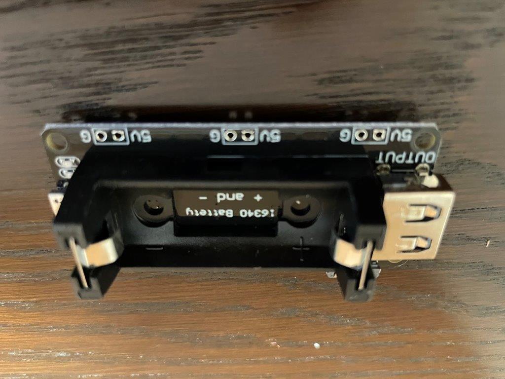
- How to handle li-po battery.
- How to use photocoupler, relay and PIR sensor
- Precise soldering with flux (I was not using flux)
- Debugging with micrometer especially soldering check
Codes for test
Sender
#include <Arduino.h>
#include <WiFi.h>
#include <esp_now.h>

const int sensorPin = 21; // Define sensor pin
const int ledPin = 7; // Define LED pin

// MAC address of Receiver board
uint8_t board4Address[6] = {0x68, 0x67, 0x25, 0xEE, 0xA7, 0xB8};

// Sending data structure
typedef struct struct_message {
  int boardID;
  bool sensorState;
} struct_message;

struct_message myData;

// Indicate sending data successful or failure
void OnDataSent(const uint8_t *mac_addr, esp_now_send_status_t status) {
  Serial.print("Last Packet Send Status: ");
  if (status == ESP_NOW_SEND_SUCCESS) {
    Serial.println("Delivery success");
  } else {
    Serial.println("Delivery fail");
  }
}

void setup() {
  Serial.begin(115200);
  pinMode(sensorPin, INPUT); // Sensor pin setting
  pinMode(ledPin, OUTPUT); // LED pin setting

  myData.boardID = 1; // ID of this bord to identify at Receiver side

  WiFi.mode(WIFI_STA); // Set Wi-Fi station mode
  WiFi.disconnect(); // Disconnect if any other Wi-Fi connection

  // Initialize ESP-NOW
  if (esp_now_init() != ESP_OK) {
    Serial.println("ESP-Now Init Not Success");
    return;
  }


  // Setting for paring with Receiver board
  esp_now_peer_info_t peerInfo;
  memcpy(peerInfo.peer_addr, board4Address, 6);
  peerInfo.channel = 0;
  peerInfo.encrypt = false;

  // Show worning if peering failed
  if (esp_now_add_peer(&peerInfo) != ESP_OK) {
    Serial.println("Failed to add peer");
    return;
  }
 // Set a call back function on sent the signal
  esp_now_register_send_cb(OnDataSent);
}

void loop() {
  myData.sensorState = digitalRead(sensorPin); // Read the sensor status
  if (myData.sensorState == HIGH) { // When it is HIGH
    digitalWrite(ledPin, HIGH); // Tun on the LED
    delay(1000);
    digitalWrite(ledPin, LOW);// Turn off the LED after a second
    // Send the data to Receiver
    esp_now_send(board4Address, (uint8_t *)&myData, sizeof(myData));
  }
  delay(1000);
}
Receiver
#include <Arduino.h>
#include <WiFi.h>
#include <esp_now.h>

const int ledPin1 = 6; // LED pin settings
const int ledPin2 = 7;
const int ledPin3 = 8;
const int sensorPin = 9; // Sensor pin setting

// Define receiving data structure
typedef struct struct_message {
  int boardID;
  bool sensorState;
} struct_message;

struct_message incomingData;

// Define a call back function on receiving data
void OnDataRecv(const uint8_t *mac_addr, const uint8_t *data, int len) {
  memcpy(&incomingData, data, sizeof(incomingData));

  // Turn on LEDs depends on receiving data
  if (incomingData.sensorState == HIGH) {
    switch (incomingData.boardID) {
      case 1:
        digitalWrite(ledPin1, HIGH);

        break;
      case 2:
        digitalWrite(ledPin2, HIGH);

        break;
      case 3:
        digitalWrite(ledPin3, HIGH);
        break;
    }
  }
}

// Define a function which turns off all LED.
void turnOffLeds() {
  digitalWrite(ledPin1, LOW);
  digitalWrite(ledPin2, LOW);
  digitalWrite(ledPin3, LOW);
}

void setup() {
  Serial.begin(115200);
  pinMode(ledPin1, OUTPUT); // LED pin settings
  pinMode(ledPin2, OUTPUT);
  pinMode(ledPin3, OUTPUT);
  pinMode(sensorPin, INPUT);

  WiFi.mode(WIFI_STA);
  WiFi.disconnect();


  if (esp_now_init() != ESP_OK) {
    Serial.println("Error initializing ESP-NOW");
    return;
  }


  esp_now_register_recv_cb(OnDataRecv);
}

void loop() {
  if (digitalRead(sensorPin) == HIGH) { // if sensor detect something
    delay(10000);
    digitalWrite(ledPin1, LOW);

    delay(1000);
    digitalWrite(ledPin2, LOW);

    delay(1000);
    digitalWrite(ledPin3, LOW);

    delay(300000);
    turnOffLeds(); // Turn off all LEDs in 5 minutes (300 seconds)
  }
}