Week 14- Group / Interface and Application
This is group assignment page of Interface and Application Programming (Kitakagaya students):
- Shin Masuoka
- Hiroe Takeda
Group assignment
- compare as many tool options as possible
What we did
- TRY creating UI and UX with HTML, CSS, and JS (Hiroe Takeda)
- TRY Blink (We both tried. below is Takeda’s article)
- TRY Processing (Shin Masuoka)
1.TRY creating UI and UX with HTML, CSS, and JS
I tried controled 3 LED on ESP32 Dev Module, through the Browser.
- The Result
- IDE and Board I used
- IDE: Arduino IDE
-
Board: ESP32 Dev Module is a board with ESP-WROOM-32.
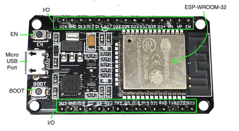
-
Boot: Download button.
- EN: Reset button
- I/O: Most of the pins on the ESP module are broken out to the pin headers on the board. You can program ESP32 to enable multiple functions such as PWM, ADC, DAC, I2C, I2S, SPI, etc.
Uplaod method by ESP32 Dev Module is special. When upload the code in Arduino IDE, hold down BOOT button and press EN button once, when the Upload’s percentage appear, unpush BOOT button.
- Main workflow
- Create HTML, CSS, JAVAsclipt files for browser, using Visual studio code.
- Install Arduino Libraries (ESPAsyncWebServer, AsyncTCP)
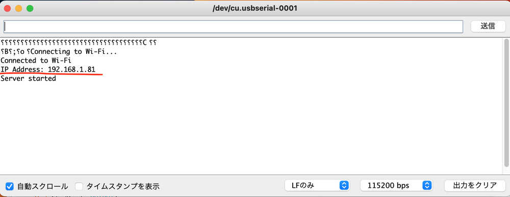
- Open Arduino IDE and Upload Arduino code, and open Serial monitor, and check ESP IP ADDRESS.
- Replace actual ESP32 IP address in JavaScript file.
- Open index.html in a browser and I could control the ESP32 LED.
NOTE:
- ESP32 and PC connect to the same Wi-Fi network.
- Generated code with ChatGPT (GPT-4).
Main instructions for ChatGPT (GPT-4)
- connect ESP32 to wifi and control the device from a browser.
- Please write a program to control 3 LEDs from a browser.
- I want to prepare HTML, CSS and JAVAscripts on the PC to control the device from the same wifi network. Please write HTML, CSS and JAVAsclipt for the browser.
The completed code is as follows.
- HTML
file name: index.html
I added a HEADER to add my own edits. (Line 11-12)
<!DOCTYPE html>
<html lang="en">
<head>
  <meta charset="UTF-8">
  <meta name="viewport" content="width=device-width, initial-scale=1.0">
  <title>ESP32 LED Control</title>
  <link rel="stylesheet" href="styles.css">
</head>
<body>
  <h1>ESP32 LED Control</h1>
  <h2>Hiroe's FabAcademy </h2>
  <h3>week14 Interface and Apprication Programming</h3>
  <div class="container">
    <div class="led" id="led1" onclick="toggleLed(1)">LED 1</div>
    <div class="led" id="led2" onclick="toggleLed(2)">LED 2</div>
    <div class="led" id="led3" onclick="toggleLed(3)">LED 3</div>
  </div>
  <script src="script.js"></script>
</body>
</html>
- CSS
file name: styles.css
body {
  font-family: Arial, sans-serif;
  text-align: center;
}

.container {
  display: flex;
  justify-content: center;
  flex-wrap: wrap;
}

.led {
  width: 100px;
  height: 100px;
  margin: 10px;
  border: 2px solid #ccc;
  border-radius: 50%;
  display: flex;
  justify-content: center;
  align-items: center;
  cursor: pointer;
}

.led.on {
  background-color: #f00;
  border-color: #f00;
}
- JavaScript
file name: script.js
NOTE: Replaces actual ESP32 IP address, Line 1. (-> The confirmation method is as follows)
const esp32Url = 'http://192.168.1.81/led';

function toggleLed(ledNum) {
  const ledElement = document.getElementById(`led${ledNum}`);
  ledElement.classList.toggle('on');
  const isOn = ledElement.classList.contains('on');
  const ledState = isOn ? 1 << (ledNum - 1) : 0;

  fetch(`${esp32Url}?state=${ledState}`)
    .then(response => response.text())
    .then(text => console.log(text))
    .catch(error => console.error(error));
}
- Code for Arduino IDE
- Board: ESP32 Dev Module
- Port: /dev/cu.usbserial-0001
#include <WiFi.h>
#include <ESPAsyncWebServer.h>

// Wi-Fi setting
const char* ssid = "your wifi id";
const char* password = "your wifi password";

// LED Pin setting
const int ledPin1 = 2;  // D2
const int ledPin2 = 4;  // D4
const int ledPin3 = 5;  // D5

AsyncWebServer server(80);

void setup() {
  // Start serial communication
  Serial.begin(115200);


  // Set LED pins to output mode
  pinMode(ledPin1, OUTPUT);
  pinMode(ledPin2, OUTPUT);
  pinMode(ledPin3, OUTPUT);

  // Wi-Fi connection
  WiFi.begin(ssid, password);
  while (WiFi.status() != WL_CONNECTED) {
    delay(1000);
    Serial.println("Connecting to Wi-Fi...");
  }
  Serial.println("Connected to Wi-Fi");
  Serial.print("IP Address: ");
  Serial.println(WiFi.localIP());

  // Set route for LED control
  server.on("/led", HTTP_GET, [](AsyncWebServerRequest *request) {
    String stateParam;
    int state = 0;

    if (request->hasParam("state")) {
      stateParam = request->getParam("state")->value();
      state = stateParam.toInt();
      Serial.print("Received LED state: ");
      Serial.println(state);
    }

    digitalWrite(ledPin1, (state & 0x01) ? HIGH : LOW);
    digitalWrite(ledPin2, (state & 0x02) ? HIGH : LOW);
    digitalWrite(ledPin3, (state & 0x04) ? HIGH : LOW);

    request->send(200, "text/plain", "OK");
  });

  // Start Server
  server.begin();
  Serial.println("Server started");
}

void loop() {
  // Do not type anything here.
}
- ESP IP ADDRESS
Upload Arduino code, and open Serial Monitor and check ESP IP ADDRESS, then, inserted it into the Javascript.
- Reference (Arduino Libraries’s compile error)
I got compile error, with installing in the Arduino IDE’s library management. Therefore, I reinstalled the libraries manually, as follows.
- Download the following library as a ZIP file from the Github repository
- Unzip the downloaded ZIP file
- Copy the extracted folder to the Arduino’s library folder (folder place’s example: ~/Documents/Arduino/libraries/). then, I change folder name “ESPAsyncWebServer” and “AsyncTCP”
- Restart Arduino IDE
The library is now correctly installed, and there is no compile error!
2. TRY Blynk
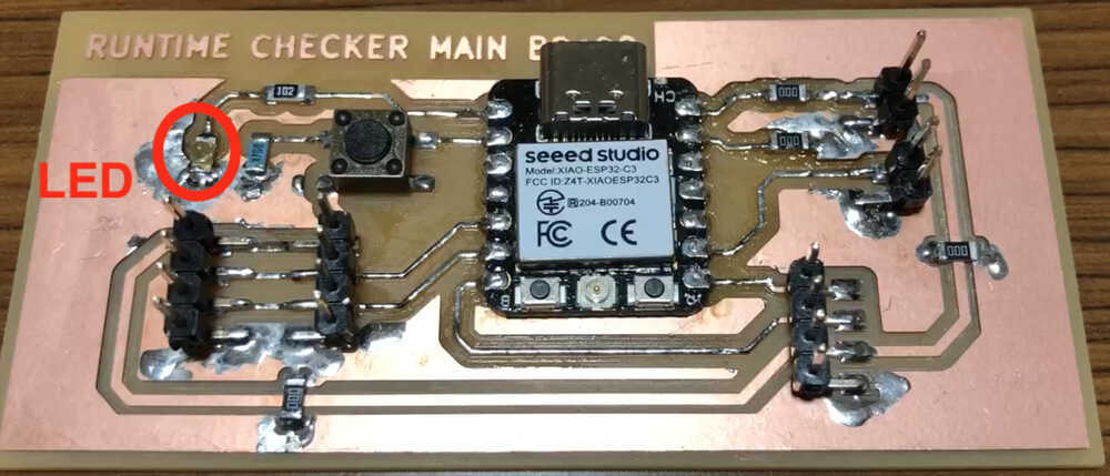
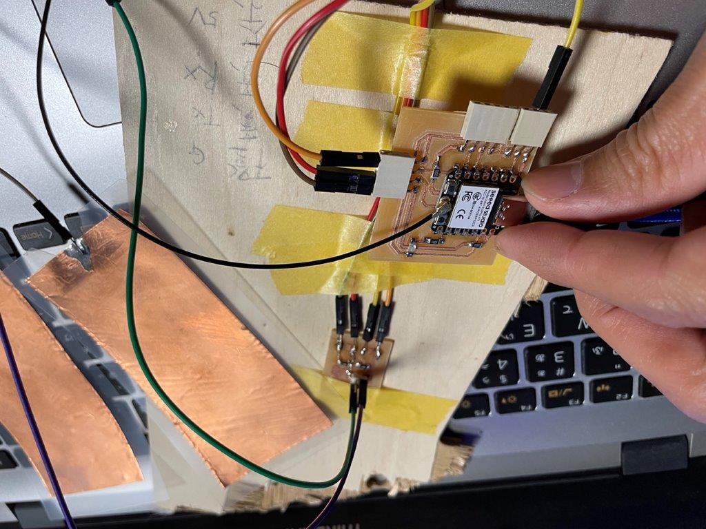
I tried control LED Pin 2 (GPIO pin 2) on ESP32 board that I designed by week09 with browser, using Blynk.

- The Result
As a result, I could control LED on/off with Blynk and PC Browser, and smartphone (4G).
I studied Blynk and watched youtube: hitunodsnpo (Japanese), then start it.
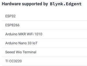
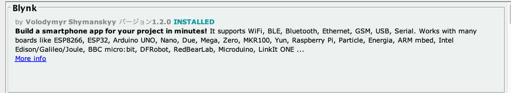
- What is Blynk?
- Low-Code IoT Software Platform for Electronics Manufacturers
- Here is what you need to Blynk (As of 6-May, 2023)
- A smartphone
- Internet Connection
- WiFi, Ethernet, Cellular (GSM, 2g, 3g, 4g, LTE), Serial, USB via your PC, Bluetooth (BETA)
- IoT Hardware as following
- IDE and board I used.
- ESP32 board that I designed by week09
- Arduino IDE
- How I used Blynk
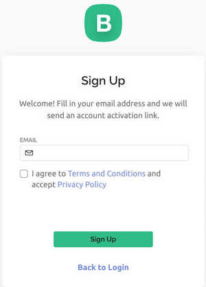
- Register my account on Blynk
- Open Arduino IDE, I installed Blynk Library
- Connect hardware
- Setting Blynk (The details below)
- PC setting
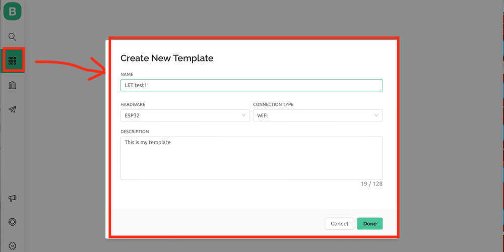
In PC, login Blynk
- Create Template
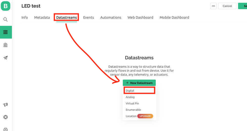
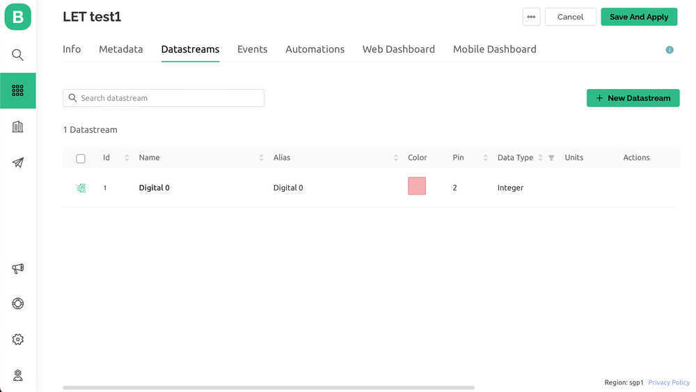
- Datastreams
- Setting the details from Blynk to each target device. In this time, I choose Digital
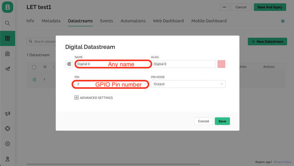
- Setting for LED
- Name: Any name is OK.
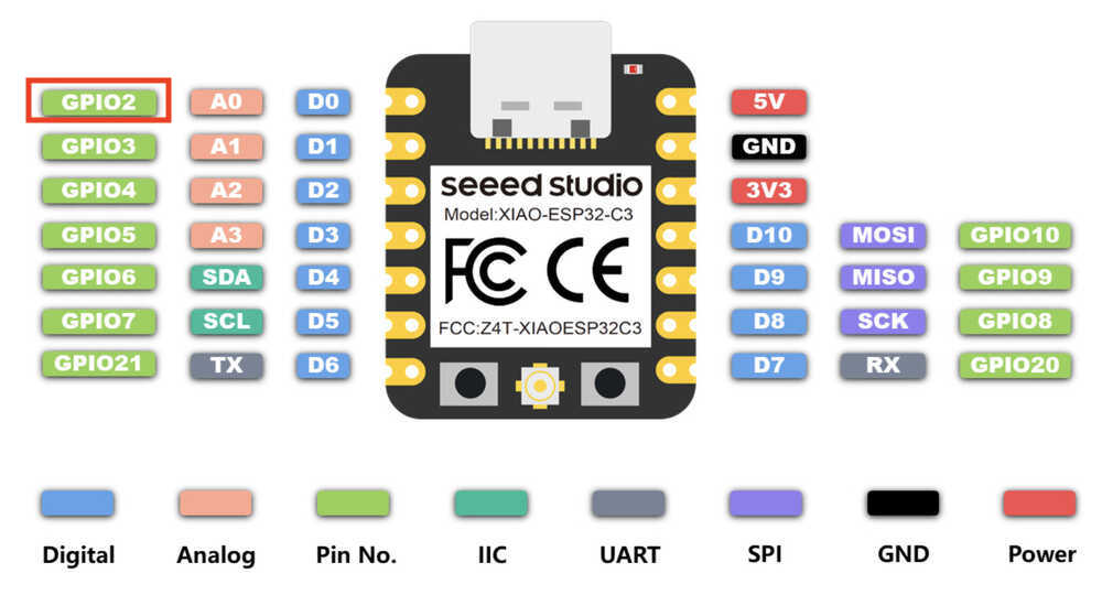
- PIN: 2 (For PIN, enter the GPIO number from the datasheet.)
- Pinout of XIAO ESP32C3 from Datasheet
- XIAO ESP32C3 Board that Hiroe Takeda made in Week09.
- Setting the details from Blynk to each target device. In this time, I choose Digital
- Web Dashboard
- Drag the Widget(switch and LED) to Dashboard and setting
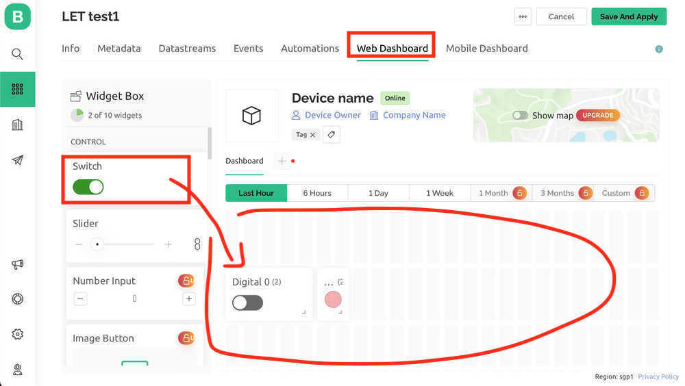
- Switch Settings details
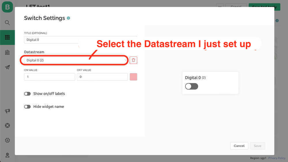
- LED Settings details
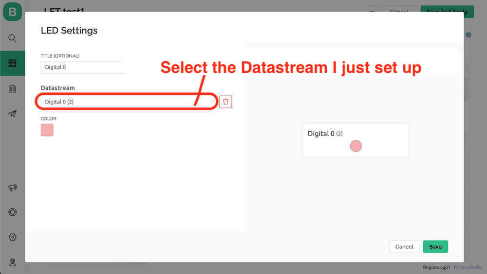
- Drag the Widget(switch and LED) to Dashboard and setting
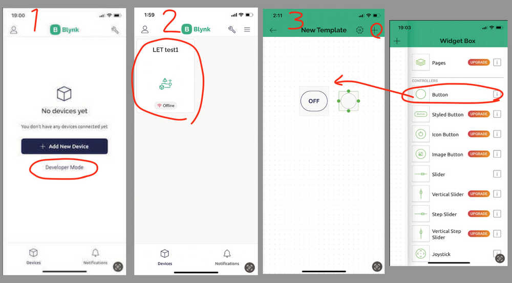
- Smartphone setting
Install Blynk App (Only the first time).
Then, Login Blynk App.
- Select “Debeloper Mode”.
- Choose template I made in PC. (-> Edit view of Dashboard is opened.)
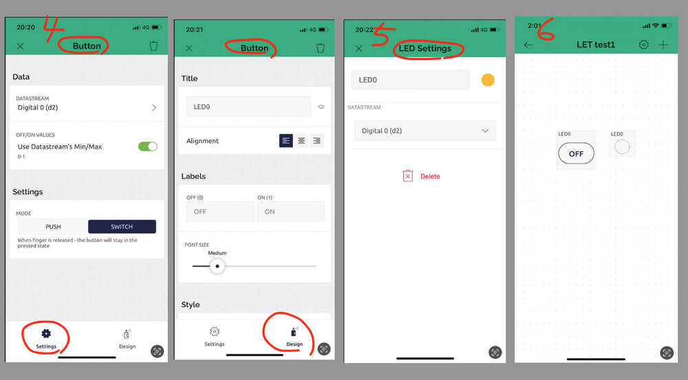
- Add Button and LED. (Button is a alternative of switch )
- Click Button and setting.
- Click LED and setting.
- Once the buttons and LEDs are tied to the pins configured on the PC, the setup is complete.
- Create a new device / Auth Token
- Return to the Blynk’ management page in PC to work again.
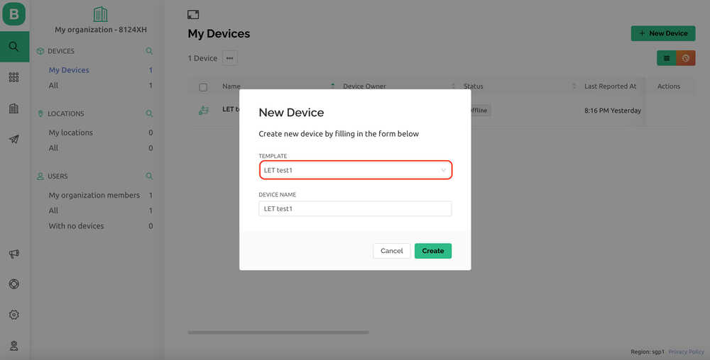
- Create a new device from template.
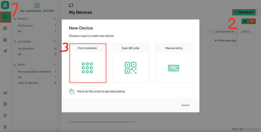
- Choose template.
- Auth Token is appeared.
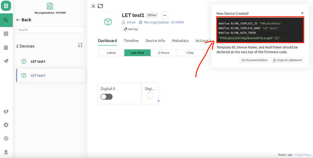 In order for Blynk to communicate with each target device, an Auth Token must be planted on the target device side.Copy this AuthToken and insert it into the Arduino IDE code.
- Arduino IDE
- Open Arduino IDE
- choose board “XIAO_ESP32C3”, Port is “/dev/cu.usbmodem1101” in this time.
- upload the code
- Code for Arduino IDE
- the citting code from hirunosannpo.blog.jp
- Replace AuthToken, Lines 7-9.
/*************************************************************
  This is a simple demo of sending and receiving some data.
  Be sure to check out other examples!
 *************************************************************/
// Template ID, Device Name and Auth Token are provided by the Blynk.Cloud
// See the Device Info tab, or Template settings
#define BLYNK_TEMPLATE_ID "TMPL6OcSMw4Jc"
#define BLYNK_TEMPLATE_NAME "LET test1"
#define BLYNK_AUTH_TOKEN "PRdtqk6zGHSiRgZ8ow4sNTmLeugmF-Oj"

// Comment this out to disable prints and save space
#define BLYNK_PRINT Serial

#include <WiFi.h>
#include <WiFiClient.h>
#include <BlynkSimpleEsp32.h>
#include <math.h>

char auth[] = BLYNK_AUTH_TOKEN;

// Your WiFi credentials.
// Set password to "" for open networks.
char ssid[] = "your wifi id";
char pass[] = "your wifi password";

BlynkTimer timer;

// the number of the LED pin
const int ledPin = 2;

// This function is called every time the Virtual Pin 1 state changes
BLYNK_WRITE(V1) ///LightPin:Relay_operates_on_LOW_Input_Voltage_coneccted_NC
{
  int buttonState = param.asInt();
  // Update state
  if(buttonState == HIGH){
     digitalWrite(ledPin, HIGH);
     Serial.println("HIGH");
  }else{
     digitalWrite(ledPin, LOW);
     Serial.println("LOW");
  }
}

// This function is called every time the device is connected to the Blynk.Cloud
BLYNK_CONNECTED()
{
  Serial.println("Connected!");
}
//////////////////////////////////////////////////////////////////////

void setup() {
  // Serial port for debugging purposes
  Serial.begin(115200);

  //pinMode setting
  pinMode(ledPin , OUTPUT);

  //WiFI Setting
  Blynk.begin(auth, ssid, pass);
  // You can also specify server:
  //Blynk.begin(auth, ssid, pass, "blynk.cloud", 80);
  //Blynk.begin(auth, ssid, pass, IPAddress(10,0,1,28), 8080);
  //Blynk.begin(auth, ssid, pass, IPAddress(10,0,1,28));

  // Setup a function to be called every second
  //  timer.setInterval(1000L, myTimerEvent);
}

void loop() {
  Blynk.run();
}
3.Processing
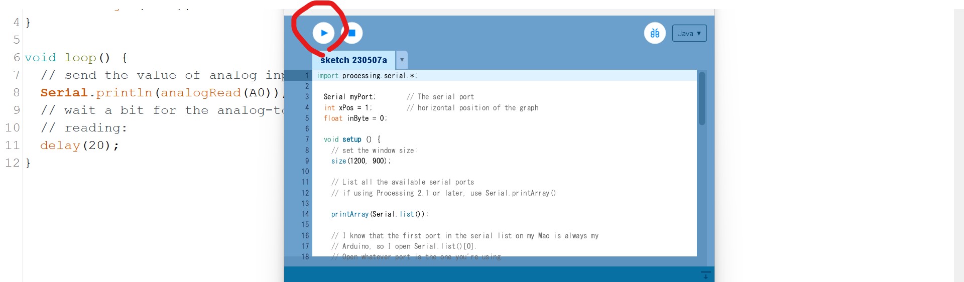
- Tried to use “Processing” to show analog data graphically by referring this instruction.
- The code for processing is here.
- On week 11, I made a small board for step response designed by Adrian (see this site). Then connected to my xiao esp32c board to read analog response.
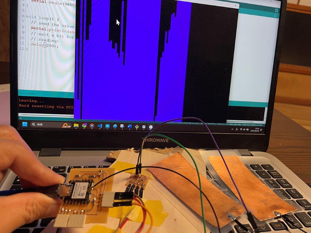
- This time I only used analog pin for taking analog input. And uploaded the sketch.
- Once uploaded the sketch to xiao board, then I run Processing sketch.
- Processing window shows graphic along the analog input.
- Processing shows data visually moving line, it helps intuitive understanding. But so far I just borrowed sample code and put my case in. I need to study more how I can show the graph better.
4. Compare tool options we used
Below is a brief comparison of the main differences between HTML/CSS/JavaScript, Blynk, and Processing that we tested.
4-1. UI and UX with HTML/CSS/JavaScript:
- It is widely used in the development of web-based user interfaces.
- High customizability.
- Requires relatively high development skills.
- HTML defines the structure of a web page; CSS defines its style (colors, fonts, layout, etc.); JavaScript is used to add dynamic elements to a web page (user interaction, animation, real-time updates, etc.).
4-2. Blynk:
- Simplifies control and management of IoT devices and allows intuitive operation via mobile apps.
- The drag-and-drop interface allows even those with limited programming skills to set up the device’s control system.
- Customizability is limited compared to HTML/CSS/JavaScript.
4-3. Processing:
- Processing is an open source programming language and development environment for integrating visual arts and programming.
- It is suitable for creative coding, including data visualization, digital art creation, and interactive media installation.