Week 11 - Group / Input devices
This is group assignment page of Mechanical Design and Machine Design (Kitakagaya students):
- Shin Masuoka
- Hiroe Takeda
Group assignment
- Probe an input device(s)’s analog and digital signals
- Document your work on the group work page and reflect on your individual page what you learned
I2C analysis (Hiroe Takeda)
Input device and IDE, I used
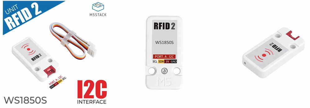
- RFID2
-
RFID2 is a radio frequency identification unit. Built-in WS1850S chip, working frequency is 13.56MHz. Supports reading card, writing card, recognition, recording, and encoding RF card Multiple functions such as authorization and authorization. Use magnetic field induction technology to realize non-contact two-way information interaction, read and verify the information of proximity cards.
-
Product Features
- Operating frequency: 13.56 MHz
- I2C data rate: Fast mode: up to 400 Kbit/s; High-speed mode: up to 3400 Kbit/s
- Transceiver buffer: 64 bytes
- Supported protocols: ISO14443A, MIFARE and NTAG
- Working temperature: -20℃-85℃
- Data storage:> 10 years
- Reading distance: <20 mm
- Development platform: Arduino, UIFlow(Blockly, Python)
- 2x LEGO compatible holes
- IDE
-
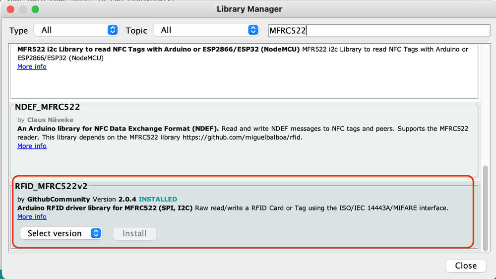
Library:
Install Library “RFID_MFRC522v2” that can Raw read/write a RFID Card or Tag using the ISO/IEC 14443A/MIFARE interface.
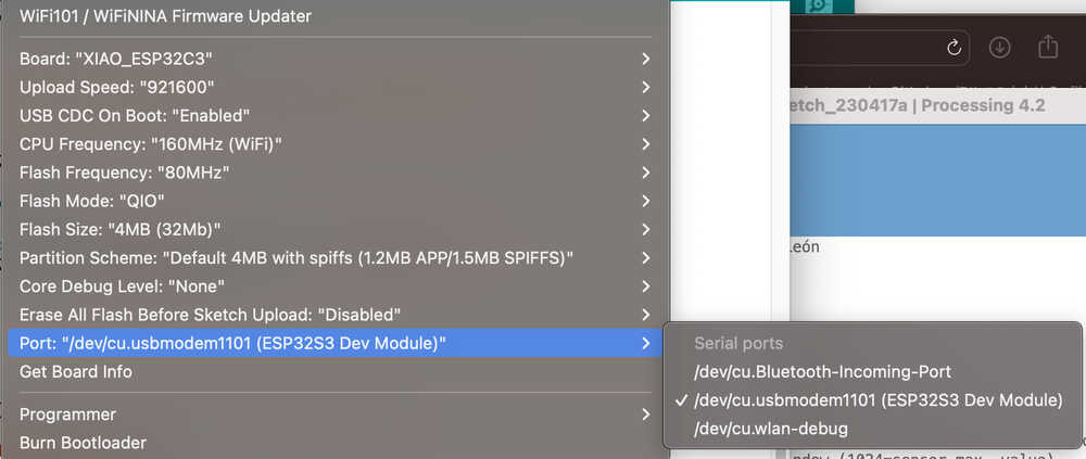
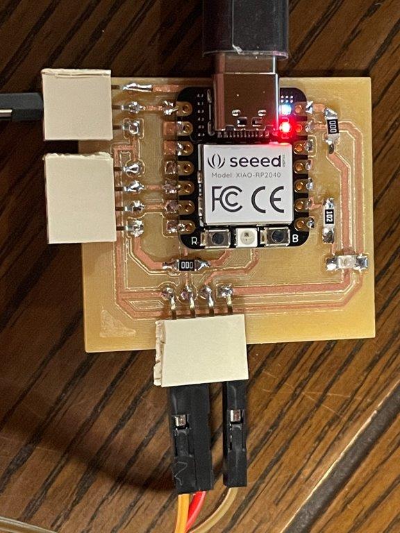
- Board
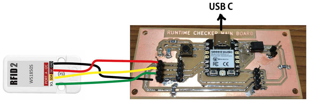
We use board that I designed Week09 Output device with Seeed Xiao ESP32C3.
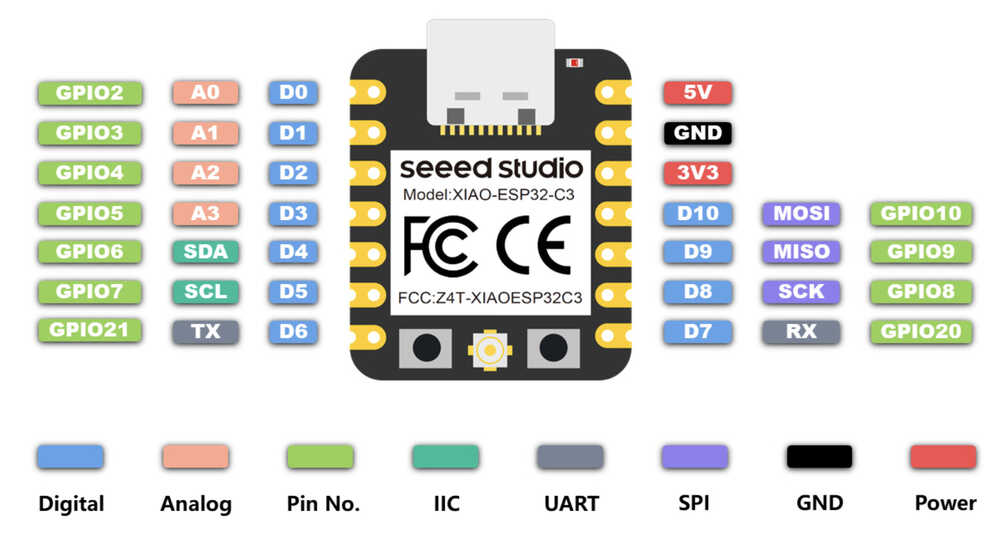
Pinout for Seeed Xiao ESP32C3
- Programming
- I generated a code in ChatGPT that reads the card and displays the UID of the card.
- Instruction to ChatGPT:
Attach Example code (RFID_MFRC522v2 > CustomI2C) in Arduino IDE, and ask to rewrite it for Xiao ESP32C and generate code.
- Instruction to ChatGPT:
- Programming code
#include <Wire.h>
#include <MFRC522v2.h>
#include <MFRC522DriverI2C.h>
#include <MFRC522Debug.h>

const uint8_t customAddress = 0x28;

MFRC522DriverI2C driver{customAddress, Wire}; // Use the standard Wire object for I2C driver.

MFRC522 mfrc522{driver}; // Create MFRC522 instance.

void setup() {
  Serial.begin(115200); // Initialize serial communications with the PC for debugging.
  while (!Serial);      // Do nothing if no serial port is opened (added for Arduinos based on ATMEGA32U4).

  Wire.begin(); // Initialize I2C with default SDA and SCL pins.

  mfrc522.PCD_Init();   // Init MFRC522 board.
  MFRC522Debug::PCD_DumpVersionToSerial(mfrc522, Serial); // Show details of PCD - MFRC522 Card Reader details.
  Serial.println(F("Scan PICC to see UID, SAK, type, and data blocks..."));
}

void loop() {
  if ( !mfrc522.PICC_IsNewCardPresent() || !mfrc522.PICC_ReadCardSerial()) {
    return;
  }

  MFRC522Debug::PICC_DumpToSerial(mfrc522, Serial, &(mfrc522.uid));
}
- Input programming code and upload, and I put the Mifare card on RFID2.
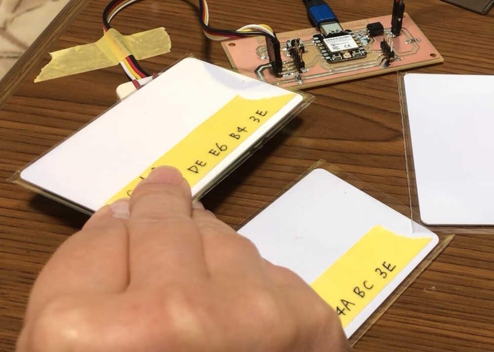
- Serial monitor in Arduino IDE show the card UID.
Card A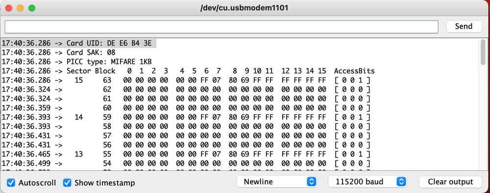 Card B
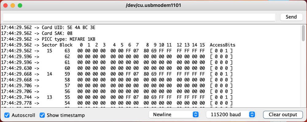 The photo of card with UID that I know with the programming.
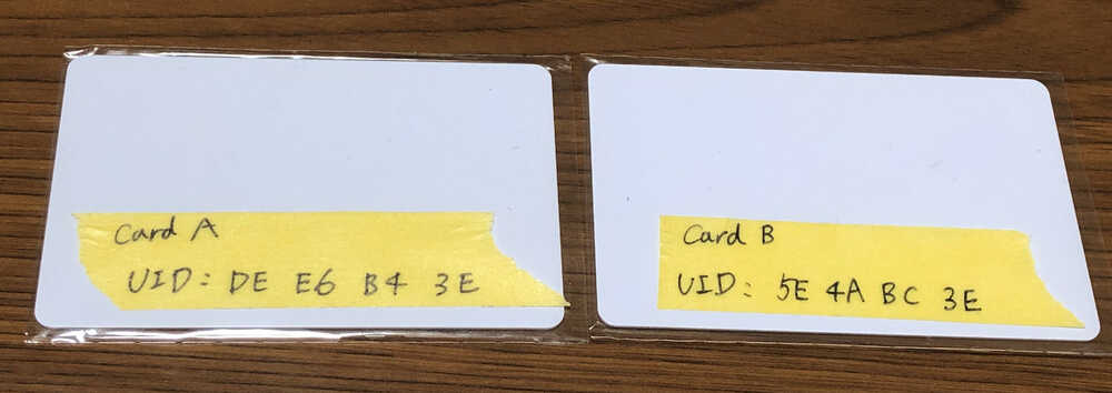
The programming test is success!
- Decode I2C serial data on the Rigol 1054Z oscilloscope
I refer to Tutorial by learnelectronics: How to decode I2C serial data on the Rigol 1054Z oscilloscope and connect as below and start I2C analysis with oscilloscope.
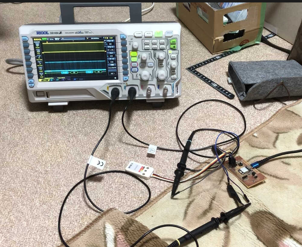
As below Video show, I got the I2C data. But I couldn’t understand what the number mean…
Step resoponse
-
We added and made step response electrodes and Adrian’s board on Shin Msuoka’s board.
-
We measured something by step response, traced by serial plotter.
- The board was designed at week8
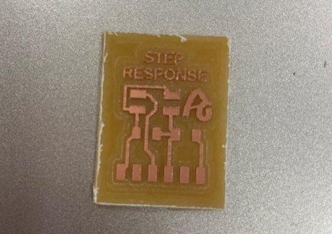
Making the sensor
-
In this Fab academy 2023, we heard about sensor used “step response” several times. It sounded interesting because it merely 2 sheets of copper, but measure many things.
-
We referred Adrian’s site
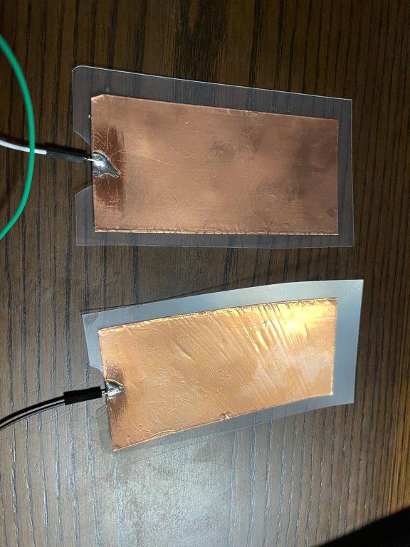
- Prepared a board for step response
- Prepared copper tape and created 2 electrodes. We made 50 x 100 mm electrodes, thickness is 0.03mm.

### Program referred - We referred Adrian’s site and copied programs. Then modified it for xiao 2040 whic
//tx_rx03  Robert Hart Mar 2019.
//https://roberthart56.github.io/SCFAB/SC_lab/Sensors/tx_rx_sensors/index.html

//Modified by Adrián Torres Omaña
//Fab Academy 2021
//Step Response TX, RX
//Adrianino
//ATtiny1614

//Modified by Shin Masuoka
//Fab Academy 2023
//Step Response TX, RX
//Adrianino
//xiao rp 2040

//  Program to use transmit-receive across space between two conductors.
//  One conductor attached to digital pin, another to analog pin.
//
//  This program has a function "tx_rx() which returns the value in a long integer.
//
//  Optionally, two resistors (1 MOhm or greater) can be placed between 5V and GND, with
//  the signal connected between them so that the steady-state voltage is 2.5 Volts.
//
//  Signal varies with electric field coupling between conductors, and can
//  be used to measure many things related to position, overlap, and intervening material
//  between the two conductors.
//

long result;   //variable for the result of the tx_rx measurement.
int analog_pin = 26; //  Analog pin of xiao rp 2040
int tx_pin = 0;  //     TX pin of xiao rp 2040
void setup() {
pinMode(tx_pin,OUTPUT);      //Pin 2 provides the voltage step
Serial.begin(115200);
}

long tx_rx(){         //Function to execute rx_tx algorithm and return a value
                      //that depends on coupling of two electrodes.
                      //Value returned is a long integer.
  int read_high;
  int read_low;
  int diff;
  long int sum;
  int N_samples = 100;    //Number of samples to take.  Larger number slows it down, but reduces scatter.

  sum = 0;

  for (int i = 0; i < N_samples; i++){
   digitalWrite(tx_pin,HIGH);              //Step the voltage high on conductor 1.
   read_high = analogRead(analog_pin);        //Measure response of conductor 2.
   delayMicroseconds(100);            //Delay to reach steady state.
   digitalWrite(tx_pin,LOW);               //Step the voltage to zero on conductor 1.
   read_low = analogRead(analog_pin);         //Measure response of conductor 2.
   diff = read_high - read_low;       //desired answer is the difference between high and low.
 sum += diff;                       //Sums up N_samples of these measurements.
 }
  return sum;
}                         //End of tx_rx function.

void loop() {

result = tx_rx();
result = map(result, 8000, 11000, 0, 1024);  //I recommend mapping the values of the two copper plates, it will depend on their size
Serial.println(result);
delay(100);
}