Week 8 - Group / Electronics Production
This is group assignment page of Electronics Production (Kitakagaya students) :
- Sosuke Kanegae
- Shin Masuoka
- Hiroe Takeda
Group assignment
- characterize the design rules for your in-house PCB production process
- extra credit: send a PCB out to a board house
The Machine
- We use Roland MODERA model MDX-40 (Update to MDX-40A)
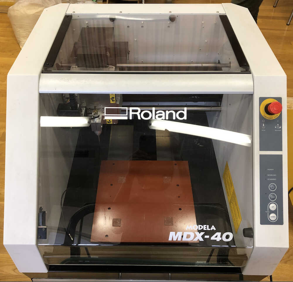
| machine spec | Description |
|---|---|
| Cuttable material | Resins such as chemical wood and modeling wax (metal not sup- ported) |
| Work area | 305 (x) x 305 (y) x 105 (z) mm |
| Workpiece table size | Width x depth: 305 × 305 mm |
| Loadable workpiece weight | 4kg |
| Operating speed | XY axis: 7 to 3000 mm/min. Z axis: 7 to 1800 mm/min. |
| Spindle Motor | DC brushless motor, max 100W |
| Spindle rotation | 4,500 to 15,000 rpm |
| Overall Machine Size | 669 x 760 x 554 mm |
| Machine Weight | 66kg |
| Software resolution | 0.01mm/step (RML-1) 0.001mm/step (NC code) |
| Control command sets | RML-1, NC code |
| Computer | Model preinstalled with Windows 7, Vista (32/64-bit edition) or XP, or upgraded computer originally preinstalled with Windows XP or later |
Software
- We use VPanel for MDX-40A
Material
-
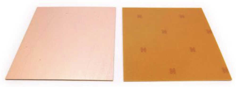
We use FR1 (Paper phenol), one side
- Size: 100 x 150 x 1.6(t) mm
- Cu thickness: 35um = 0.035mm
-
NOTE:
- FR = Flame Retardant
- FR grades are described by “FR-numbers”. The numbers range from 1 to 5, with FR-5 being the most flame-resistant grade. The higher the number, the less flammable it is.
Endmill
- We use below Endmill.
| - | End mill | Where to buy | Maker : model number |
|---|---|---|---|
| Interior (Board outline) | Diameter 1.0 mm (number of flutes: 2) |
MISUMI | OSG: WXL-2D-DE-1 |
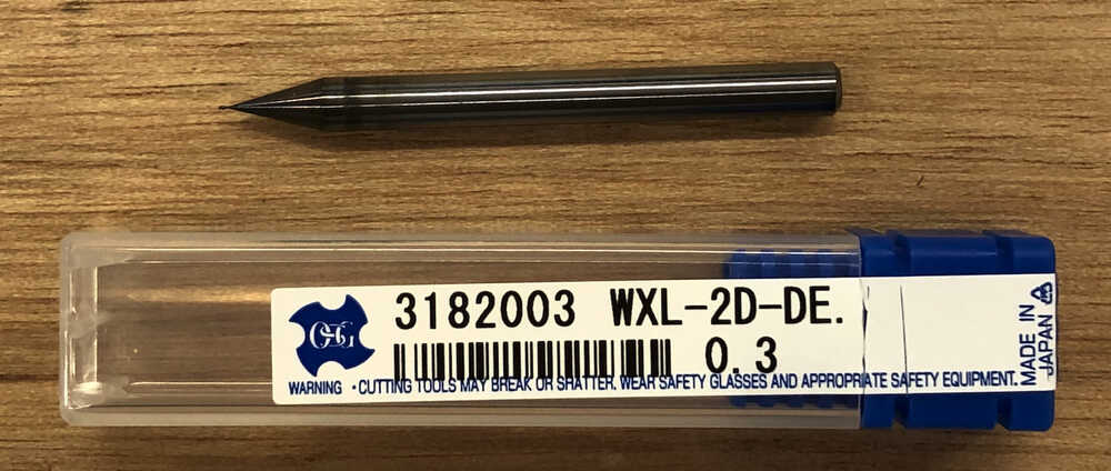
| Trace | Diameter 0.3 mm (number of flutes: 2) |
MISUMI | OSG: WXL-2D-DE-0.3 |
- NOTE:
- Although we wanted to use D0.4mm mill for Trace, which is recommended by Fab Academy, Trace cutting was not possible for chip of FT230XS, so We used D0.3 mill for Trace.
- Proper use of end mill at Fab Lab West-harima
| title | which brand | Reason |
|---|---|---|
| Diameter <1mm | Use of quality end mills from tool manufacturers (OSG, Mitsubishi Materials, Fujikoshi, etc.) | - Use of quality end mills from tool makers such as OSG, Mitsubishi Materials, Fujikoshi, etc., as we feel that shop-planned low-cost end mills are inconsistent in quality and less durable |
| Diameter <3mm | Store brand low-cost end mills | - Feel that even shop-brand low-cost end mills are of sufficient quality and durability |
Therefore, FabLab West-harima use tool makers mill for milling of PCB board.
-
Photo:
-
OSG WXL-2D-DE Datasheet
Depth of Cut
- refet to datasheet
Calculate feed rate and spindle speed by MDX-40A spec
-
Calculate feed rate and spindle speed by MDX-40A spec, from tool datasheet.
- Chipload = feed rate / Spindle Speed / number of flutes
- In case of:- Endmill : OSG WXL-2D-DE-0.3 & Material: FR1
Process of calculation:
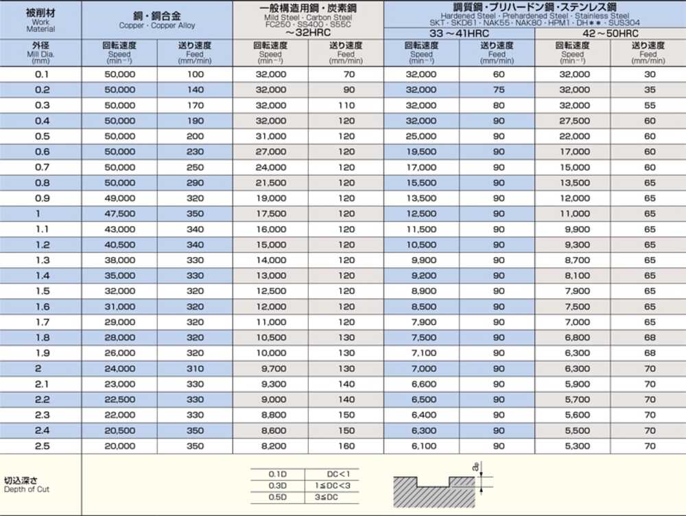
- Read the toolmaker’s data sheet (copper alloys).
- In Toolmaker’s data sheet
- refer to Diameter 0.3mm and Cupper and find chipload for the mill.
- Chipload (0.0017 = 170(mm/min) / 50000(min-1) / 2)
- Depth of Cut (0.1D for Diameter < 1mm) ([e.g.]for 0.3D, 0.1x0.3(D) = 0.03)
- Calculate feed rate and spindle speed by MDX-40A spec.
- MDX-40A spec; Spindle speed max 15000 min-1
- Calculate feed rate at which chip load becomes 0.0017 (data sheet chip load) at spindle speed 15000
- Feed rate = 51 mm/min (0.85 mm/sec) = 0.0017x15000min-1 x2
NOTE: - Considering finish, tool life, etc., it is desirable to machine with parameters based on the recommended values in the data sheet.
MODS
In this time, we use new MODS to create tool path for test cut trace and save file, using MDX-40A.
Create tool Path, using MODS
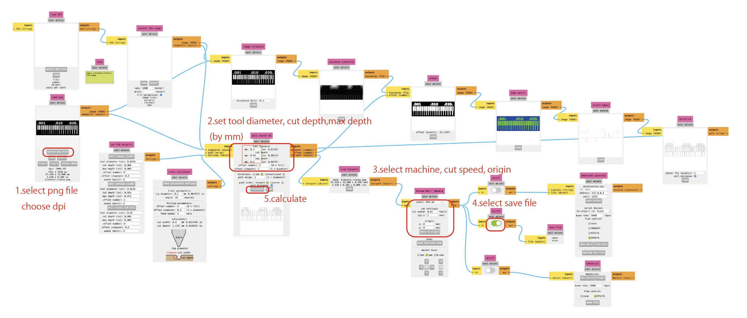
new MODS open
Right click > Open program > Open Program > Roland MDX mill “PCB”
1. Select png file of Trace, and choose dpi
2. Set tool diameter(0.3mm), cut depth(0.83mm), max depth(0.2mm)
3. select machine(MDX-40), cut speed(0.85), origin(x0,y0).
4. select save file
5. calculate
Then, we could get the tool path for the test cut.
NOTE
- WebSocket Device/Print:
- Tried to connect device, but could not.
- WebUSB:
- It is possible to move to XYZ by MODS operation.
- However, later on, the control was no longer possible with the original software, so control via Web USB was given up. (see below what happened)
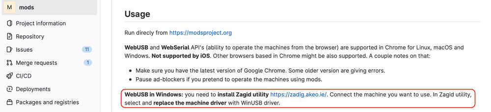
- What Happened with WebUSB
The MDX-40 is supposed to be controlled with the original software (VPanel), but after installing the Zagid utility, which is required to control the new MODS via WebUSB, the original software could no longer control it. Therefore, we gave up control via WebUSB.
PCB design rule and milling test
-
We did not have clear PCB design rule. Then we set as below based on tutor’s advice.
- Pattern line width
- Power line 0.8mm, signal line 0.4mm
- Gap 1.2d
- Edge cut: Use 1mm mill
- Pattern line width
-
For confirming our milling machine [Roland DX-40]’s performance, we made test data as below.
Both pattern and gap start from 0.1mm to 1mm with 0.05mm steps.
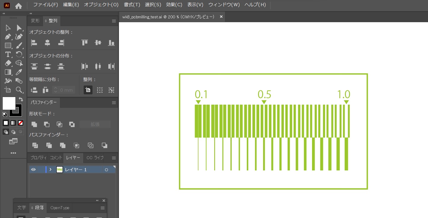
- The result is as follows; cutting speed:150mm/min end mill diameter:0.3mm Cut depth:0.2mm
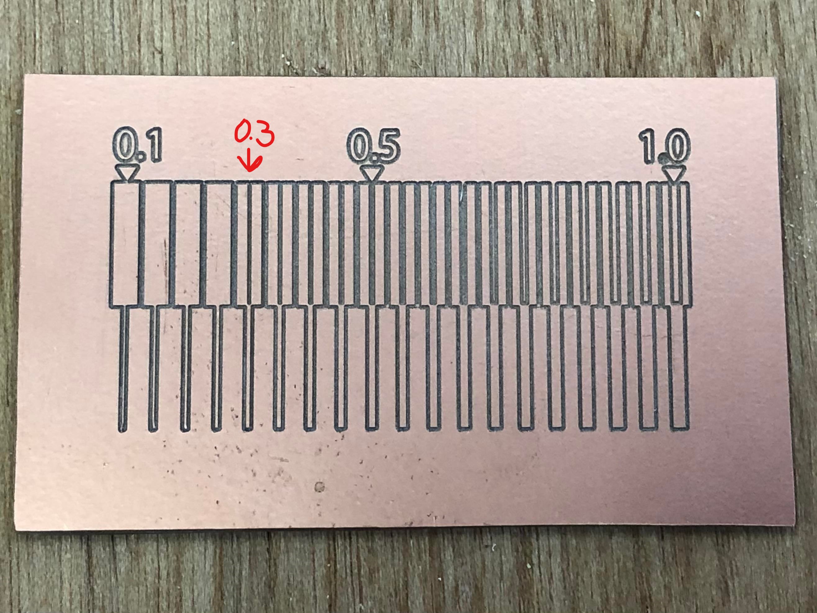
- We use 0.3mm diameter end mill. This is why the gap under 0.3mm was not possible.
- On the other hand, even 0.1mm line well milled.