Week 6. Group / Electronics Design
This is group assignment page of Electronics Design (Kitakagaya students) :
- Sosuke Kanegae
- Shin Masuoka
- Hiroe Takeda
Group assignment
- use the test equipment in your lab to observe the operation of a microcontroller circuit board
-The microcontoroller we used
- M5STACK ATOM Matrix
- micro:bit
- Seeed Studio XIAO RP2040
-The test equipment we used
-
Oscilloscope DS1054Z of RIGOL.
- The Spec of DS1054Z
- frequency band : 50MHz
- Number of analog channels: 4
- Real-time sample rate : 1GSa/s
- Maximum memory length :24 Mpts
- Waveform acquisition rate : 30,000 wfms/s
- The Spec of DS1054Z
-About Oscilloscope
- An oscilloscope is an electronic test instrument that displays the value of an electric signal over time.
- The display of the oscilloscope shows the amplitude (usually voltage) of a signal on the Yaxis, and time along the Xaxis.
- Oscilloscopes are commonly used to:
- measure shape of a waveform (a graph of voltage over time)
- measure amplitude and frequency of a signal
- and detect glitches and noise in a signal
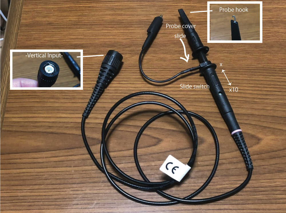
Prepare - Probe Calibration
- Connect probe to the main unit of DS1054.
- Probe has an orientation, so be careful NOT to connect in the reverse direction.
- How to connect
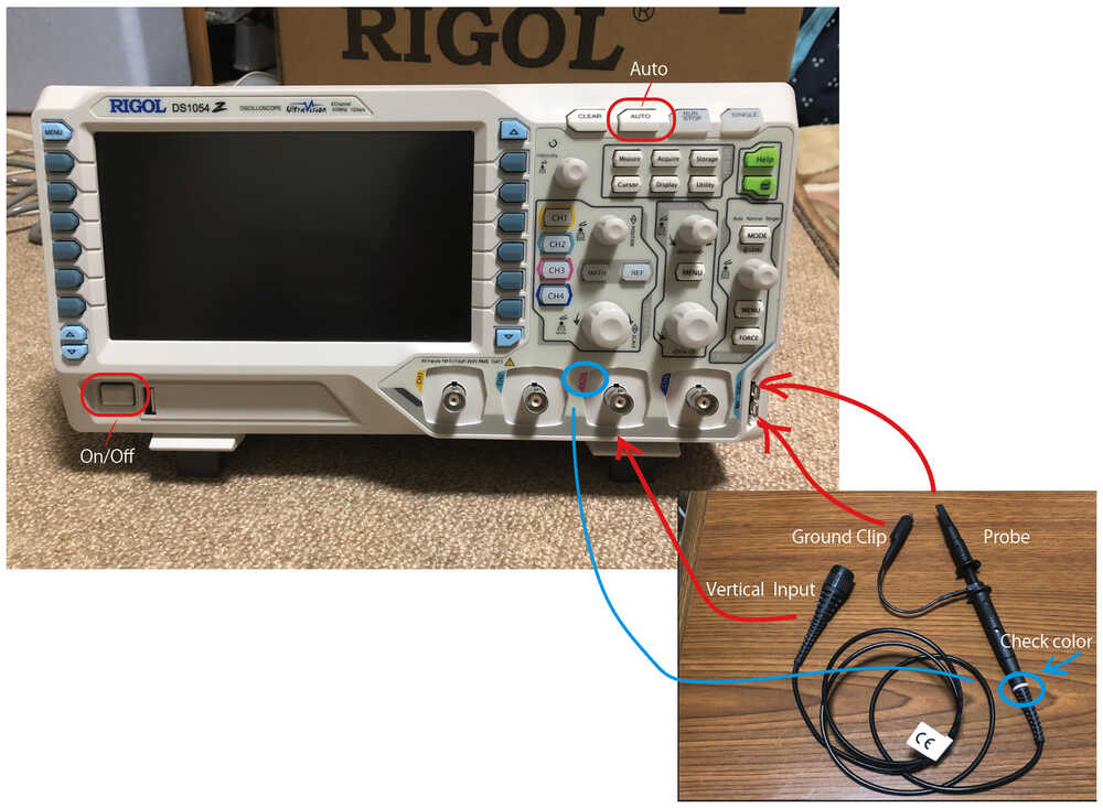
- About Probe switch, we choose “x10”.
-
Then Turn on the Power, and Push “Auto” bottom.
-
If the waveform is not flat, turn the probe screw and adjust until the waveform is flat.
- Calibration is complete when waveform is straightened.
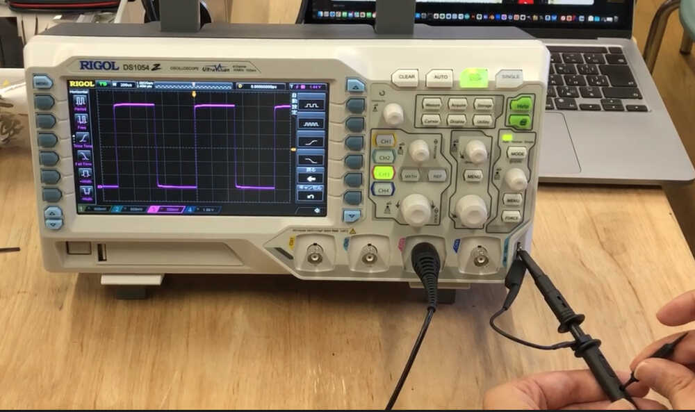
TEST1, using micro:bit
We programmed with Microsoft MakeCode, 1 output, and upload to micro:bit, then we observed the waveform with DS1054Z. And I could confirm the waveform the same as programming. The Process is below.
- Programming
-
Programming by “Write a digital (0 or 1) signal to a pin0” with Microsoft MakeCode. Then download it, then upload it to micro:bit.
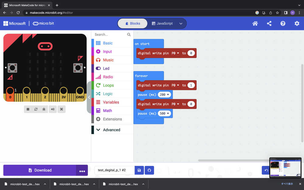
- About the code block, refer to Digital Write Pin
- About the details of Process of the programming, refer to Week04 Group assigntment
- In case of Javascript and Python.

-
Connect oscilloscope to micro:bit
-
In case of this programming, we connected as follows.
oscilloscope
DS1054Zmicro:bit Probe P0 GND clip GND
-
-
Check the waveform of the oscilloscope
- Push “Auto” bottom, and observe displays the value of an electric signal.
- We can see the waveform as same as Programming as below video.
- Video
TEST2, using Seeed Studio XIAO RP2040
We programmed by Arduino IDE, 3 outputs, and upload to Seeed Studio XIAO RP2040, then we observed the waveform with DS1054Z. And I could confirm the waveform the same as programming. The Process is below.
- Programming (with Arduiono IDE)
- The process programming is in Week04 Group assigntment
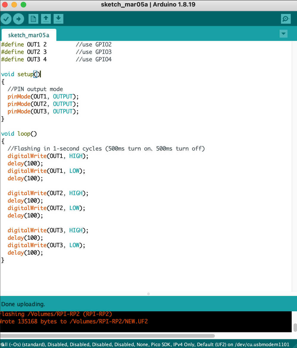
- Programming code is below.
#define OUT1 2         //use GPIO2
#define OUT2 3         //use GPIO3
#define OUT3 4         //use GPIO4

void setup()
{
  //PIN output mode
  pinMode(OUT1, OUTPUT);
  pinMode(OUT2, OUTPUT);
  pinMode(OUT3, OUTPUT);
}

void loop()
{
  //Flashing in 1-second cycles (500ms turn on、500ms turn off)
  digitalWrite(OUT1, HIGH);
  delay(100);
  digitalWrite(OUT1, LOW);
  delay(100);

  digitalWrite(OUT2, HIGH);
  delay(100);
  digitalWrite(OUT2, LOW);
  delay(100);

  digitalWrite(OUT3, HIGH);
  delay(100);
  digitalWrite(OUT3, LOW);
  delay(100);
}
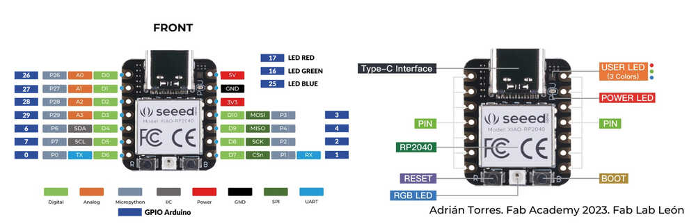
Then Connect oscilloscope to Seeed Studio XIAO RP2040 with Jamper wire and pin.
| oscilloscope DS1054Z |
Seeed Studio > XIAO RP2040 |
|---|---|
| Probe | GPIO 2 |
| Probe | GPIO 3 |
| Probe | GPIO 4 |
| GND clip | GNG |
About the GPIO number, and find it in Ardian Torres site, and it helpes us a lot.
We observed the waveform, we can see the waveform as same as Programming, showing below video.