10. Mechanical Design, Machine Design
Part one : Assignments
-
Mechanical Design
-
Group assignment:
-
Design a machine that includes mechanism + actuation + automation + application
-
Build the mechanical parts and operate it manually.
-
Document the group project
-
Individual assignment:
-
Document your individual contribution.
-
Machine Design
-
Group assignment:
-
Actuate and automate your machine.
-
Document the group project
-
Individual assignment:
-
Document your individual contribution.
Part two : What I did
- Group assignment:
To see our group assignment click here
- Individual assignment:
For this week’s assignment, we chose to design a light-powered turntable. to access the group’s work page. For this week’s work, we chose to design a turntable connected to a smartphone to automatically take photos and scan 3D objects. Click here to access the group’s work page. I’m in charge of programming the machine. Generally speaking, we chose to use a XIAO RP2040 associated with A4988 drivers to drive a NEMA 17 stepper motor connected to a telephone via an earpiece with a relay that simulates the action of clicking on a push-button to take a photo.
Machine presentation
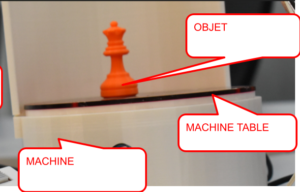
The machine we’ve designed is a turntable connected to a smartphone for automatic photo-taking and 3D scanning of objects.
Operation
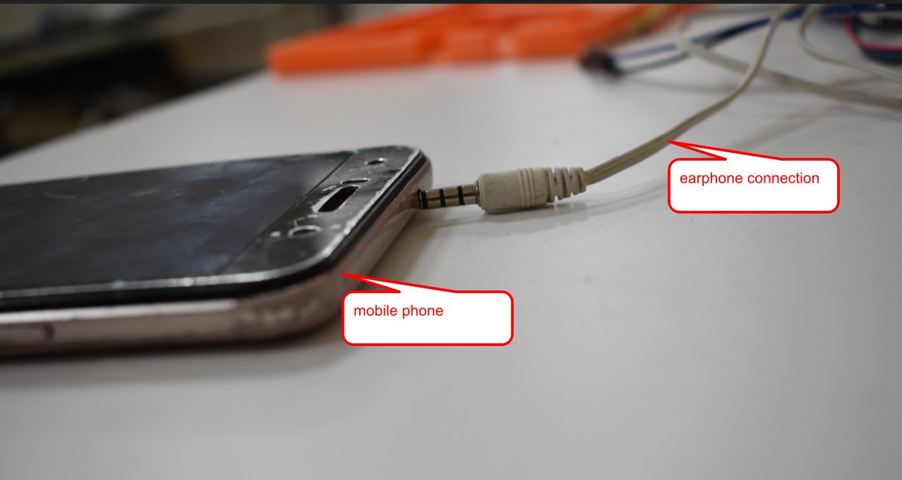
- Once the machine has been powered up, we connect a smartphone to the machine via a jack connector (earphone).
- Then we open the Krigi engine 3D scan application.
- place an object on the turntable
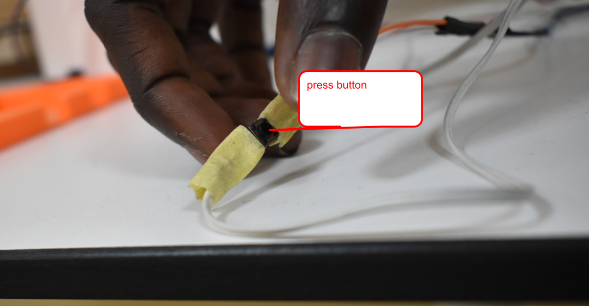
- Finally, we press a push-button that switches a relay every 5s to simulate pressing an earphone button to take a photo.
-
The sample of mobile 3D scanner APPS
-
APPS 01
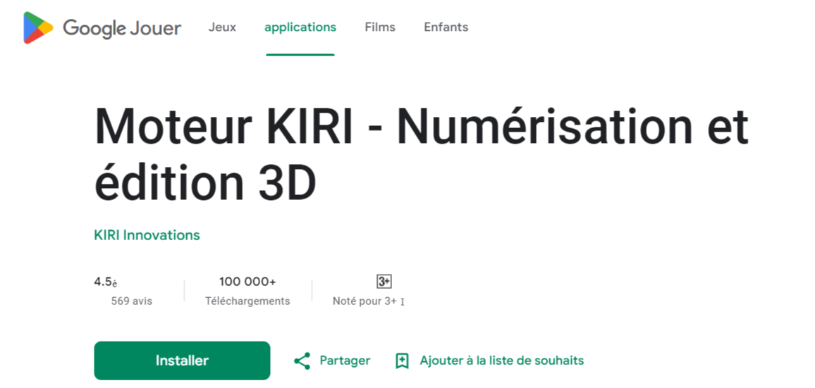
- APPS 02
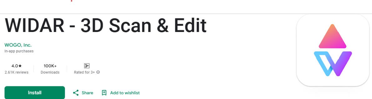
CLICK HERE TO GET IT ON PLAY STORE
Programming
Before we start programming, we’ll introduce the various components we’ll be using.
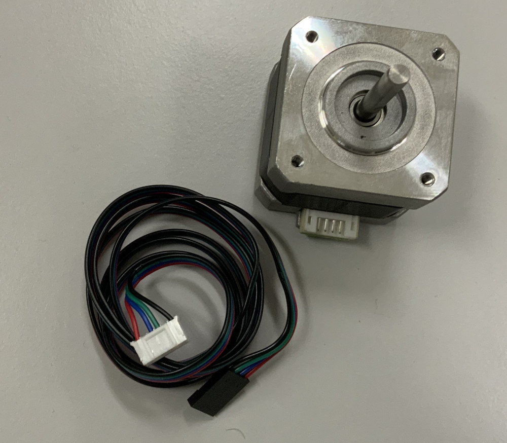
- Nema 17 stepper motor
For our machine we used a Nema 17 stepper motor as shown below:
Electrical specification
-
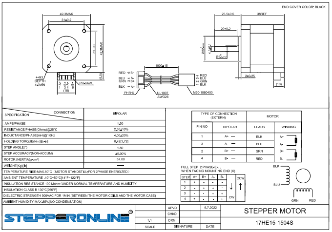
Manufacturer’s part number: 17HE15-1504S
-
Motor type: Bipolar Stepper
-
Stepping angle: 1.8 deg
-
Holding torque: 42Ncm(59.49oz.in)
-
Current/phase: 1.50A
-
Resistance/phase: 2.3ohms
-
Inductance: 4.0mH ± 20%(1KHz)
Physical specification
- Dimensions: 42 x 42mm
- Motor length: 38mm
- Shaft diameter: Φ5mm
- D-cut length: 20mm
- Front shaft length: 23.5mm
- Number of cables: 4
- Cable length: 1000mm
- Weight: 280g
Here is an image of the engine data sheet for more details click here
- Relay
A relay is an electronic device with an electromagnet at its heart. A relay can be thought of as an electric lever; you turn it on with a relatively small current, and it turns on another device with a much larger current. we have chosen to use the RELAY SONGLE SRD-05VDC-SL-C 10A as shown below.

- smartphone earphone
for this equipment we have modified it and connected it to our relay as shown below
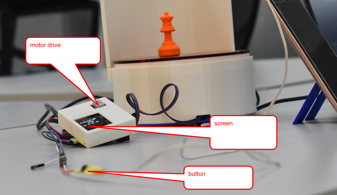
- The machine’s electronic control board. This is a printed circuit essentially made up of a XIAO RP2040, an A8209 stepper motor driver and an OLED display.
for more details on its design and manufacture please refer to
To program our XIAO RP2040 microcontroller, we chose Arduino IDE.
To do this, we proceeded as follows:
Arduino IDE installation and configuration
The Arduino software is an open source Integrated Development Environment (IDE) and free, downloadable from the official Arduino website choose version 1.8.19 as indicated below.
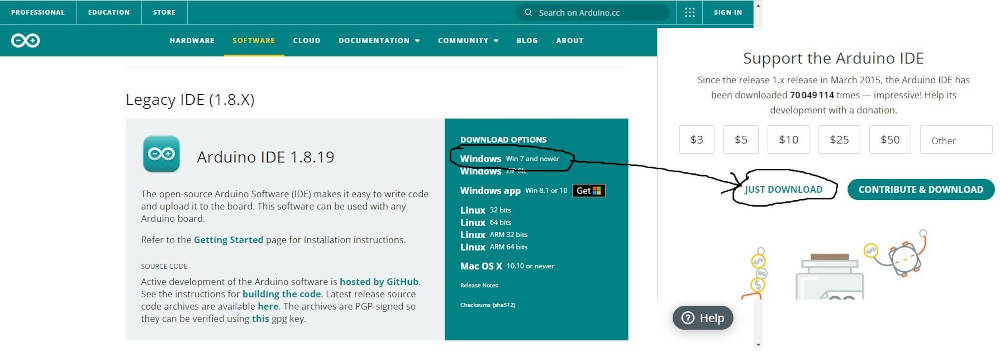
For the installation you just have to click on next. If all goes well you should have the display below.

The Arduino IDE allows you to edit a program, compile this program in the machine language, upload the program in the memory of various microcontrollers. The uploading is done via the USB port of the computer.
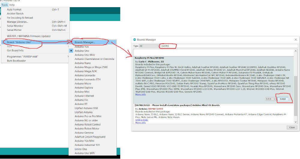
Once Arduino IDE is installed we will move on to adding the Seeed Studio XIAO RP2040 board package to Arduino IDE.
- Launch Arduino IDE, go to File > Preferences, and fill Additional Boards Manager URLs with the url below:
https://github.com/earlephilhower/arduino-pico/releases/download/global/package_rp2040_index.json

Navigate to Tools-> Board-> Boards Manager…, type the keyword RP2040 in the searching blank. Select the lastest version of Raspberry Pi Pico/RP2040 and install it.
Now that Arduino is installed and configured, we can move on to programming.
As far as programming is concerned, we started by testing the stepper motor’s rotation parameters, i.e. the time it takes to rotate one step.
For programming, we used the Arduino IDE software.
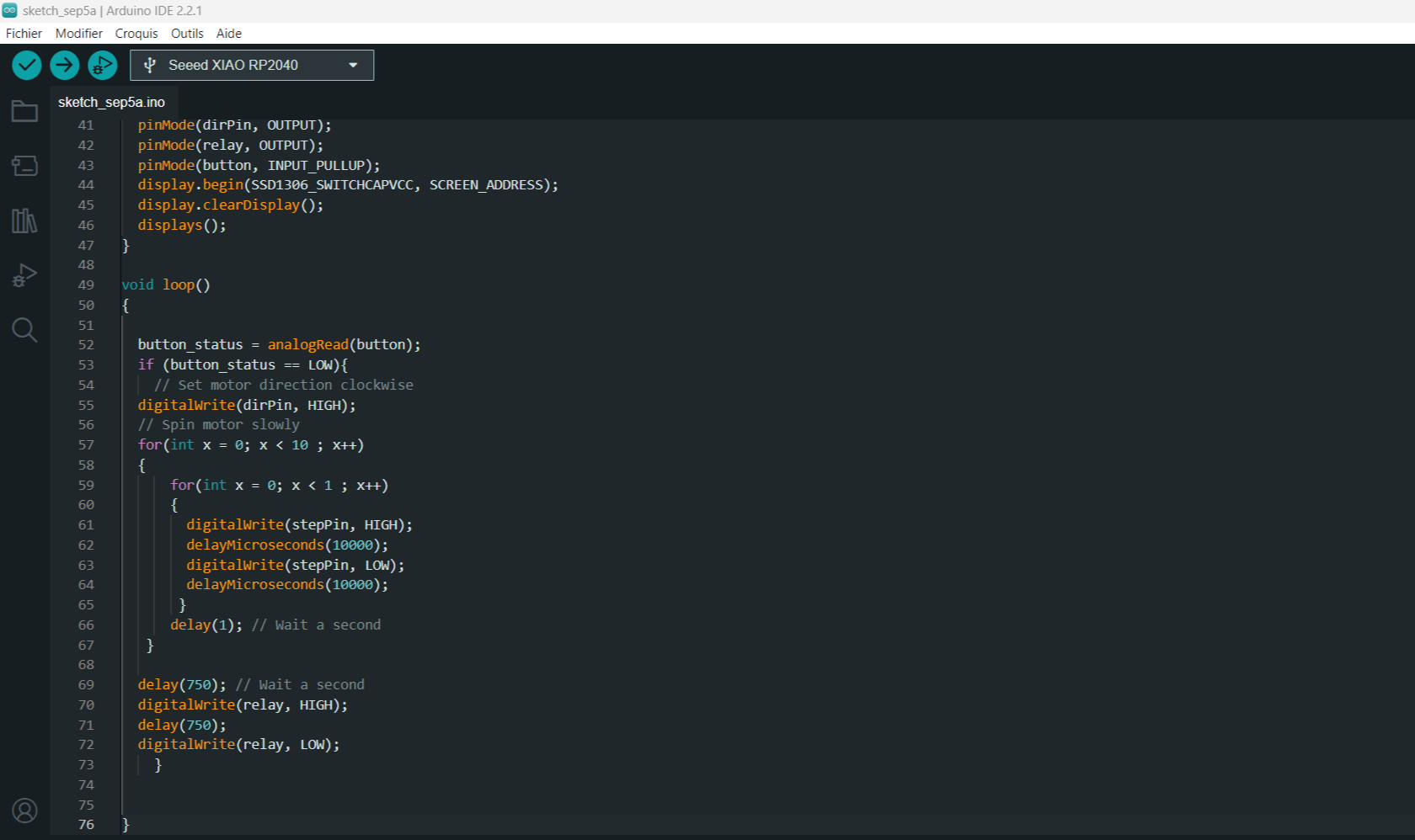
Our system works simply: when the push-button is pressed, the turntable rotates a certain number of steps and stops. Then a relay is activated for half a second to close the electronic circuit of an earpiece, enabling the phone to take a picture. at the end, the cycle starts again until the defined number of positions is reached.
here’s our program.
| Arduino_xiao_RP2040_program_1.ino | |
|---|---|
1 2 3 4 5 6 7 8 9 10 11 12 13 14 15 16 17 18 19 20 21 22 23 24 25 26 27 28 29 30 31 32 33 34 35 36 37 38 39 40 41 42 43 44 45 46 47 48 49 50 51 52 53 54 55 56 57 58 59 60 61 62 63 64 65 66 67 68 69 70 71 72 73 74 75 76 | |
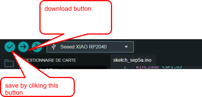
- download this code by clicking on this button
Explanation of the code
-
The code begins by defining the XIAO RP2040 pins to which the STEP and DIR pins of the stepper motor drivers are connected, as well as the sensor pin. A variable called stepsPerRevolution is also defined. In our case, it’s equal to 200.
- you need some libraries
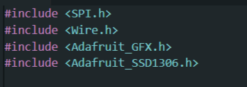
1 2 3 4 5 6 | |
- In the setup section, all motor control pins are configured as digital OUTPUT and the button pin to INPUT.
1 2 3 4 5 6 7 | |
- Controlling the Spinning Direction: To control the spinning direction of the motor, the DIR pin is set HIGH or LOW. A HIGH input turns the motor clockwise, while a LOW input turns it counterclockwise.
1 | |
- Controlling Speed: The frequency of pulses sent to the STEP pin determines the speed of the motor. The higher the pulse frequency, the faster the motor runs. A pulse is simply pulling the output HIGH, waiting a few milliseconds, then pulling it LOW and waiting again. By adjusting the delay, you can alter the frequency of the pulses and thus the speed of the motor.
1 2 3 4 5 6 | |
