12. Molding and Casting
Part one : Assignment
Groupe assignment:
-
Review the safety data sheets for each of your molding and casting materials
-
Make and compare test casts with each of them
Individual assignment:
- Design a mold around the stock and tooling that you’ll be using, mill it (rough cut + (at least) three-axis finish cut), and use it to cast parts.
Part two : Groupe assignment
To see our group assignment click here
Part three : Individual assignment
1. Objective
for this week I will make a mold for a key ring.
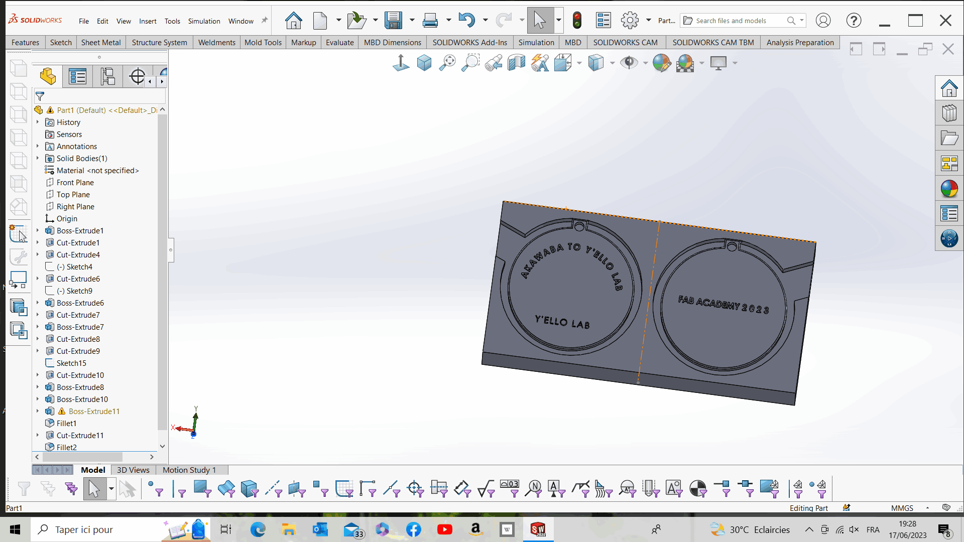
2. Modeling
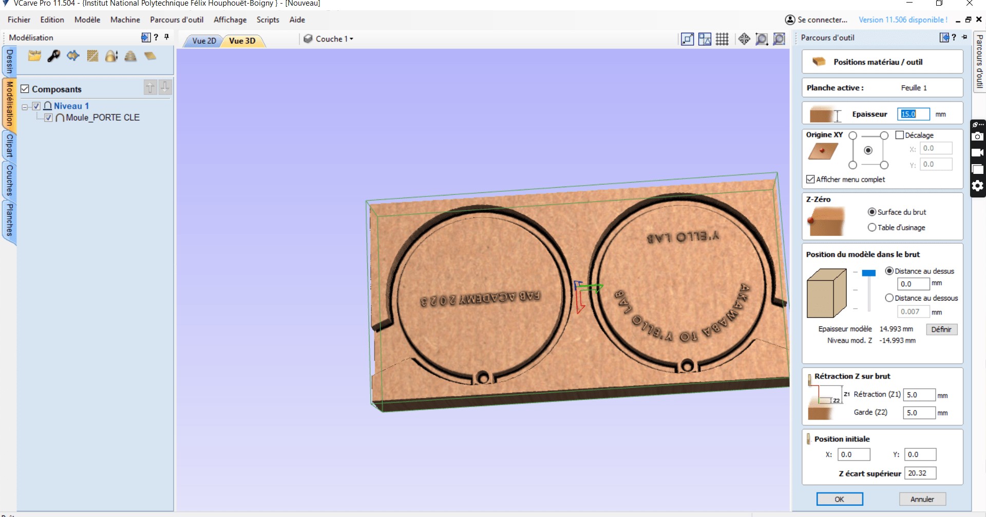
We used Solidworks computer-aided design software to model the mold. For more details please refer to the Week 3 (Computer-controlled Cutting) web page. Here are the final results of our mold design.
3. Mold machining
To machine our mold, we chose to use the ROLAND SRM-20 CNC milling machine in our Fab lab. To do this, we generated the toolpath using V-carve software. Here’s how we did it:
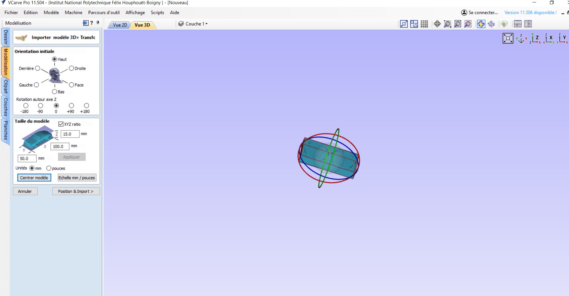
- setp 1: We opened the stl file of our mold with v-carve and set the import parameters as shown below
Choose one of the 6 options to determine the most appropriate direction on the model that defines the top surface (top Z) you want to use when converting it to a Component.
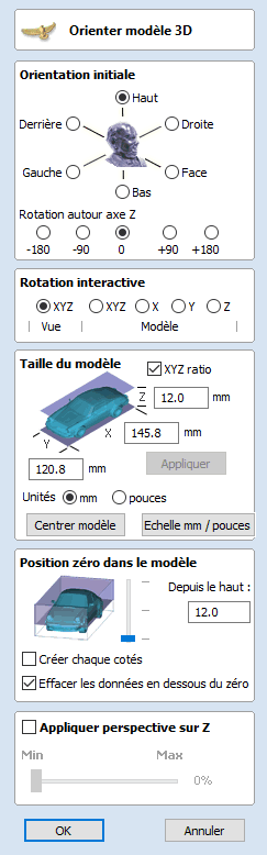
The default XYZ-View choice allows you to left-click in the 3D view to rotate your view so you can examine the part from different angles. Using this function will not change the orientation of the part to be imported. If you select one of the other four options above the word “Model”, the actual orientation of the imported part will be adjusted. If you choose the XYZ option, rotation around all three axes will be allowed simultaneously, with X, Y or Z allowing rotation only around the specified axis. This is also done using the left mouse click in the 3D view.

- setp 2: Once the import is finished, we proceeded to the generation of the toolpaths. To do this we used the “3D Roughing Toolpath” option for the roughing and the “3D finishing Toolpath” option for the finishing. To generate the roughing toolpath we proceeded as follows.

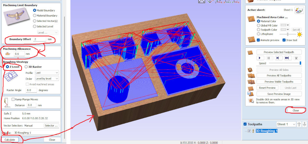
- setp 3: We proceeded in the same way as below to generate the finishing toolpaths. Once the toolpaths were generated we proceeded to their registration as indicated below.

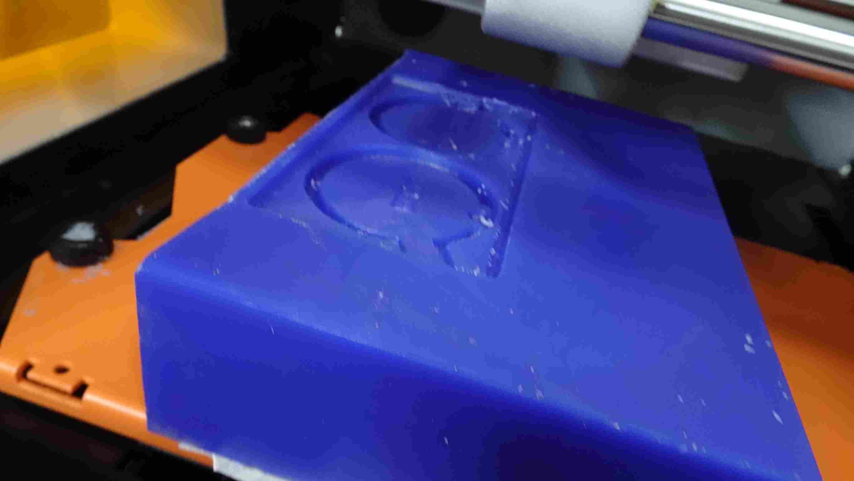
4. Milling Production
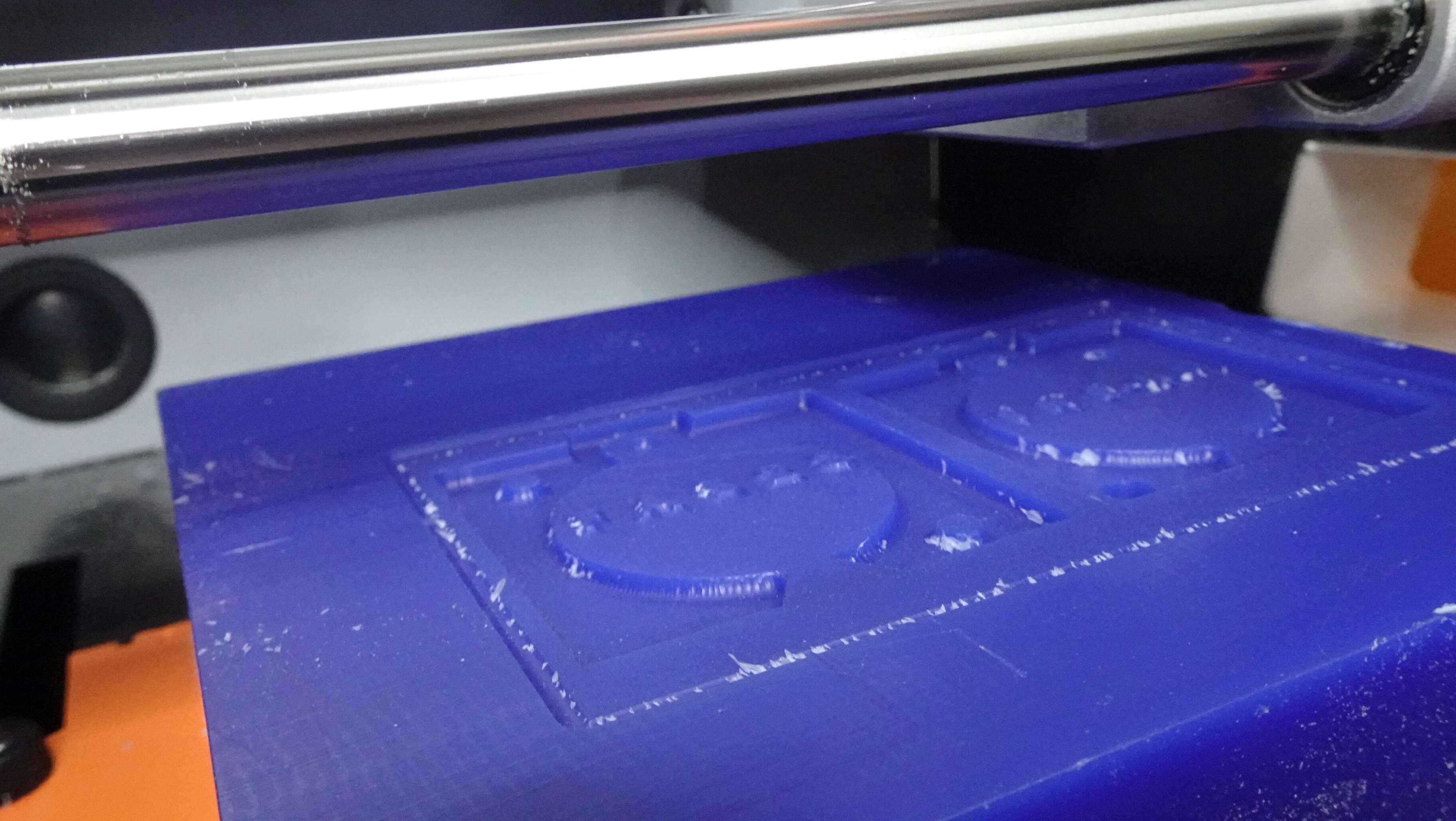
For the manufacture of the different parts of our mold we used a machinable wax as shown below with the Roland SRM-20 and the 1/8” cutter
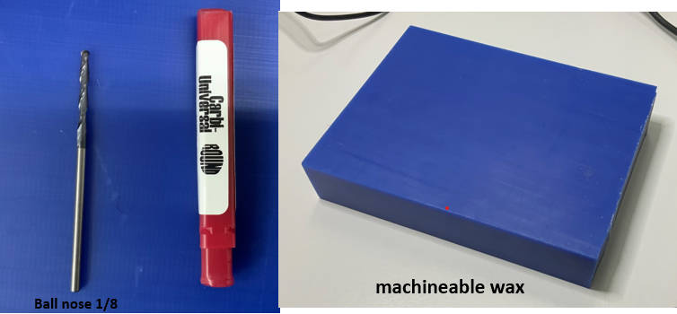
we’ll be using :
- a digital milling machine ;
- a milling cutter with a diameter of ;
- a wax plate
- double-sided adhesive tape.
For the machining procedure with the Roland SMR20 milling machine see the page of Week 8 (Electronics production).
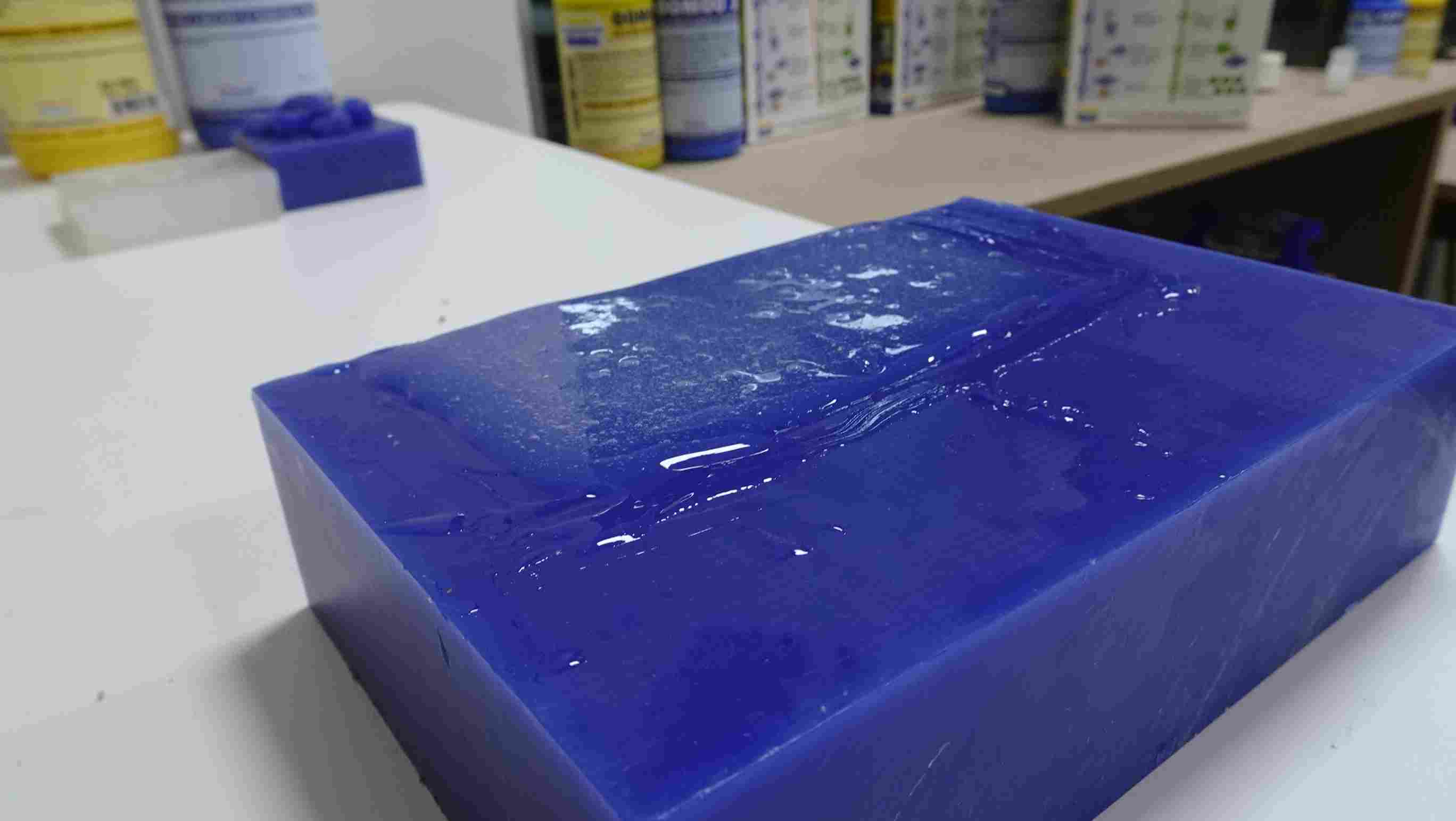
5. Realization of negative molds
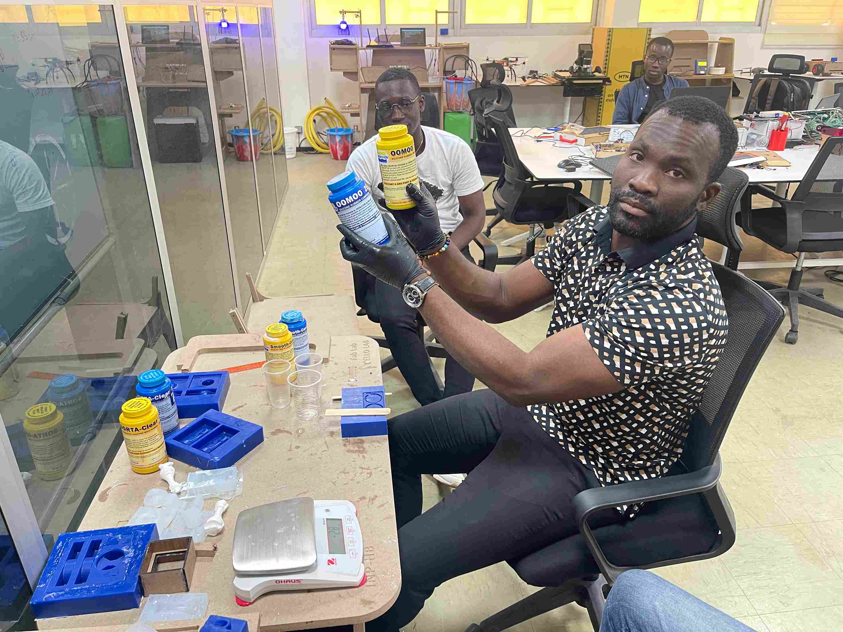
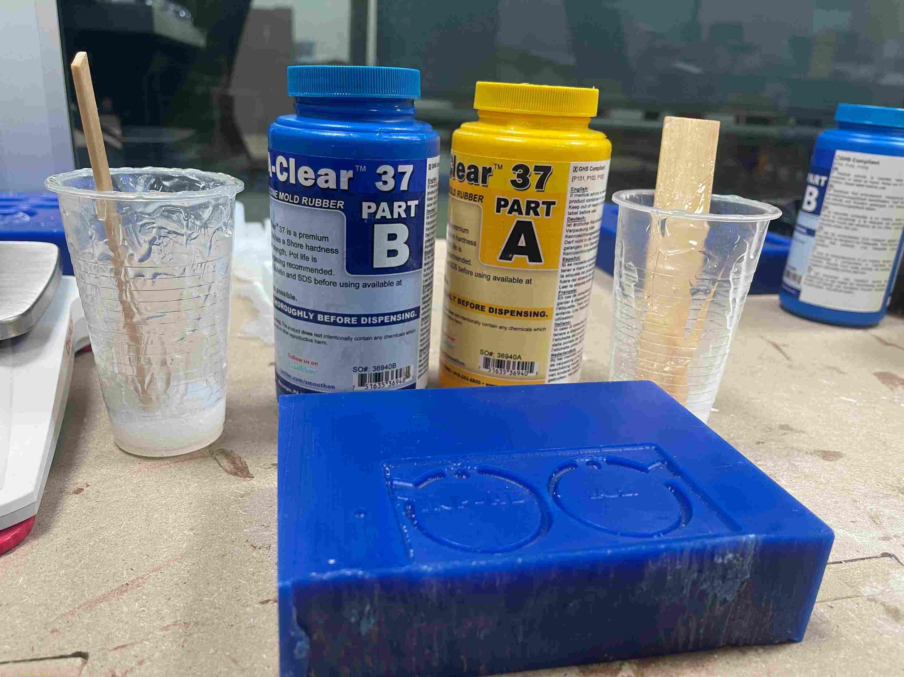
For the production of the negative molds we used SORTA-Clear 37 silicone mold rubber.
Caution: chemical products for molding can be dangerous for your health, for this reason there are safety rules that must be respected. we have selected the most relevant ones for us for more details click here
Safety
- ** Keep out of reach of children **
- ** Use in a properly ventilated area (“room-size” ventilation). **
- ** Wear safety glasses, long sleeves and rubber gloves to minimize the risk of contamination. **
- ** Wear only vinyl gloves. Latex gloves will prevent the rubber from hardening. **
For the use of SORTA-Clear 37 silicone we have referred to the technical data sheet from which we have derived the essential information below.
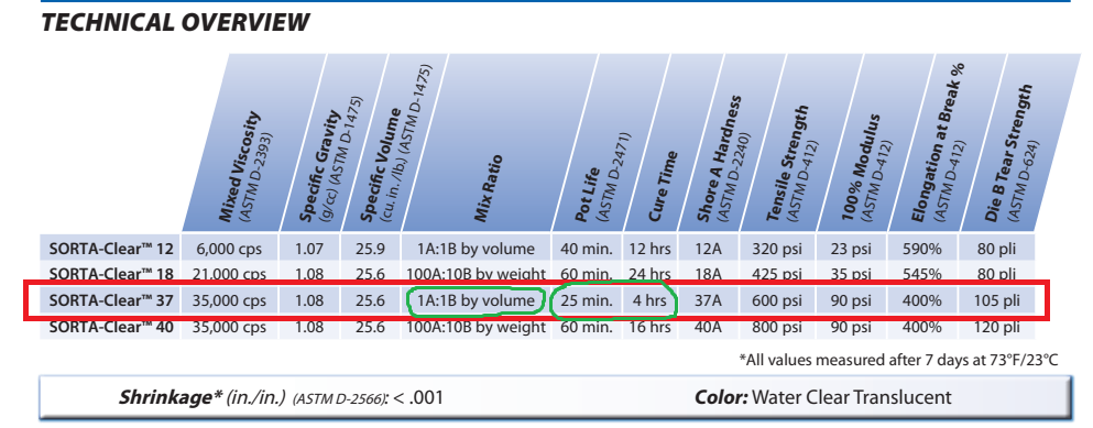
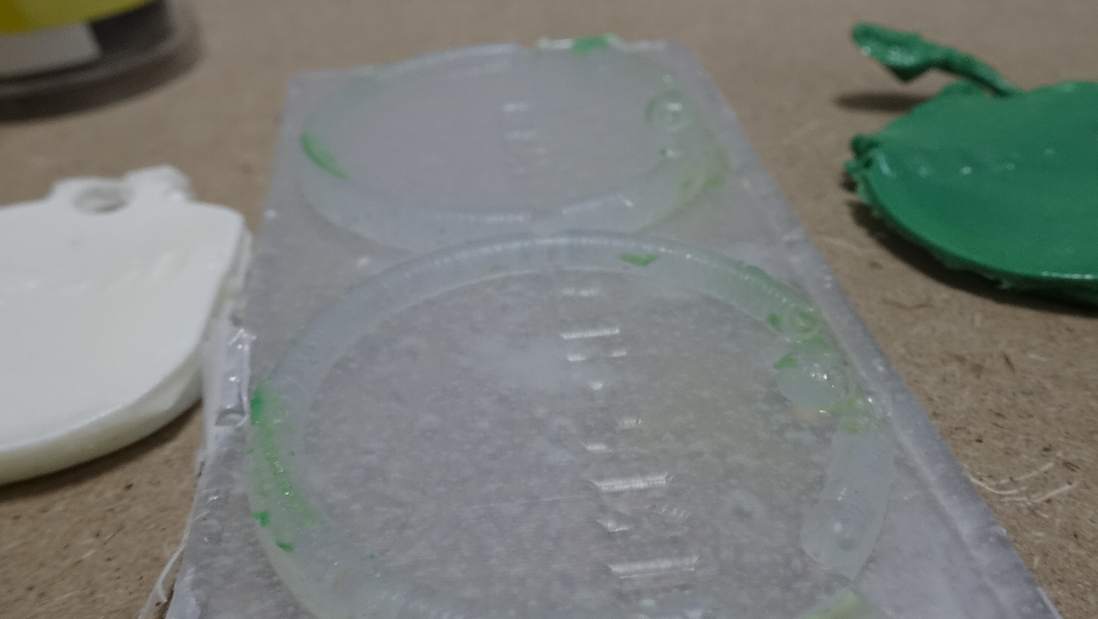
After following the instructions for mixing and pouring the SORTA-clear 37 silicone we obtained the following results.
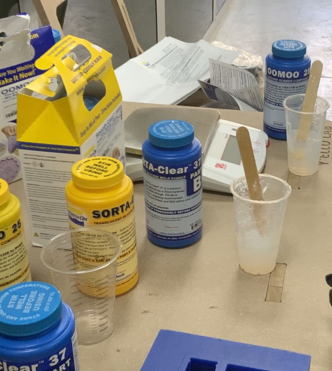
According to the manufacturer, it is essential to use the same quantity of product for A and B.
6. Realization of positive molds
For the realization of the positive molds, we used Smooth-cast 300 Series.
For the use of Smooth-cast 300 Series we have referred to the technical data sheet from which we have derived the essential information below.

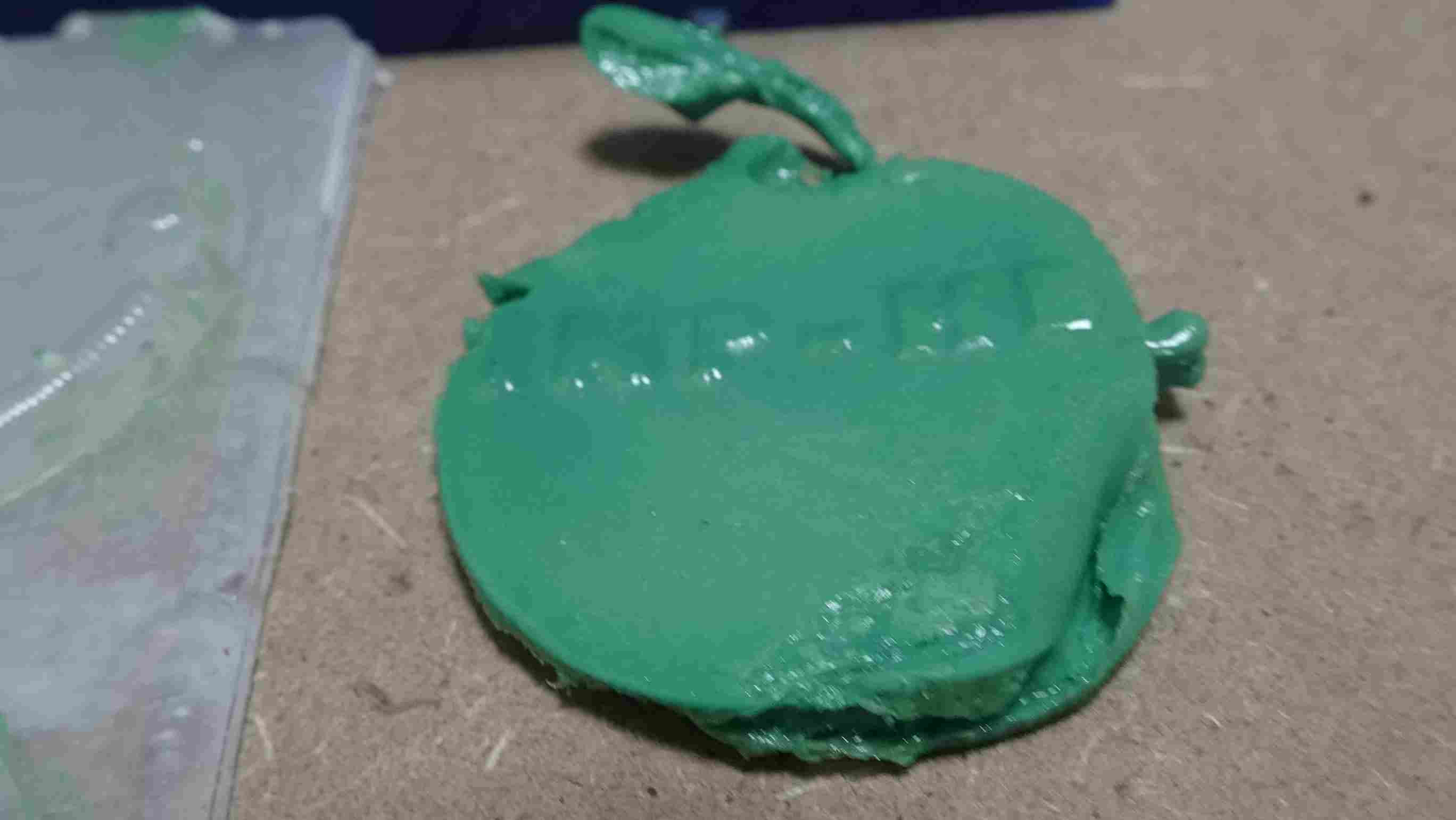
After following the instructions for mixing and pouring the Smooth-cast 300 Series we obtained the following results.

I wanted to test the colors on my molded part.
I use these dyes


Molded parts.
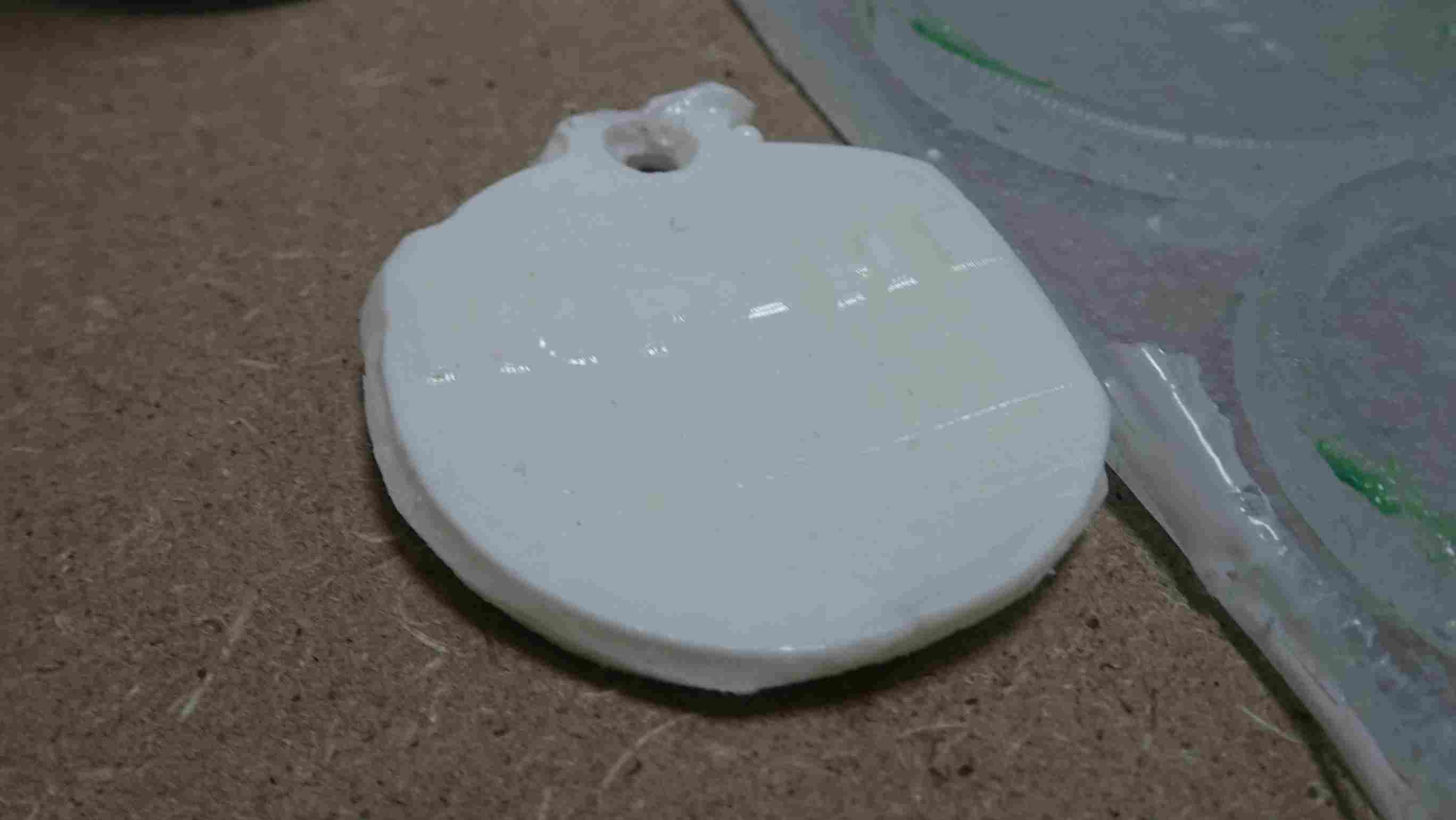
- I have encountered problems with this so I am proposing other solutions for improvement.
7. Error correction
For this first phase I missed my mold so my part didn’t have a good shape so I decided to make another mold correcting my mistakes I have to correct the :
- the junction of the two parts of the mold
- the depth of the writing
- the casting space
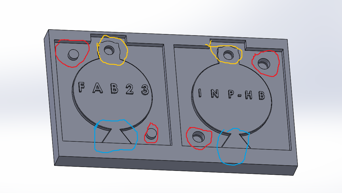
        - circled in red, is for the junction.
        - circled in blue is for the flow
        - circled in orange is for the key ring hole.
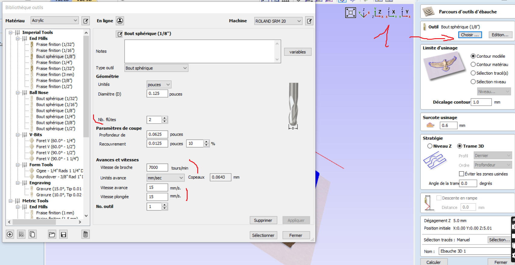
i made the thing for this mold

this is my toll parameters
- Explaination Video