07. Computer controlled machining
Part one : Assignments
1. Group assignment:
- Complete your lab’s safety training .
- Test runout, alignment, fixturing, speeds, feeds, materials and toolpaths for your machine.
- Document your work to the group work page and reflect on your individual page what you learned
2. Individual assignment:
- Make (design+mill+assemble) something big.
3. Task
-
Linked to the group assignment page.
-
Document how you designed your project(something big)
- Documented how you made your CAM-toolpath.
- Documented how you made someting BIG(setting up the machine).
- Described problems and how you fixed them.
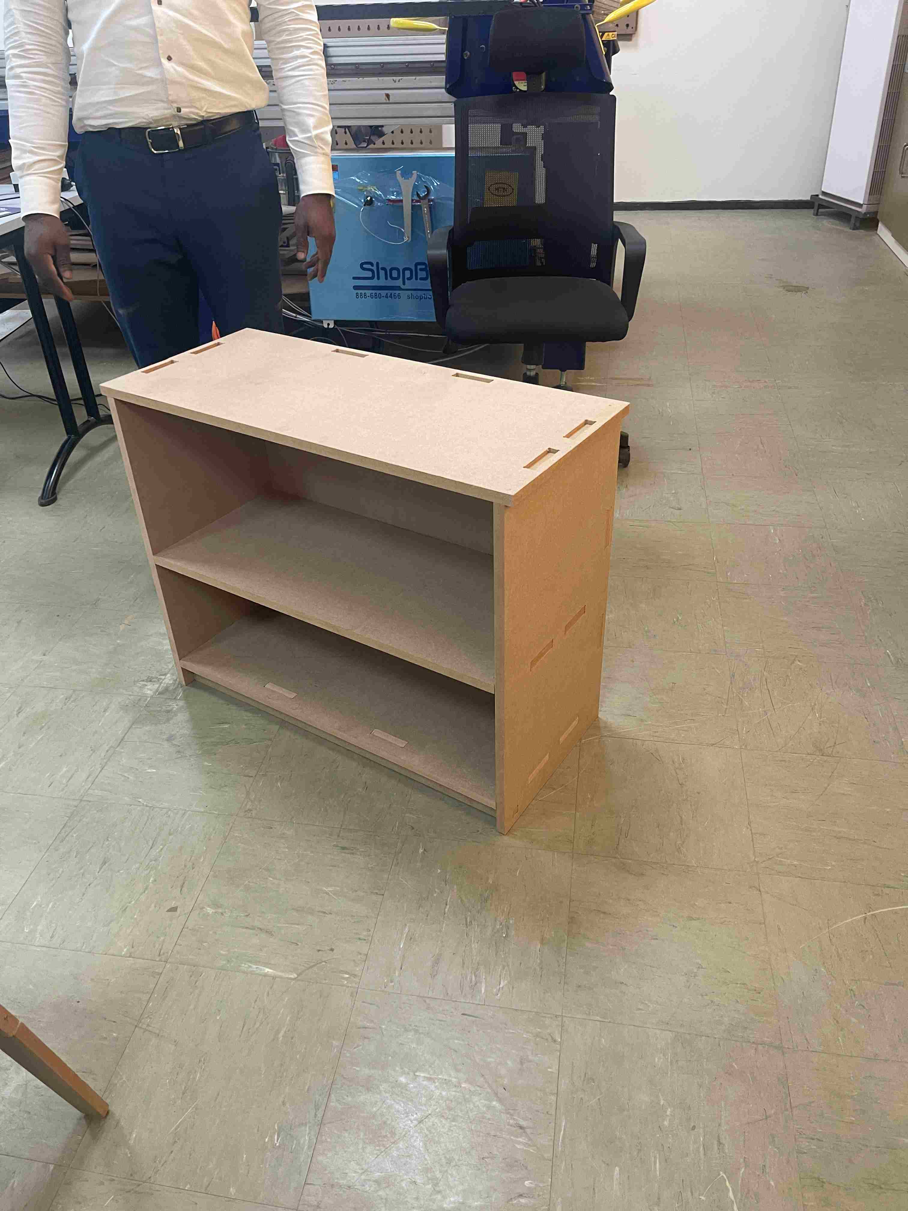
- Included your design files and ‘hero shot’ of your final product.
Part two : What I did
1. Groupe assignment
To see our group assignment click here
2. Individual project
-
overview 1.1. What is Computer controlled machining Computer Aided Manufacturing (CAM) is the use of software and computer-controlled machinery to automate a manufacturing process. Based on that definition, you need three components for a CAM system to function: Software that tells a machine how to make a product by generating toolpaths
1.2. Software
- FUSION 360
- SOLIDWORKS
- SOLIDEDGE
1.3. Machine and tools MACHINE
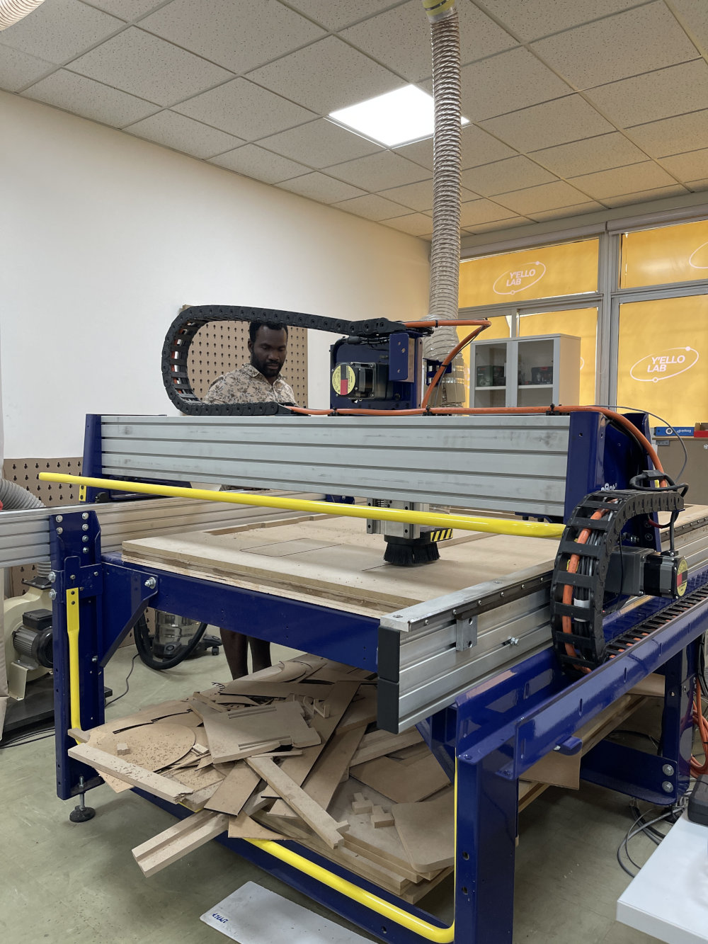 [shopbot] (https://design-milk.com/shopbot-brings-cnc-machines-to-your-garage-or-your-desk/)
TOOL 1/8” Downcut End Mill
1.4. material the material used is MDF MDF
-
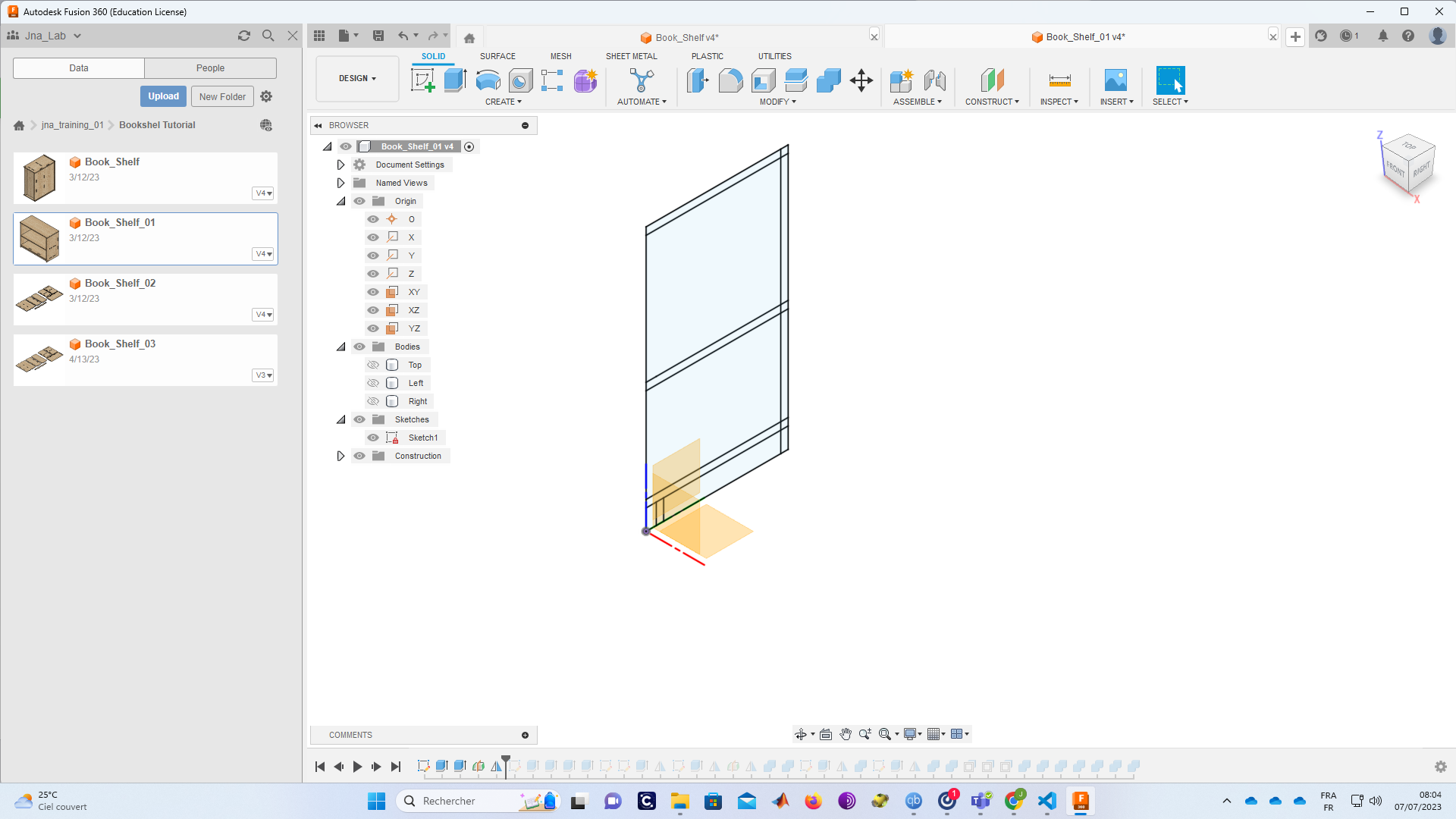
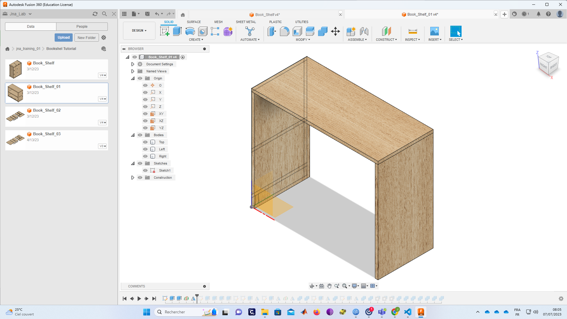
Design
2.1. Fusion 360
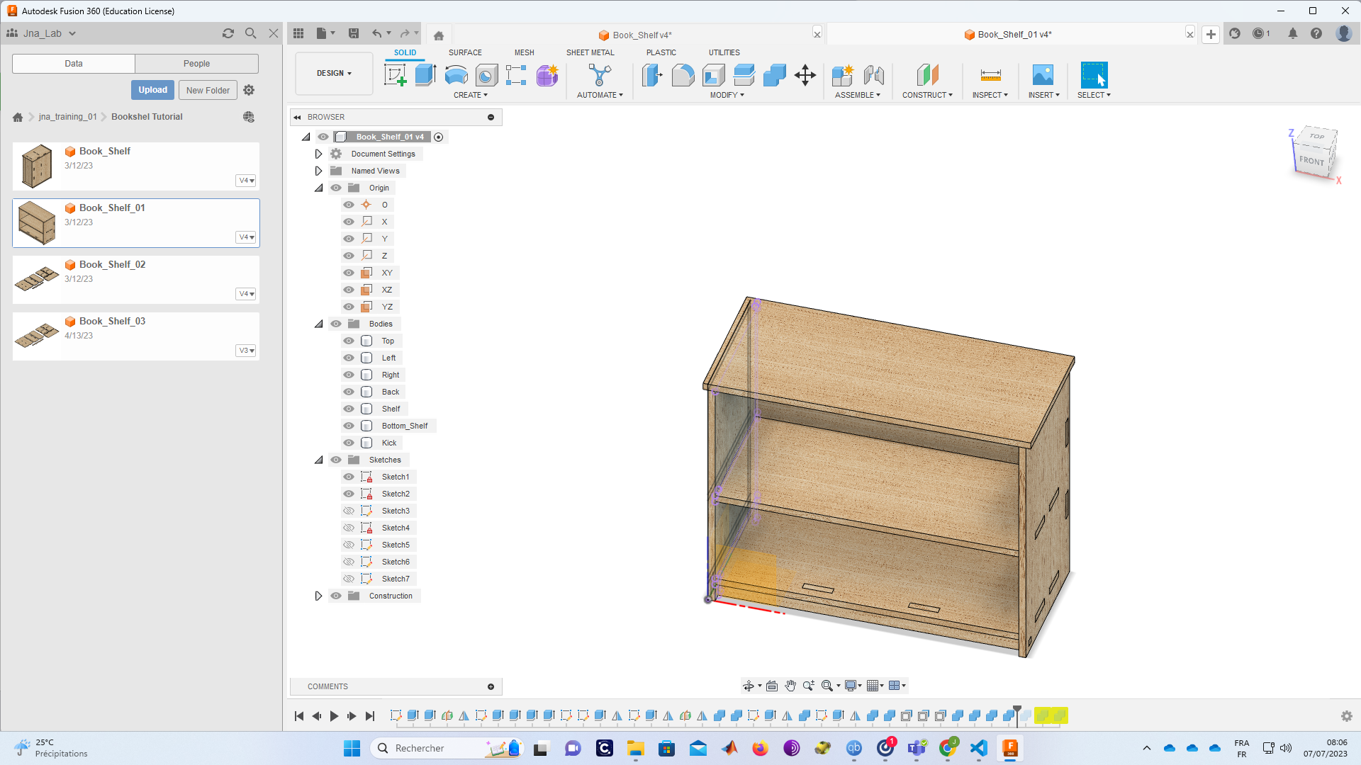
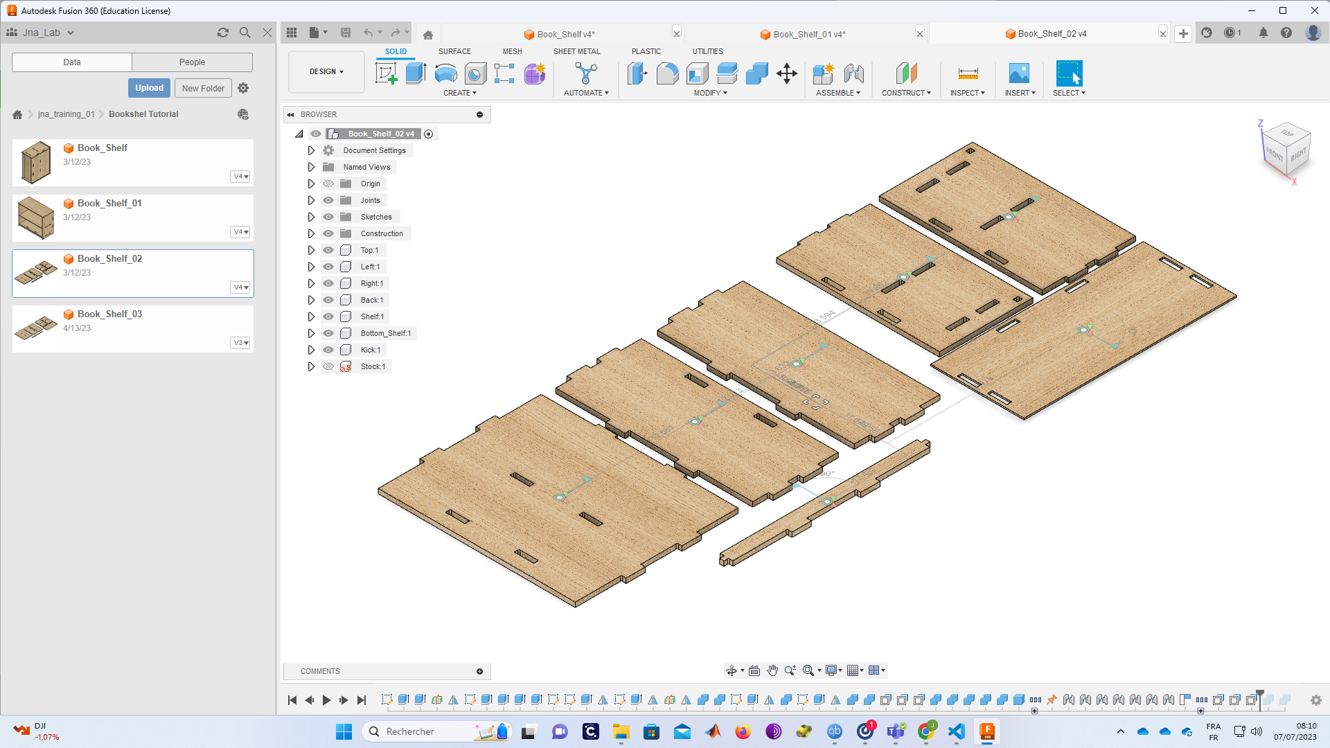
I exported the file in dxf poula format FAO su V carve Pr
-
Tools path We will in this part of our work generate toolpaths. we will use Vcarve software.
3.1. V-carve
Vacarev is a softare that is used to generate toolpath and disign. in my case i use it to only generate the toolpath, step - you can open the software and put the DXF inside on the v carve workspace.
-
you can also improt dxf file ( go to fil and clic on import )
-
an other way you can open dxf file with it (right cli on the fil and do open whith and select V carve )
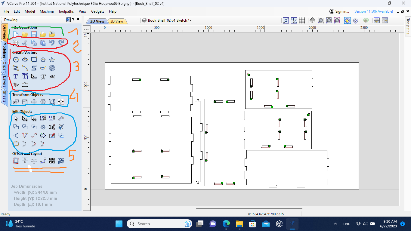 explain :
1 : WORKSPACE AND MATERIAL
2 : DESIGN TOOL
3 : TRANSFORM TOOL
4 : PAR SETTING
make sure that you parts are correct puted in the macine work sapce * the Machine workspace and the thickness should be selected before countinous
explaination :
1 : TYPE OFF toolpath (traces, profil…)
2 : -3D manunifacturing mode
3 : tool
4 : G code and simulation
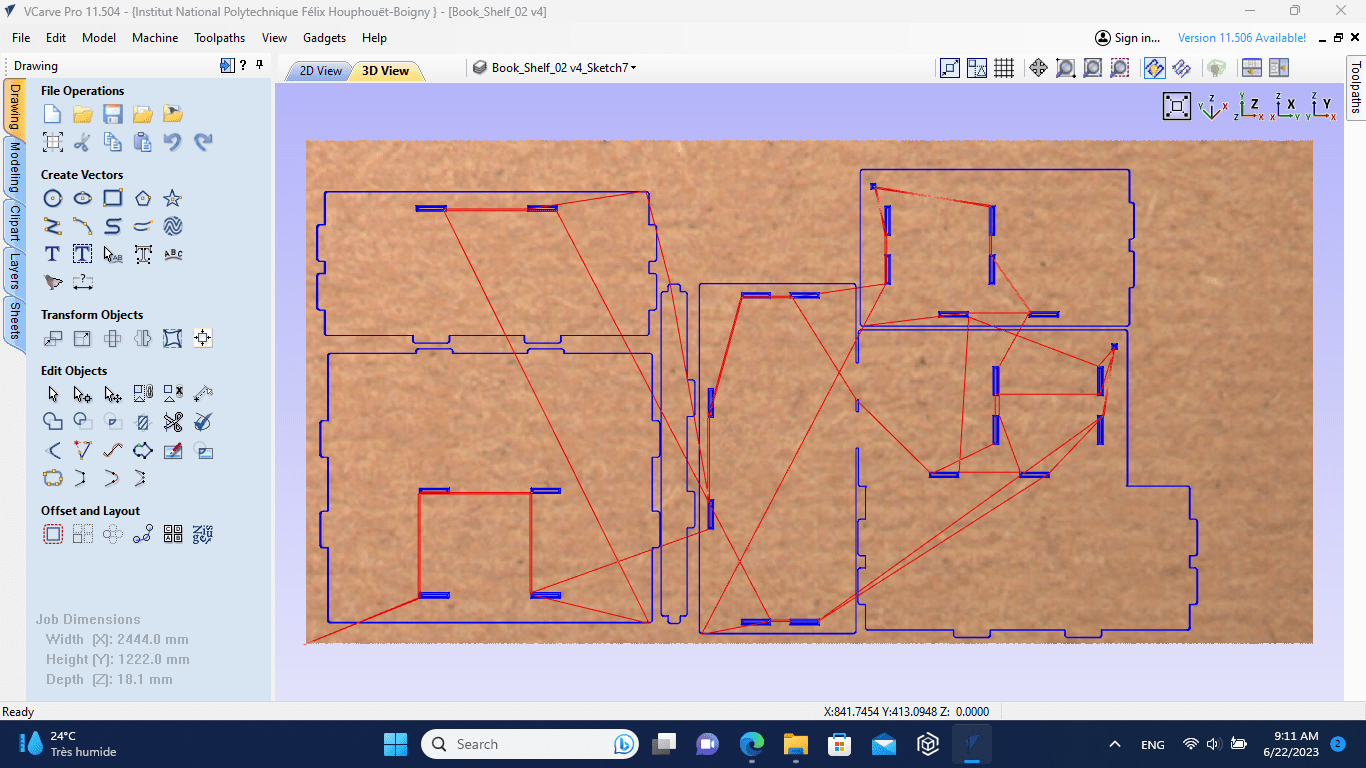
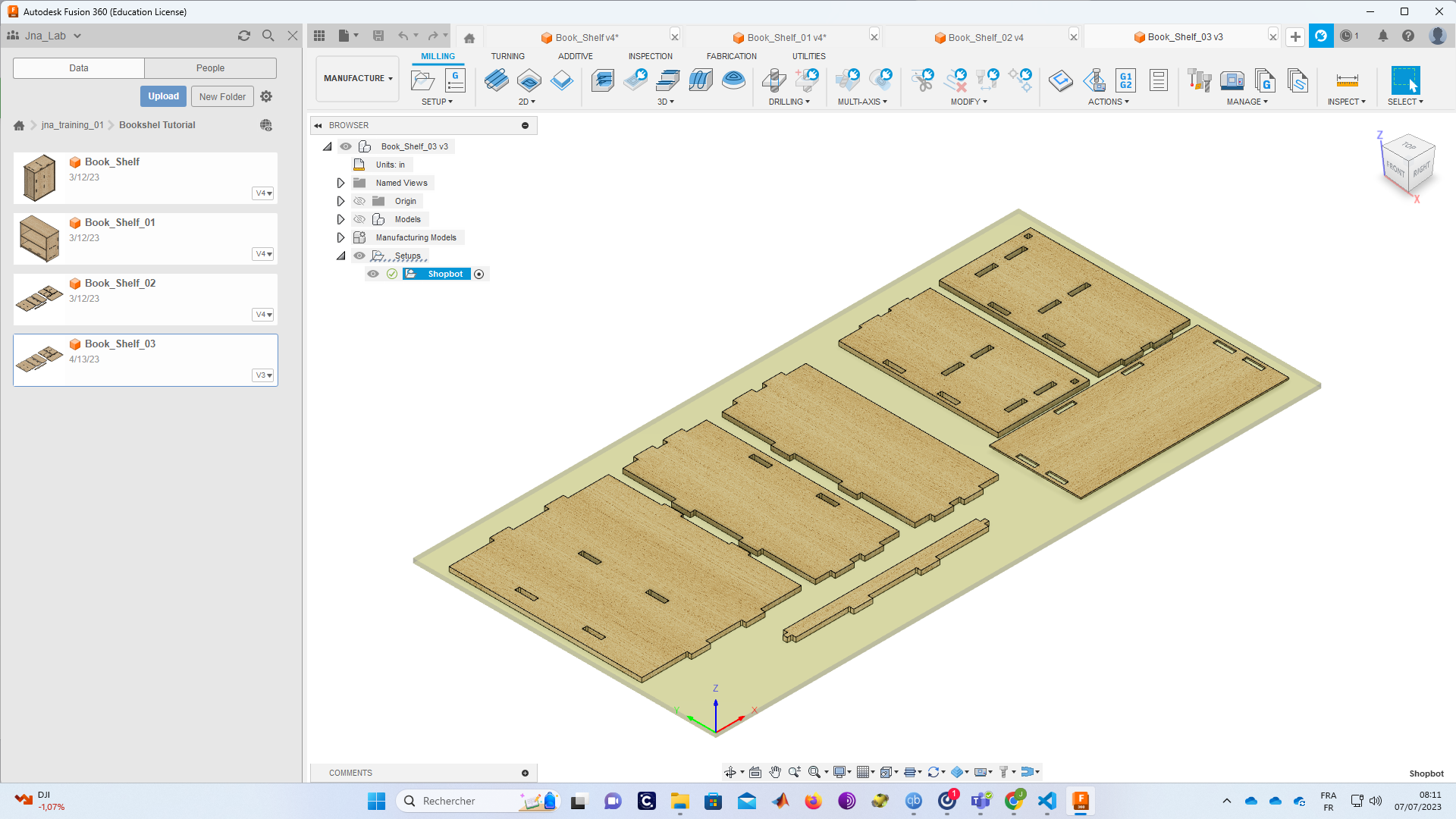
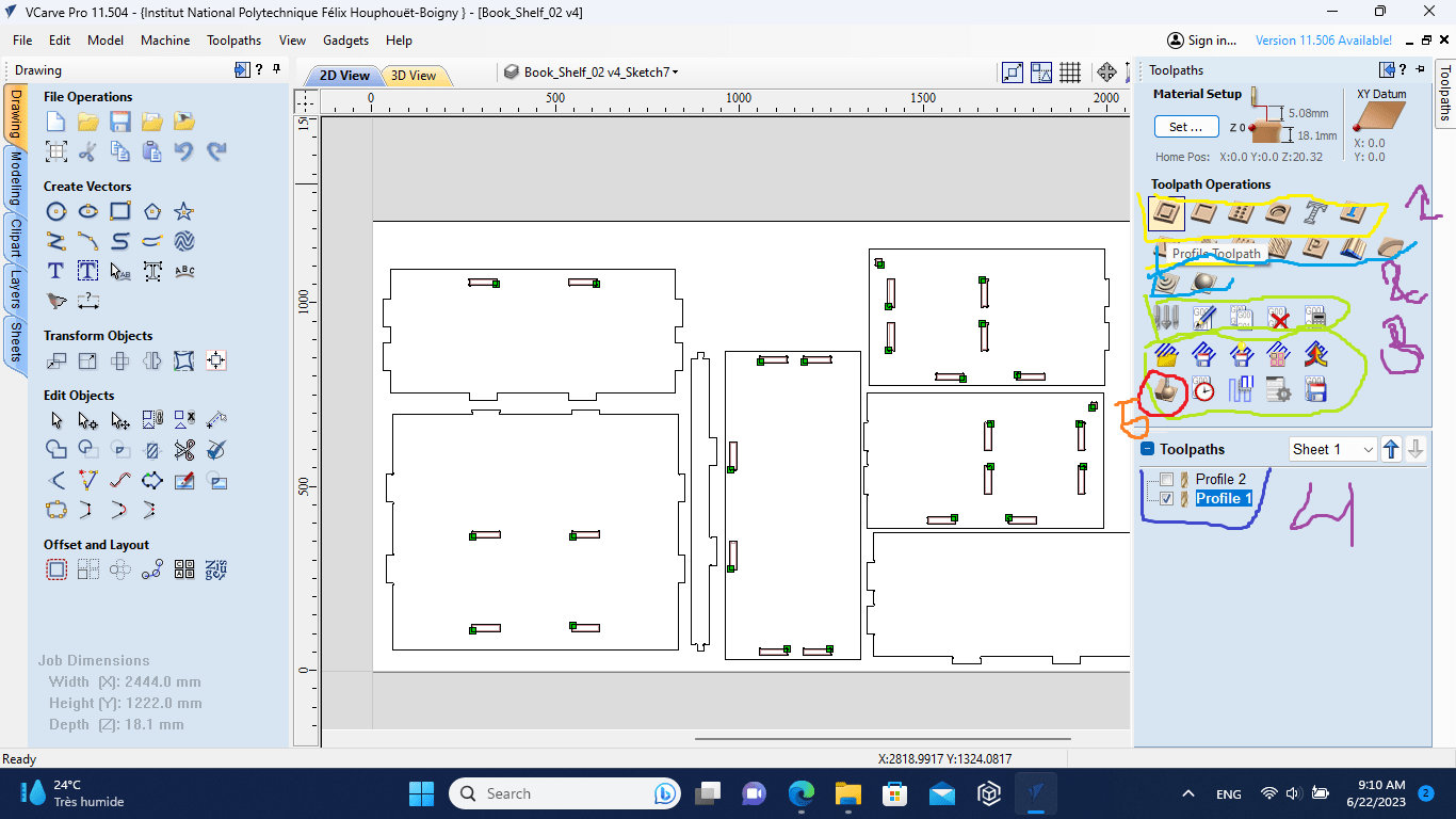
After finishing positioning the parts to be cut we will now move on to the generation of toolpaths. to go to the shopbot.
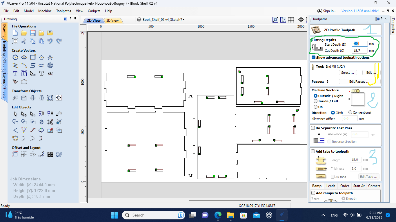
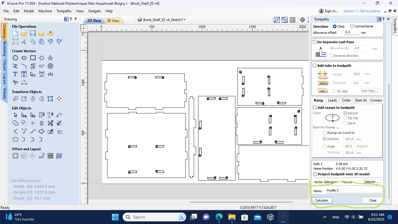
explaination :
1- Cutting depths and tool select and edit (1/8”)
2- Inside or outside ( it depend on what you want)
3- Material fixing
4 -tool path name of calculation
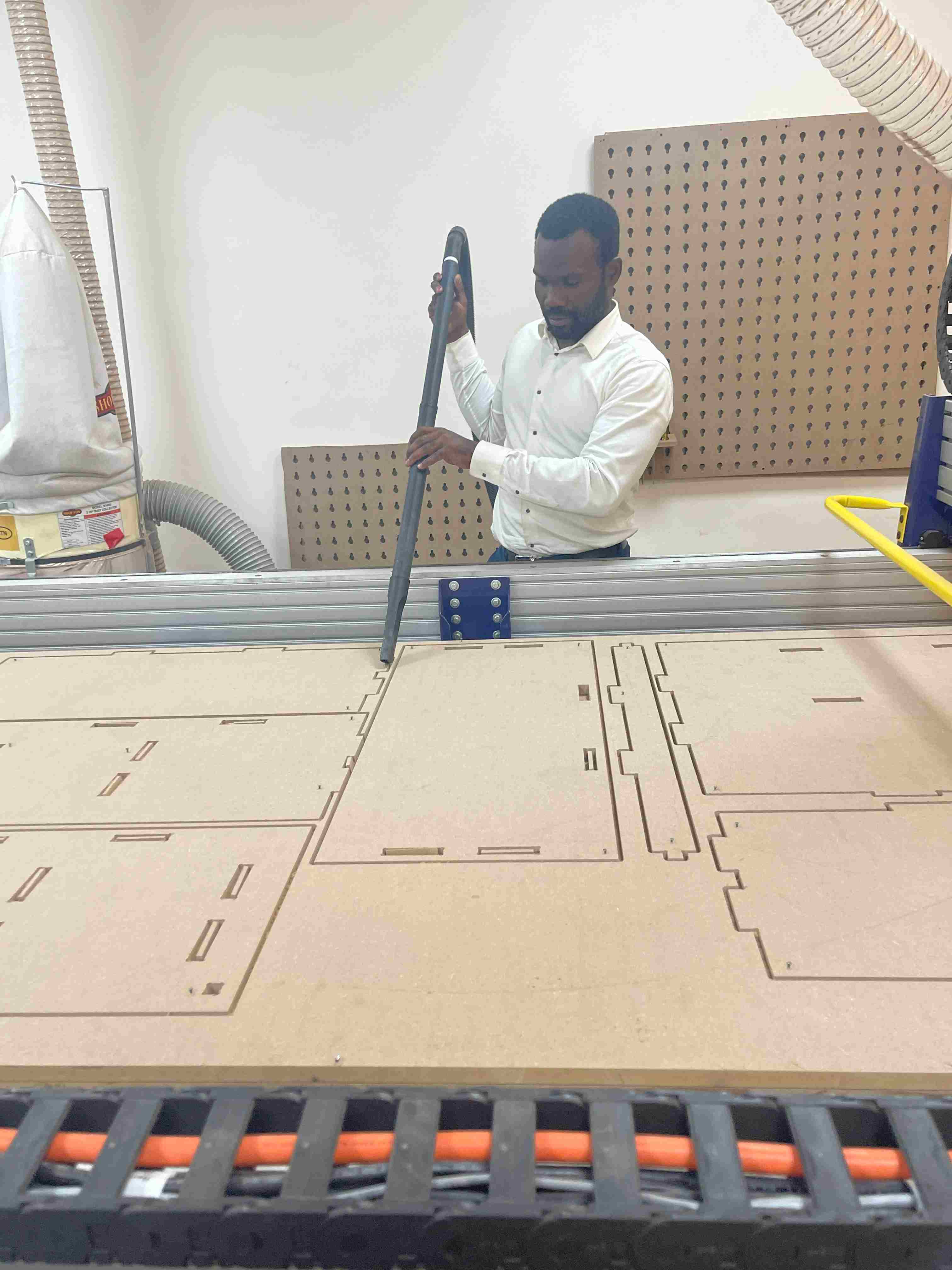
- Milling
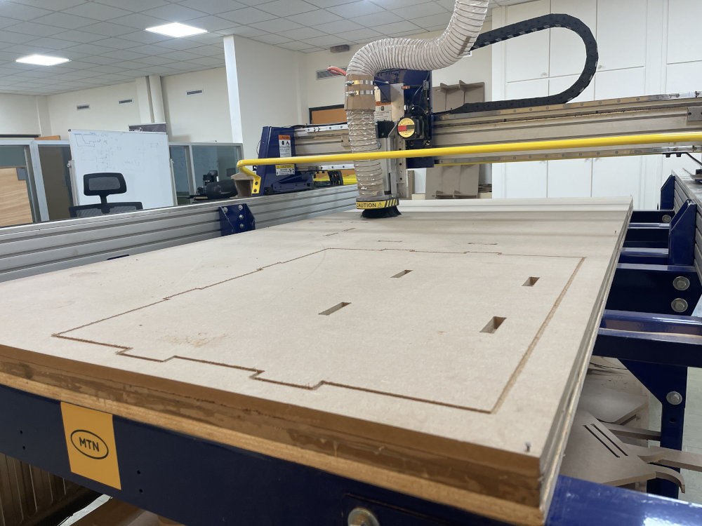
4.1. SDafety
4.2. **Milling**
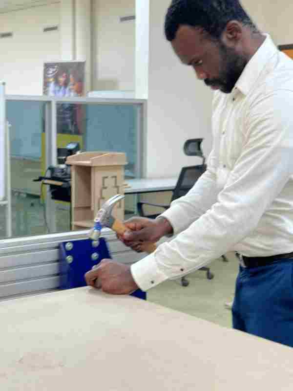
- Assembling
- file