08. Electronics Production
Part one : Assignments
1. Group assignment:
-
Characterize the design rules for your in-house PCB production process: document feeds, speeds, plunge rate, depth of cut (traces and outline) and tooling.
-
Document your work to the group work page and reflect on your individual page what you learned.
2. Individual assignment:
- Make and test the development board that you designed to interact and communicate with an embedded microcontroller.
Part two : What I did
Group assignment:
To see our group assignment click here
Individual assignment: I design final Projet boards
For this week i will product the electronic part of my fianl projet. We used the Roland SRM-20 milling machine available in our Fab Lab. For more details on electronic circuit design, please refer to the Week 6 web page (Electronic design).

how I did it:
1. Generation of the tool path
For the generation of toolpaths we have several solutions at our disposal: the use of Vcarve, FlatCAM, mods CE …
In choosing our solution, we chose V-carve because it gives us greater flexibility in the generation of toolpaths and complete modification of the parameters of the tools we have in our Fab Lab.
2. Fabrication
Before we start making our circuit we must first generate the toolpaths for the traces and contours of our circuit. To do this we will use two tools namely : a flat end mill of diameter 1/64 inch for the traces of our circuit and a flat end mill of diameter 1/32 inch for the contour of our circuit.

For a better understanding of the machining procedure of the circuit we have broken it down into several steps namely :
Step 1: Preparation of the machine
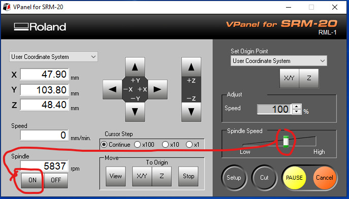
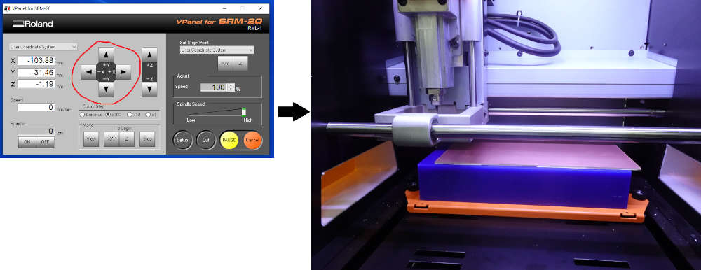
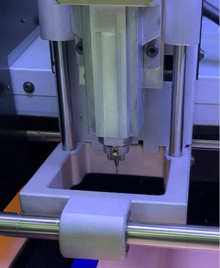
- Turn on the Roland SRM-20 milling machine, connect it to your computer, and open the VPanel software for SRM-20. A good tip is to warm up the spindle for 10 minutes at half speed before using it. To do this, move the gauge in the “Spindle Spend” module to the middle as shown below, click on “ON” in “Spindle” and wait 10 minutes.
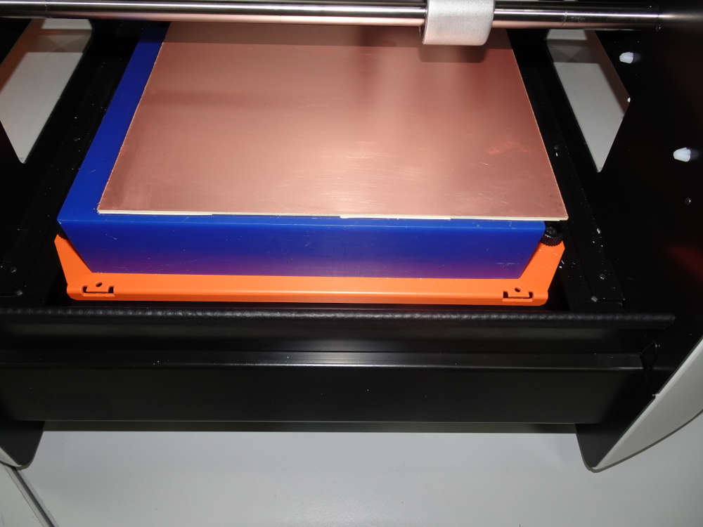
- After the 10 minutes click on “OFF”, now we go to the assembly of the circuit board as shown below.
- Since we start by machining the traces of our circuit we will mount the end mill 1/64 inch.
Be careful that the tool doesn’t fall off or it will break and that will be a shame.
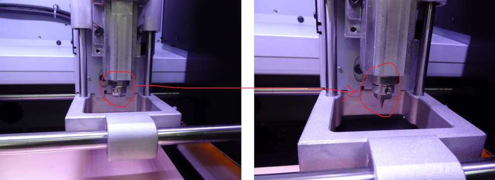
Once the tool is mounted, we move on to the definition of the X, Y and Z axis zero.
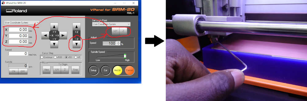
Step 2: Definition of the X, Y and Z axis zero.
- First we start with the X and Y axes. We use the buttons Y+; Y-; X+ and X- to move the X and Y axes to the original position we want.
Note that the (0,0) of the file we created with mods is in the lower left corner.
- For the origin of Z we click on the “Z-” button until we are close to the plate, then we click on the X/Y and Z buttons in the “Set Origin Point” area and we loosen the endmill so that it falls on the surface of the board and we tighten the endmill.
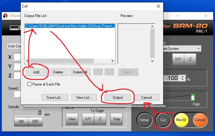
Step 3: Cutting out the circuit board traces
- to machine the circuit board traces, click on “cut” in Vpanel and select the trace file generated by mods as shown below and launch the machining by clicking on output.
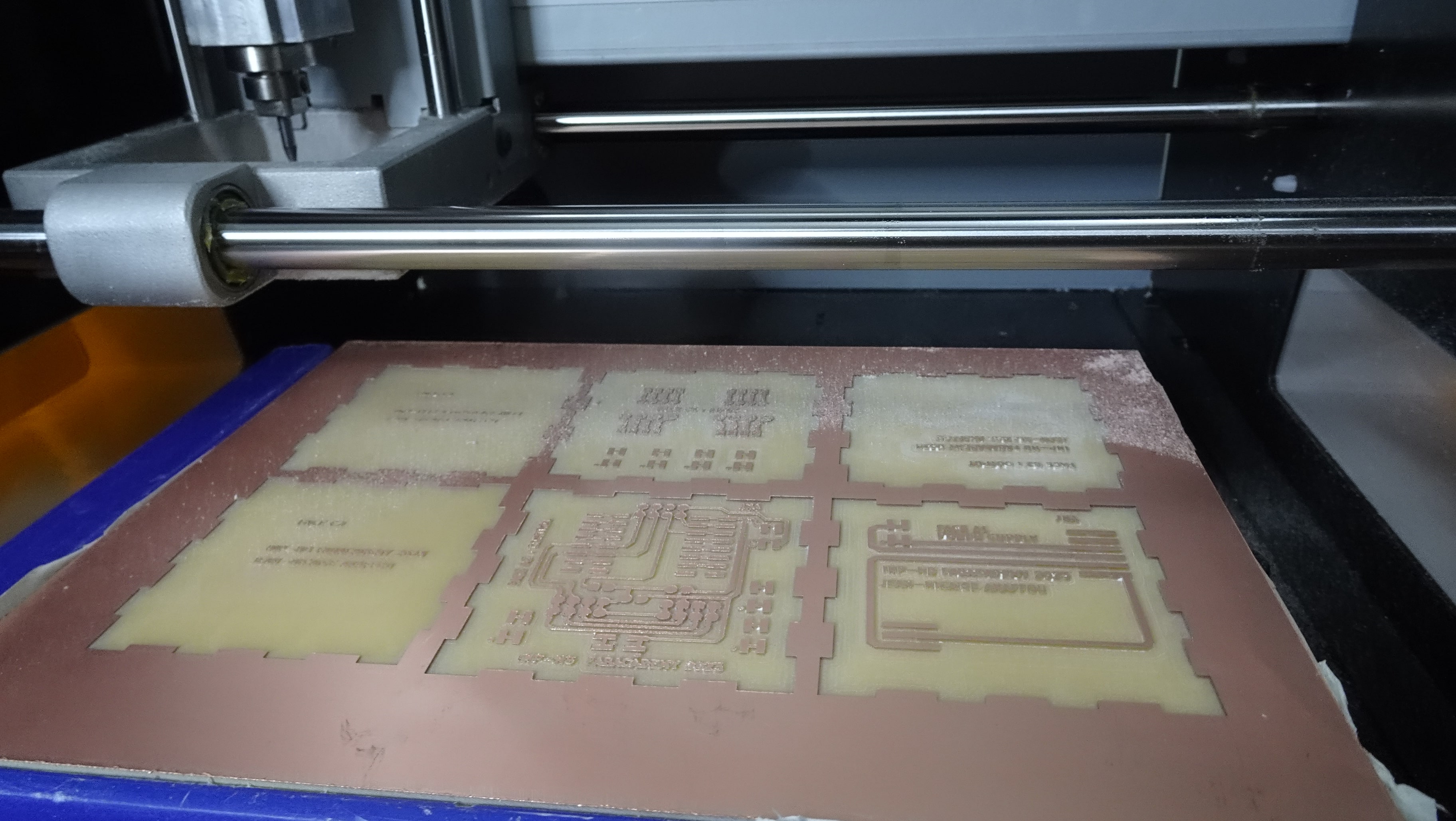
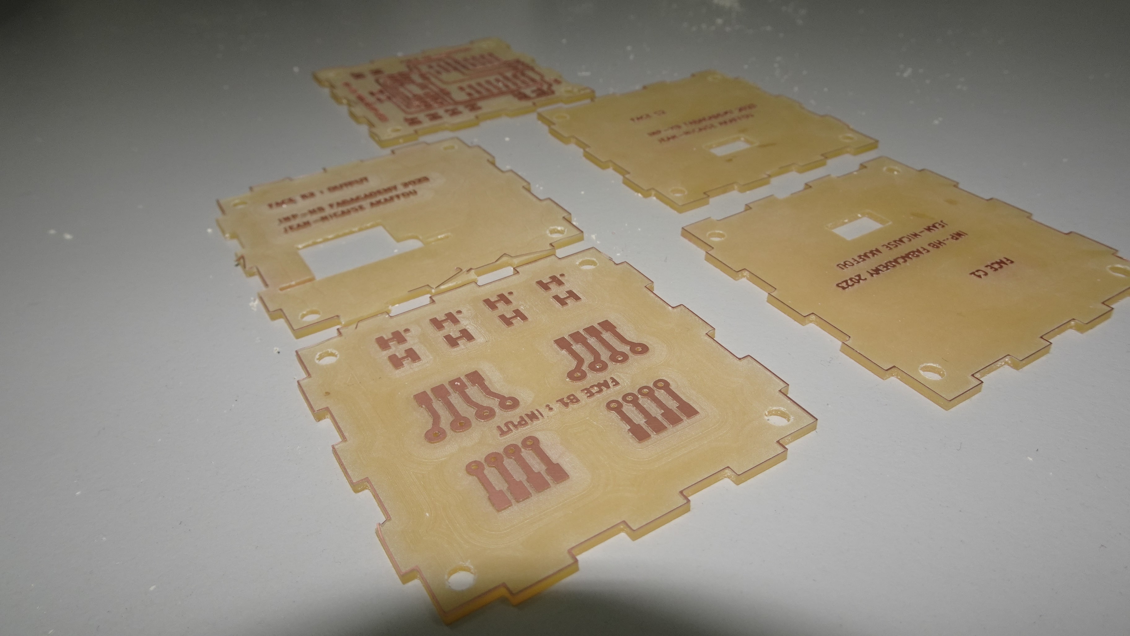
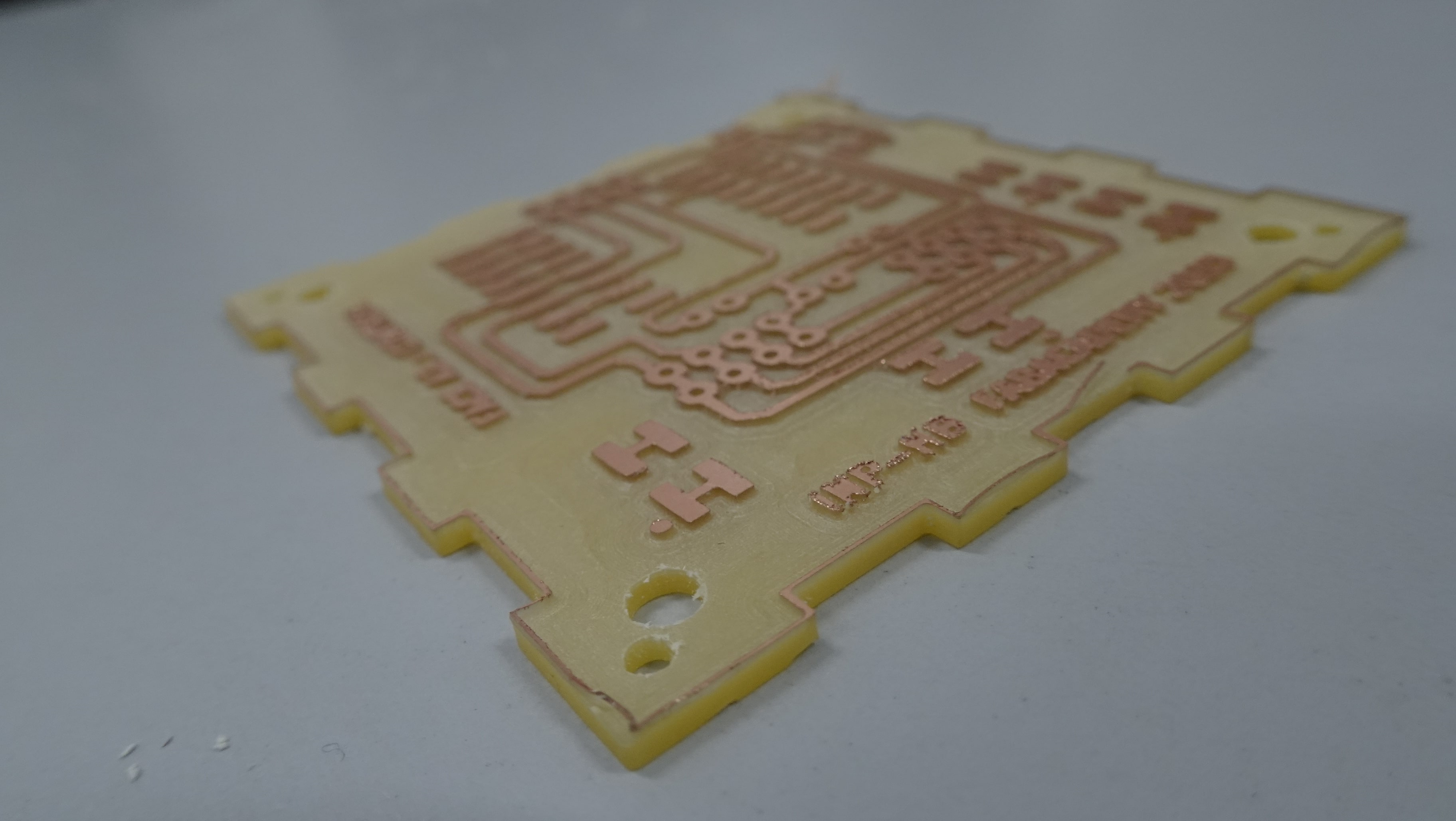
- We obtained the following results after 1h30mm of machining.
- Once the traces of the circuit board are finished we move on to the machining of the circuit board outline. To do this we change tools using endmill 1/32 inch. Once mounted we take the origin of the Z axis before starting the machining.
- After 25 minutes of machining we obtained the following results.
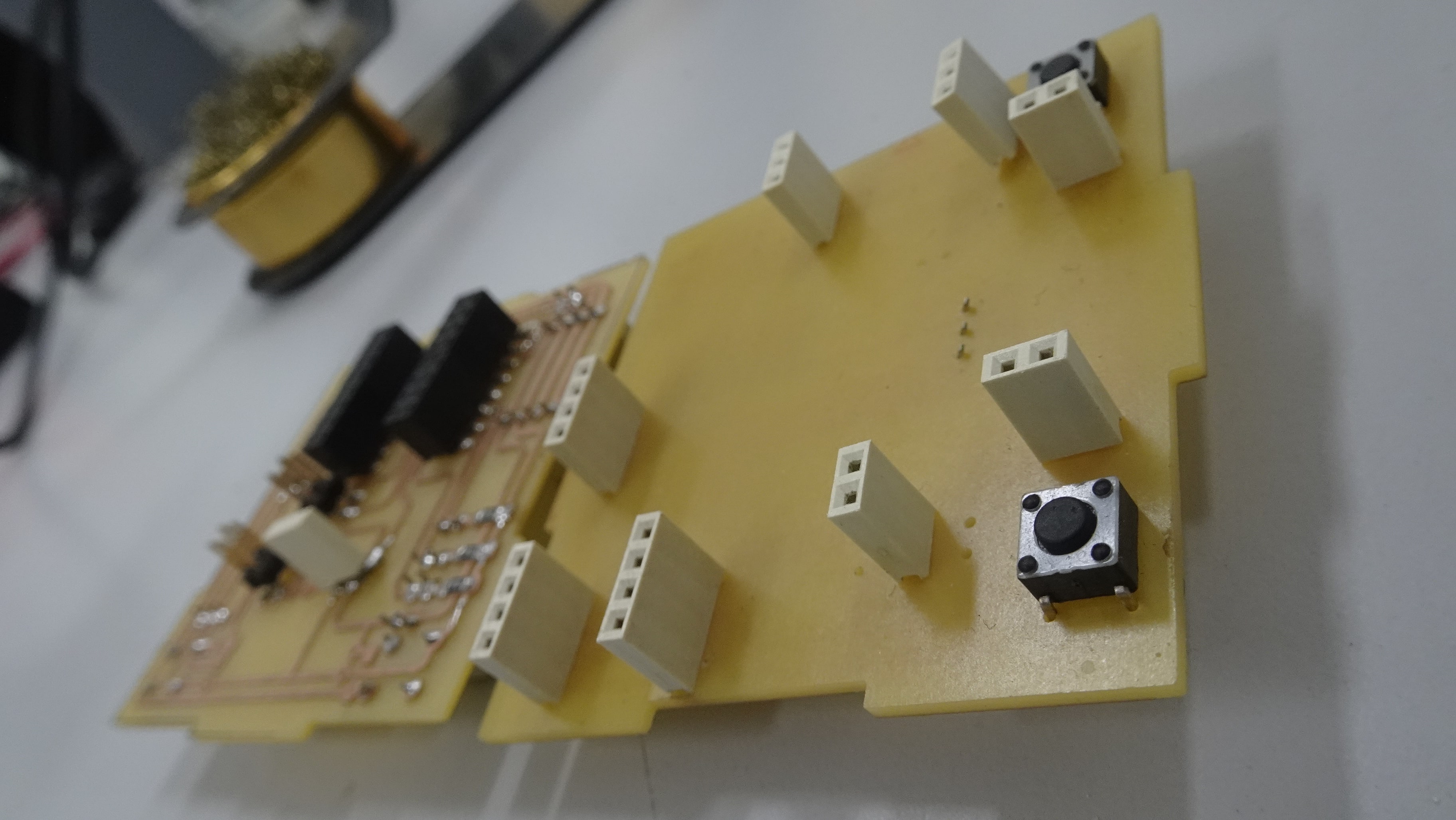
I soldered my components