03. Computer-controlled Cutting
Part one : Assignments
-
Groupe assignment
- Characterize your laser cutter’s focus, power, speed, rate, kerf, and joint clearance.
- Document your work to the group work page and reflect on your individual page what you learned.
-
Individual project
- Design, lasercut, and document a parametric press-fit construction kit, which can be assembled in multiple ways. Account for the laser cutter kerf.
- Cut something on the vinyl cutter.
-
Task
- Linked to the group assignment page
- Explained how you created your parametric design.
- Documented how you made your press-fit kit.
- Documented how you made something with the vinyl cutter.
- Included your original design files.
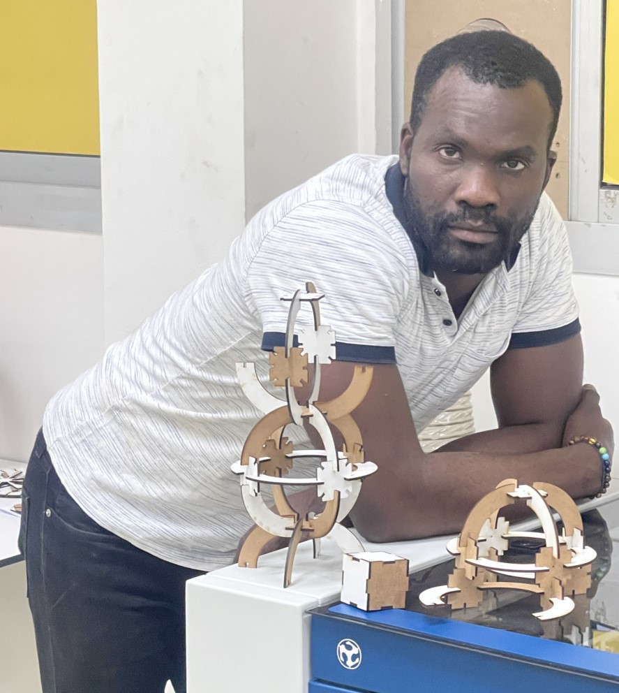
- Included hero shots of youur results
Part two : Groupe assignment
Part three : Individual project
1. What is computer controlled cutting
Computer controlled cutting is a computer controlled router related to the hand held router used for cutting various hard materials such as wood, composites, aluminium, steel, plastics and more.
1.1. Laser cutter
A laser cutter is a piece of technology which uses a laser to cut or engrave material based on computer controlled parameters. The powerful and highly accurate laser focuses on a small area of the material. The laser cutter can actually cut through different materials such as plastics, wood, rubbers, foam, fabrics, acrylic and more. When using the laser cutter you have total control over the power and speed of the laser. There are also several techniques which can be done using the laser cutter such as:
-
Laser marking: this involves the melting of a surface layer of a material to leave a mark behind.
-
Laser engraving: this is similar to laser marking, with the difference being that the aim here is to create a deep engraved mark.
-
Laser cutting: This is a process where material is cut, and this can be for small and fine materials or materials with a much greater level up resistance.
-
Laser drilling: This involves the creation of popped holes or dents into a material, which is achieved by pulsing a laser beam on a particular area repeatedly.
-
Laser welding: This is the process of welding materials together, wether this is one piece or multiple pieces of similar or dissimilar material.
2. Laser Cutter
2.1. My laser Cutting
2.1.1. Overview
Laser cutting is a technology that uses a laser to vaporize materials, resulting in a cut edge. While typically used for industrial manufacturing applications, it is now used by schools, small businesses, architecture, and hobbyists. Laser cutting works by directing the output of a high-power laser most commonly through optics. The laser optics and CNC (computer numerical control) are used to direct the laser beam to the material. Laser engraving is done with the same technology, but using reduced laser power. LASER stands for Light Amplification by Stimulated Emission of Radiation.
There are three main types of lasers:
-
CO2 lasers (most lasers on the market). Generally, the CO2 laser uses a gas mixture coupled with an electric discharge to produce the laser beam,
-
YAG (or Yttrium and Aluminum Garnet) lasers. The laser beam is produced by the excitation of a synthetic crystal by an electric discharge or a light source,
-
Fiber optic lasers (the latest development in laser cutting). The laser beam is generated in an active fiber and conveyed by means of a transport fiber to the cutting head of the machine.
2.2. Press-fit Kit
2.2.1. What is press fit?
A press fit, sometimes known as an interference fit, is a method of joining two tight-fitting parts that rely on friction. This is one of the most preferred fastening methods for applications that require a lasting bond and perfect alignment.
2.2.2. How a press fit works
To understand how press fit works, we first need to describe the physical characteristics of the two mating parts. For the basic example of a shaft and a hole, it is critical to realize that the hole is slightly smaller than the shaft.
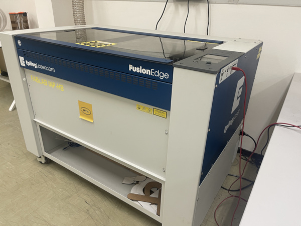
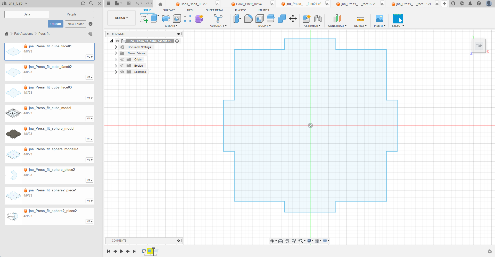
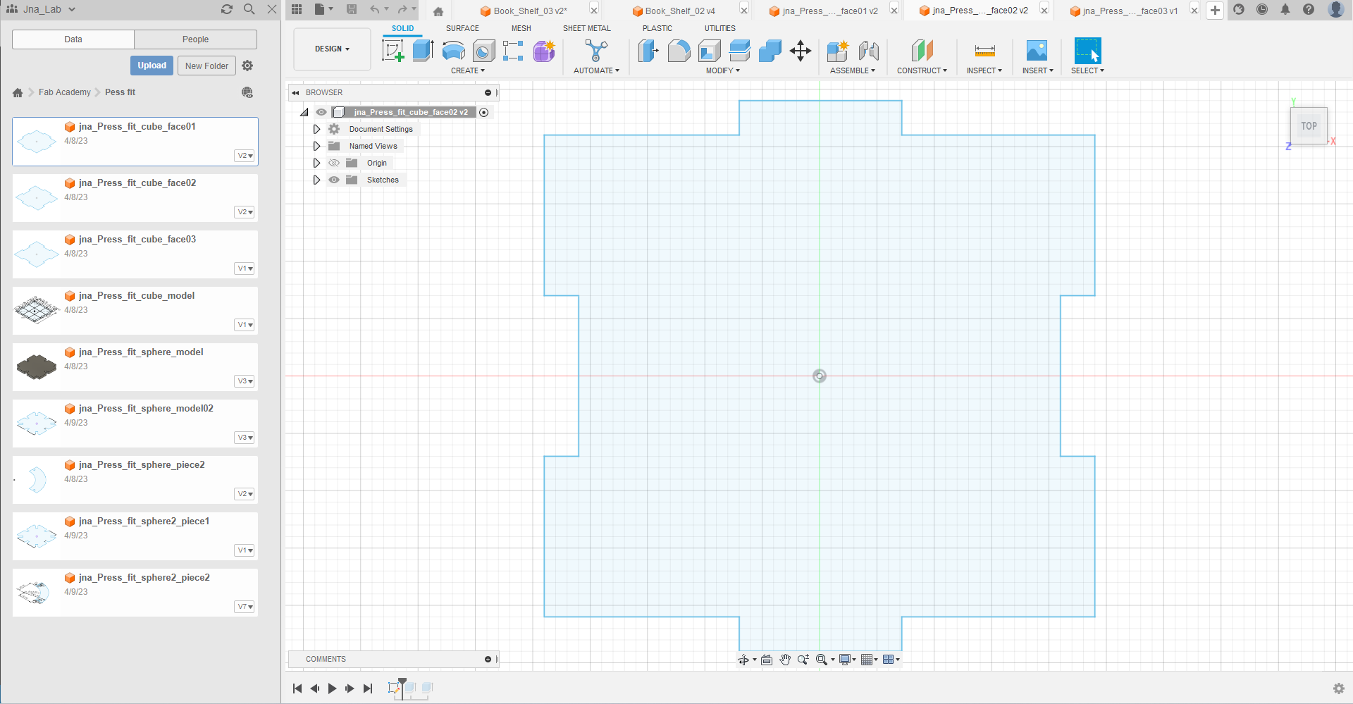
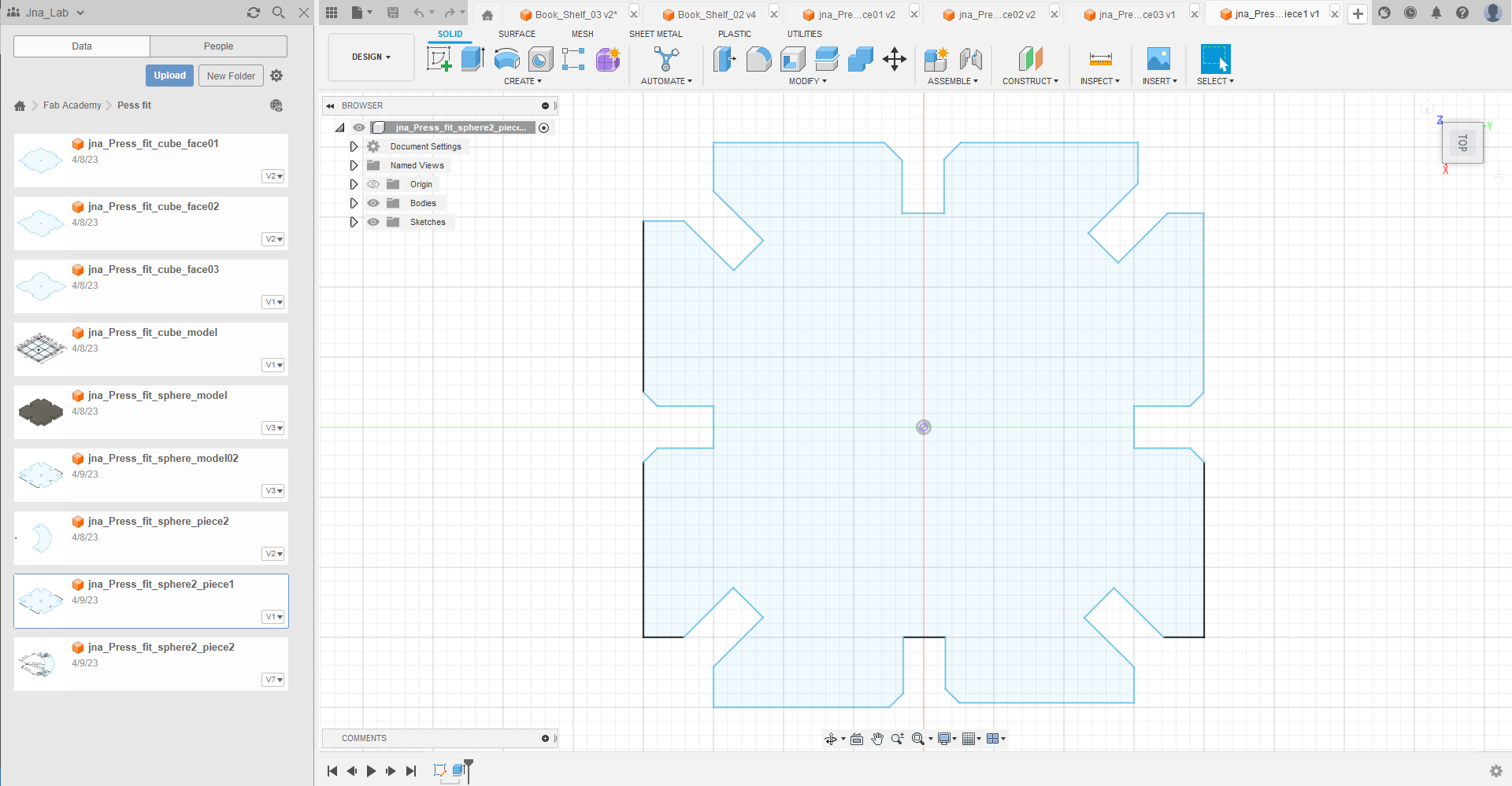
2.2.3. My cube
To make my cube, I followed these steps
step_01 : Draw the three faces of my cube with Autodesk Fusion 360
Step_02 : Export my files with the extension .dxf
Step_03 : Open Inkscape and import files
Step_04 : configure and set up Inkscape
Step_05 : Make the cut
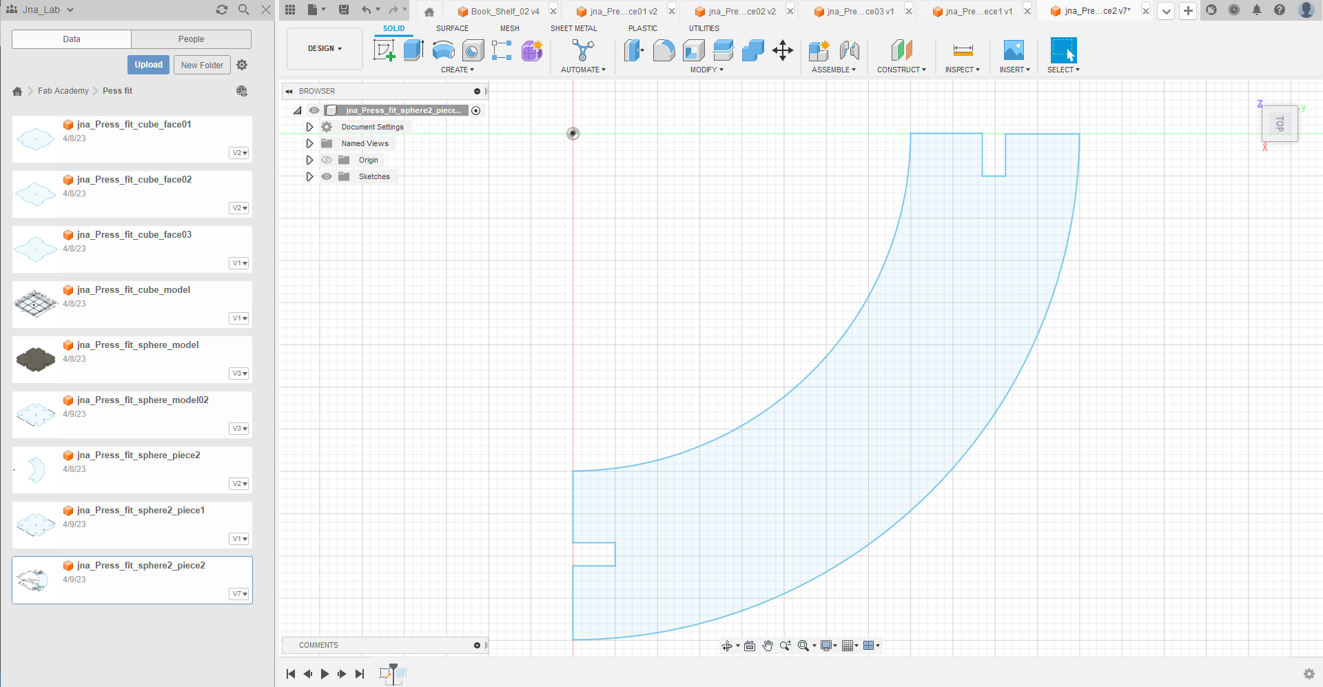
2.3.2. My little sphere
step_01 : Draw the two part of my sphere with Autodesk Fusion 360
Step_02 : Export my files with the extension .dxf
Step_03 : Open Inkscape and import files
Step_04 : configure and set up Inkscape
Step_05 : Make the cut
Step_05 : My press fit
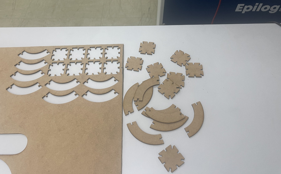
2.4. Conclusion
When assembling our press-fit kit, we didn’t encounter any particular problems. The parts fitted together correctly. We can therefore conclude that the cutting parameters and parametric design we have chosen below are sound.
Summary of press-fit kit cutting parameters
| Parameters | Value |
|---|---|
| Materials | MDF |
| Process Type | Vector |
| Speed | 15 % |
| Power | 30 % |
| Frequency | 100 % |
| Cycles | 1 |
| Auto Focus | Off |
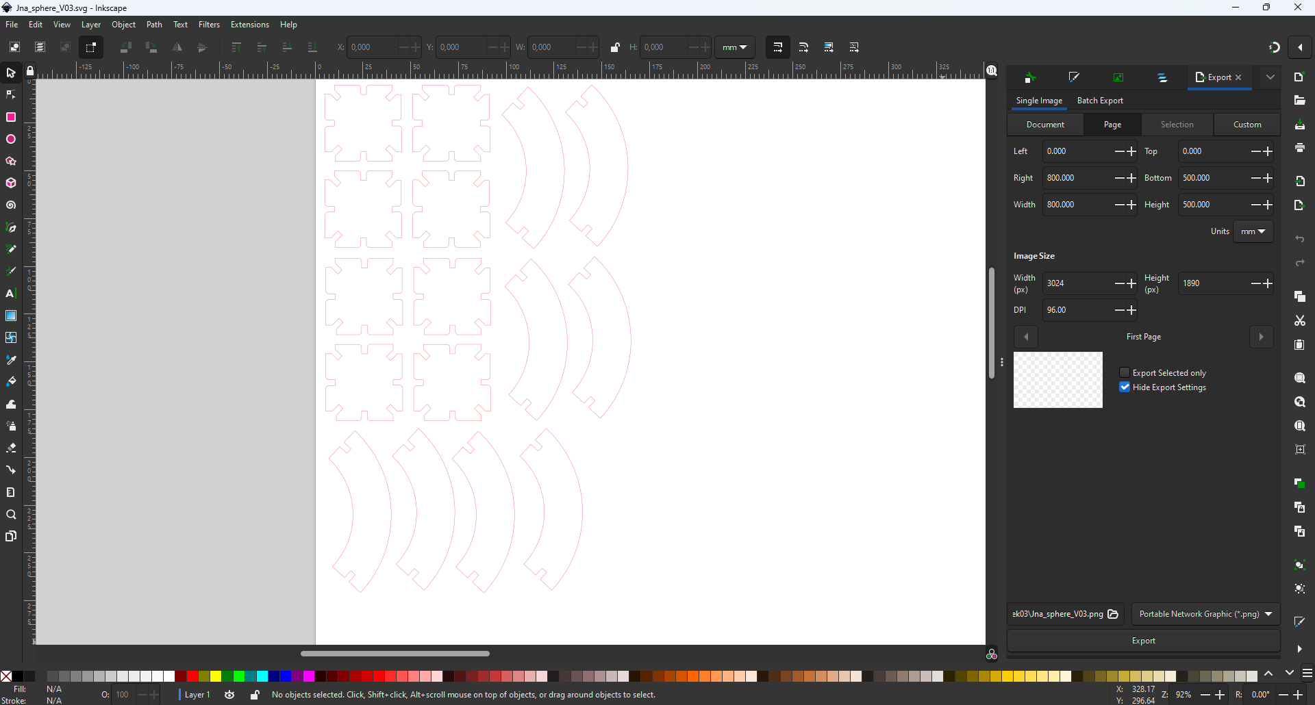
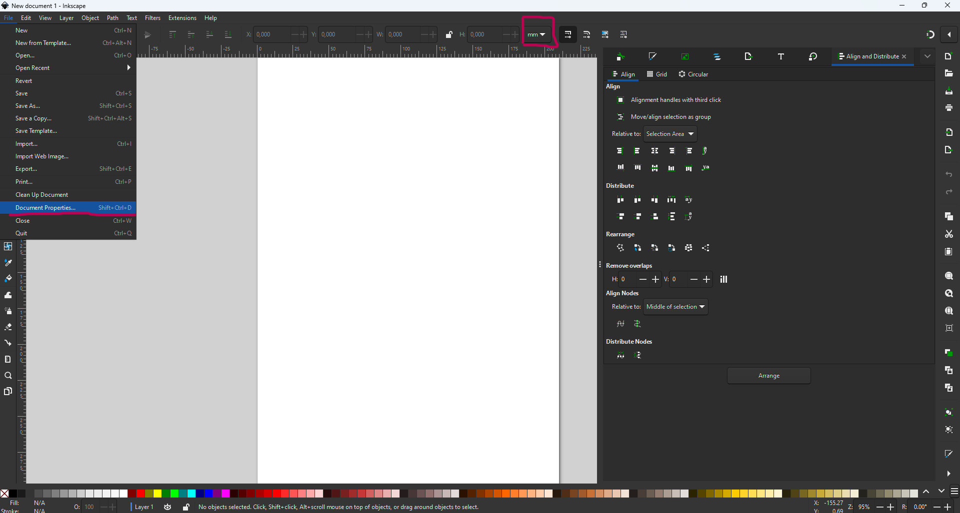
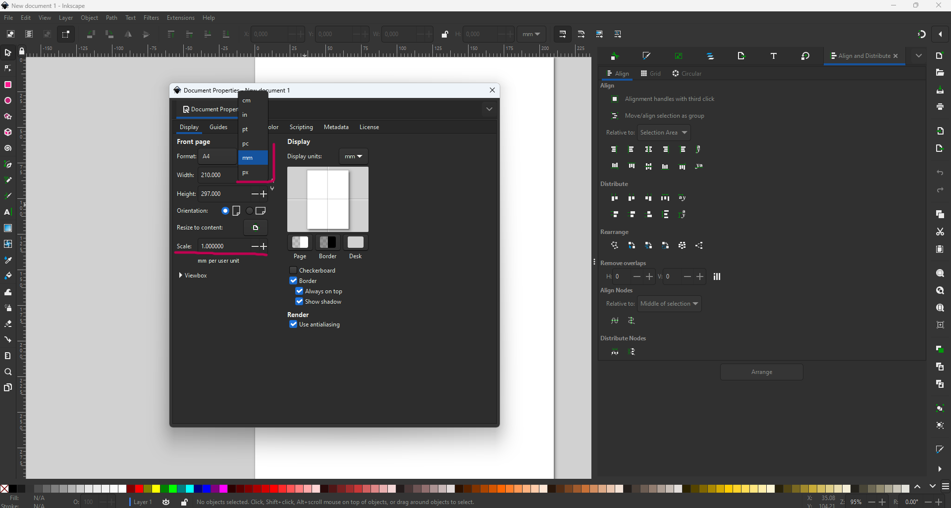
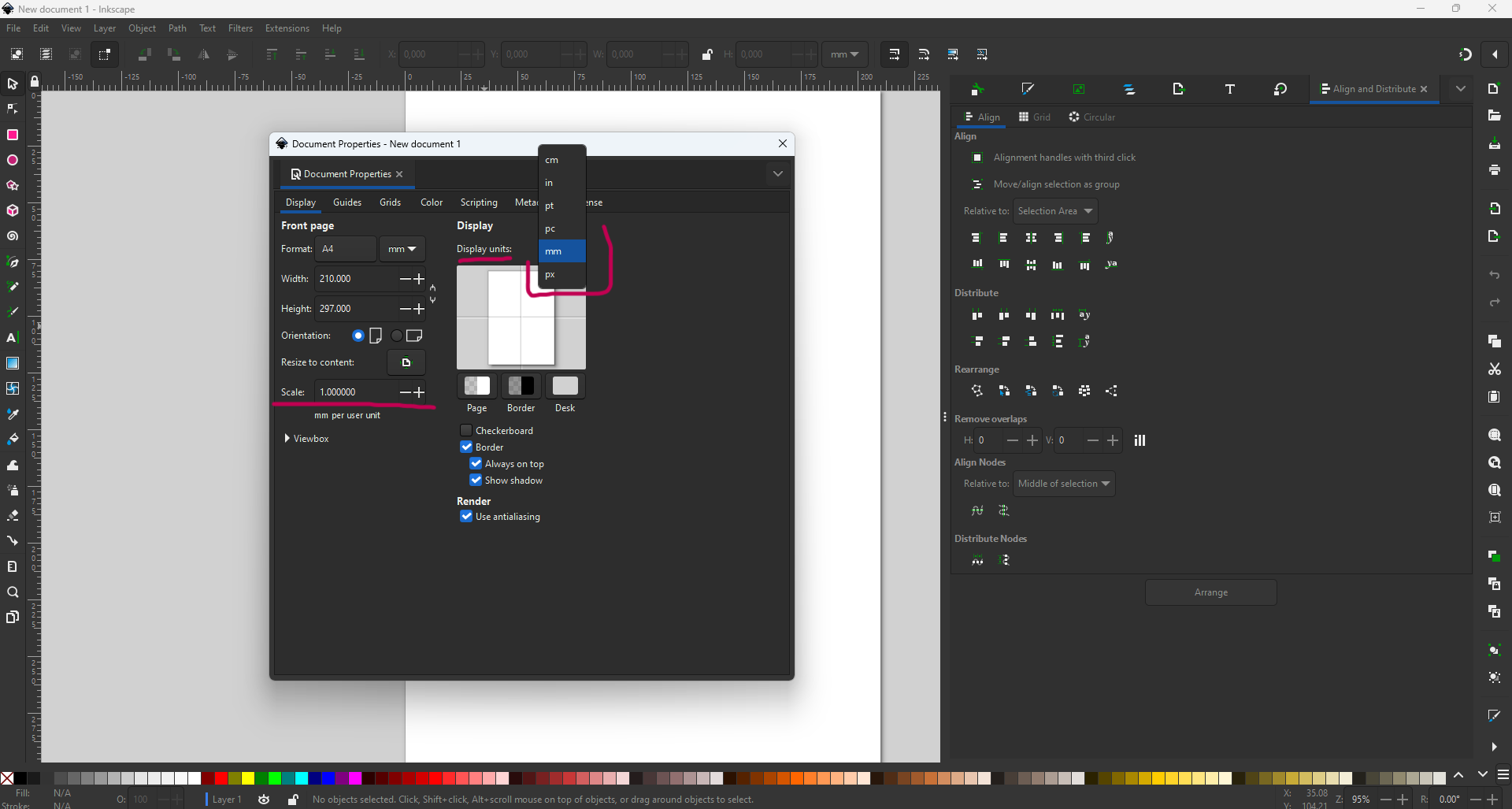
However, the first errors were in the units. We imported the DXF file in mm and the Inkscape software was in inches. This led to errors in the dimensions of the parts to be cut. With a little thought, we understood the problem and corrected it.
So always make sure you’re working in the same unit sizes, or be able to scale after a few calculations. The image below shows where to scale and where to check the units used.
3. Vynil Cutter
3.1. My vynil Cutter
3.1.1. Vinyl Cuter Roland GS-24 NEW2542
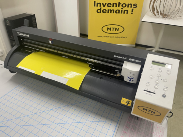
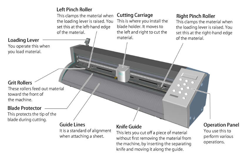
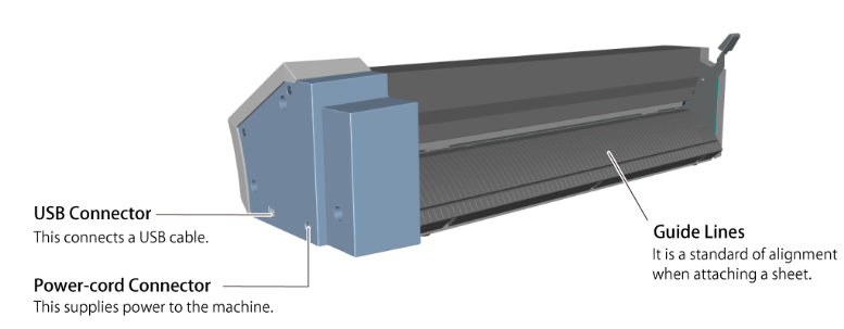
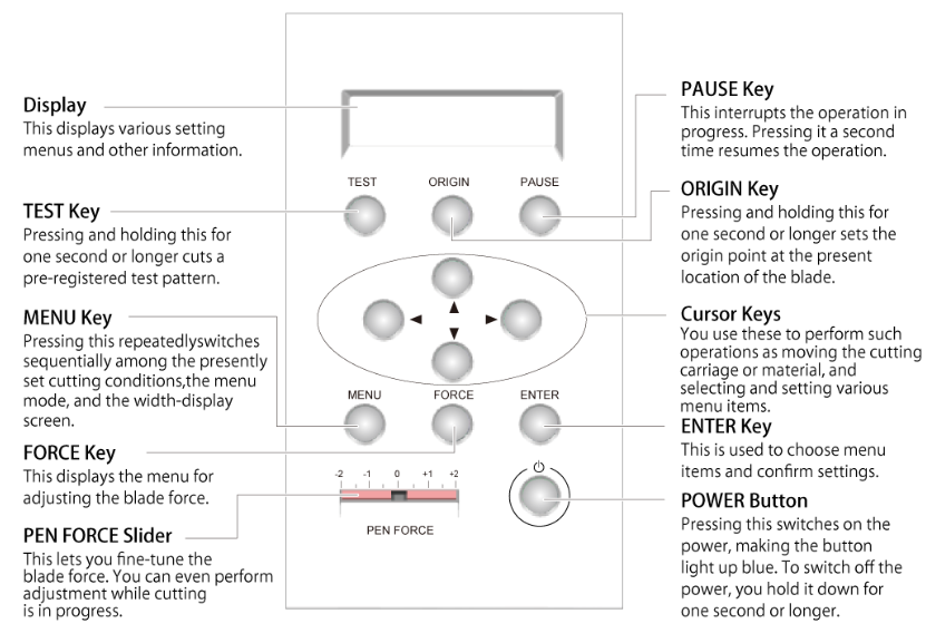
3.1.2. Part name
The part name of Roland GS-24
3.1.3. What the GS-24 can be Used For
-
Cutting Characters and Shapes Cleanly
-
Making Simple Stickers by Connecting to a Printer
-
Cutting Perforated Lines on a Variety of Materials
-
Handling Large Output Smoothly
3.1.4. Main Features
-
Dimensions of machine : 33.8”x12.5”x92.5”
-
Cutting Area : 22.9” width
-
Blade Force :30gf - 350gf
-
power Supply : Input AC 100 to 240 V
-
Software : CutStudion
-
Import file types : .bmp, .jpg, .stx, .ai, .eps
3.2. Vinyl Cutting
