02. Computer-aided Design
Part one : Assignments
-
Groupe assignment
No group assignment. -
Individual project
- Model (raster, vector, 2D, 3D, render, animate, simulate, …) a possible final project, compress your images and videos, and post it on your class page
- Modelled experimental objects/part of a possible project in 2D and 3D sofware
- Shown how you did it with words/images/screeshots
- Included your original design files.
-
Task
- Modelled experimental objects/part of a possible project in 2D and 3D software
- Shown how you did it with words/images/screenshots
- Included your original design files
Part two : What you will learn with me
We will learn how to make 2D and 3D models. For this we will use software. There are several softwares, but we will see some of them. Let’s go !
Overview
- In computer science, an image may be described to :
- A set of points called pixels, we use the term raster image.
-
A set of lines, circles, mathematical formulas, we are speaking of a vector image.
-
This representation can be in several dimensions
- when it has two dimensions, we speak of 2D image
- when it has three dimensions, it is called a 3D image
To design these images in computer, we will use software some are specialized for the images raster, vector, 2D or 3D. We will see how to use them.
For a better understanding
-
What is an image
An image is a visual representation of something.
-
How to represent an image in computer science
2.1. With a set of points defined as pixels
Pixel (or “picture elements”) are the smallest controllable unit of a digital image.
we can identify at this level two types of images: bitmap images and pixelmap images
-
Bipmap images
Bitmap images are comprised of mapped bits. This means that the image information is stored as a series of values that are either zeros or ones. This gives a computer a way to store a binary image made up of black and white pixels.
-
pixelmap images
Pixel maps can store more than one bit (color) per pixel. In computer graphics the two terms are often used interchangeably.
Raster
The term “raster” is used to describe both bitmaps and pixelmaps and indicates that these graphics are resoultion dependent. If you resize a raster graphic to a larger size, the square pixels will become apparent.
2.2. With a set of lines, curves, and mathematical expressions
Vector graphics are resolution independent. They are based on mathematical expressions and use points, lines, curves and polygons to represent images. Because they use mathmatical formulas, they can be resized, bent and stretched without losing resolution. Lines remain crisp and sharp when the size of the drawing is increased.
2.3. Links
- Fab Academy Tutorial : 2D Design Tools and Tutorials
-
How to use software
-
2D Design Tools for Raster
1.1. GIMP
1.1.1. What is GIMP
GIMP is an acronym for GNU Image Manipulation Program available for GNU/Linux, macOS, Windows and more operating systems. It is a freely distributed program for such raster graphics tasks as photo retouching, image composition and image authoring.
1.1.2. How to use GIMP during Fab Academy
GIM may be used during the fab academy to
- resize photos
- design a logo
1.1.3. Install GIMP
- Download GIMP here
- Install GIMP
1.1.4. GIMP Quickies
-
Changing the Size (Dimensions) of an Image (Scale)
step_01 : Open GIMP and find your image ( file → Open)
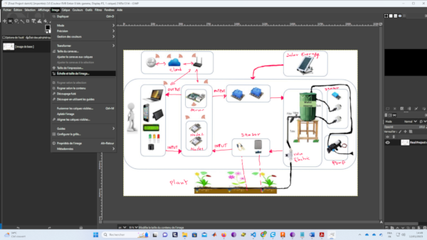
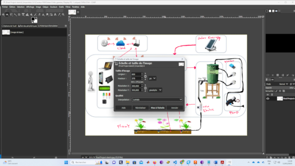
step_02 : Scale Image dialog (Image → Scale Image…)
step_03 : change the size
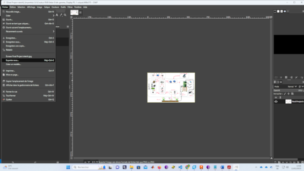
step_04 : export the changes (File → Export…)
-
Crop an Image
step_01 : Open GIMP
step_02 : find your image and you can access the crop tool through the menus ( Tools → Transform Tools → Crop)
step_03 : press the “Enter” key on your keyboard to commit the crop
-
2D Design Tools for vector
2.1. Inkscape
2.1.1. What is Inkscape
Inkscape is a Free and open source vector graphics editor for GNU/Linux, Windows and macOS. It offers a rich set of features and is widely used for both artistic and technical illustrations such as cartoons, clip art, logos, typography, diagramming and flowcharting. It uses vector graphics to allow for sharp printouts and renderings at unlimited resolution and is not bound to a fixed number of pixels like raster graphics. Inkscape uses the standardized SVG file format as its main format, which is supported by many other applications including web browsers.
2.1.2. How to use Inkscape during Fab Academy
- to presente your final project
- to make a logo
- to design your website
2.1.3. Install Inkscape
Step_01: Dowload Inkscape
 Step_02: Install Inkscape
2.1.4. Inkscape Quickies
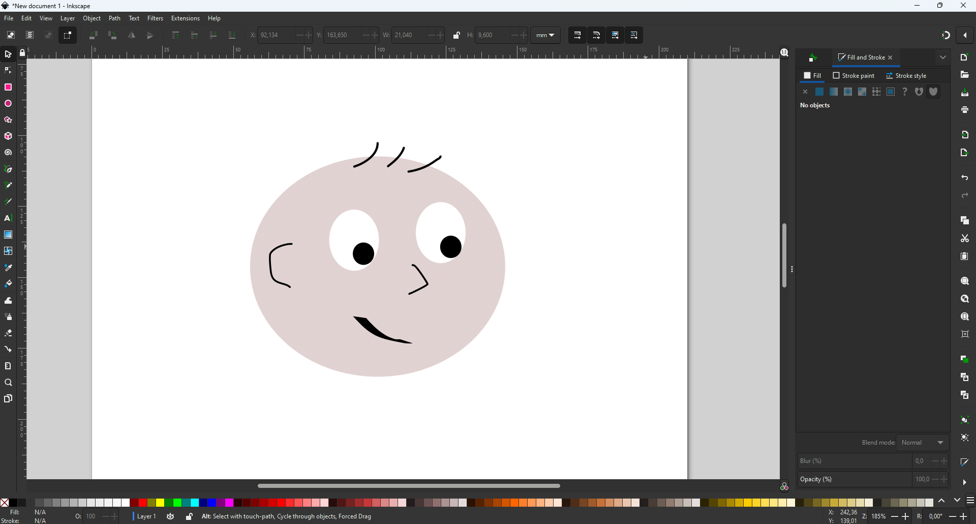
Step_01: When first run, Inkscape starts by showing a helpful welcome dialog * Its first tab, Quick Setup, lets you tweak the program’s appearance and behavior * On the Time to Draw tab of this dialog, you can select one of the recently edited documents or one of the new document templates. Also on this tab, you can uncheck Show this every time to avoid seeing the dialog in the future
Step_02:Chose a document or pressing Esc, Inkscape opens its main editing window
Step_03: draw
2.1.5. Vectoring a raster image
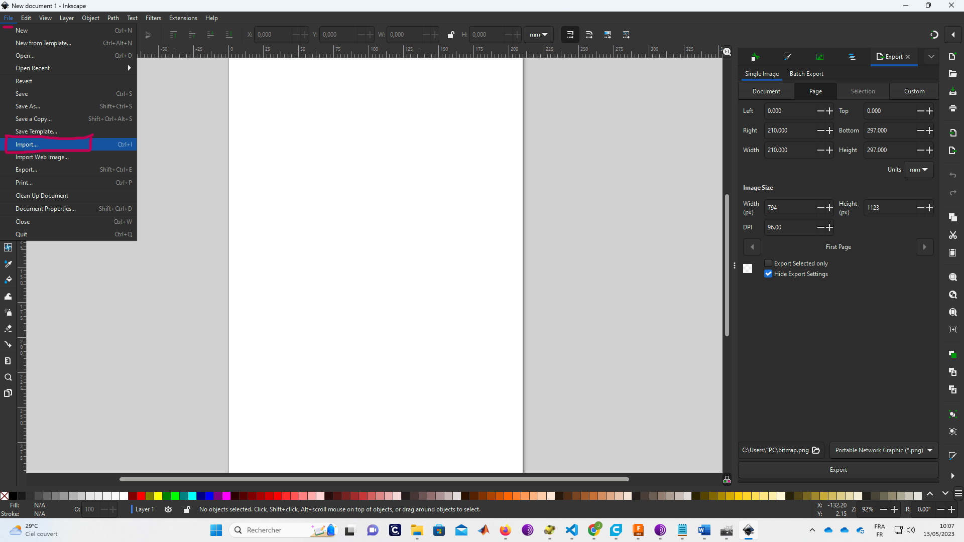
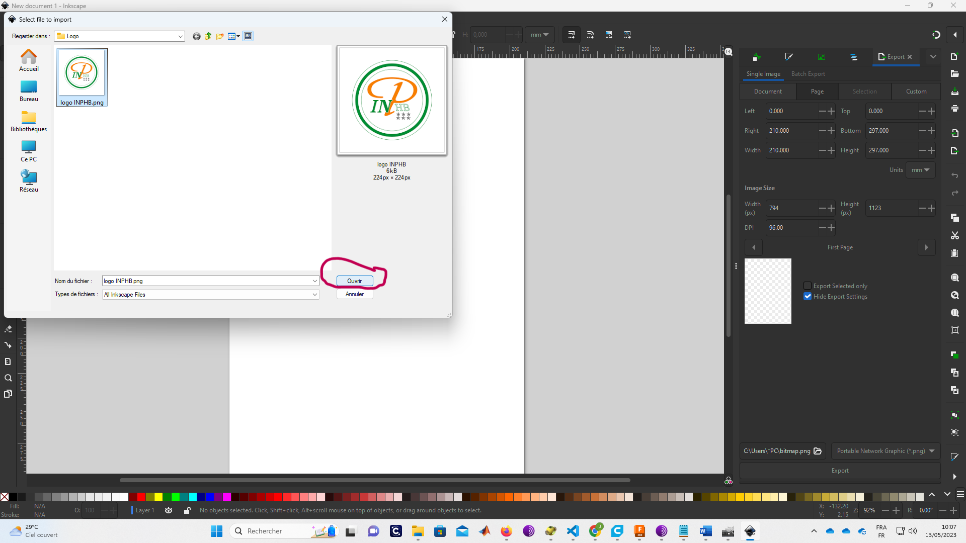
Step_01: Open Inkscape and Import an Image
 Step_02: Go to “Path” and clic on ” Trace Bipmap…”
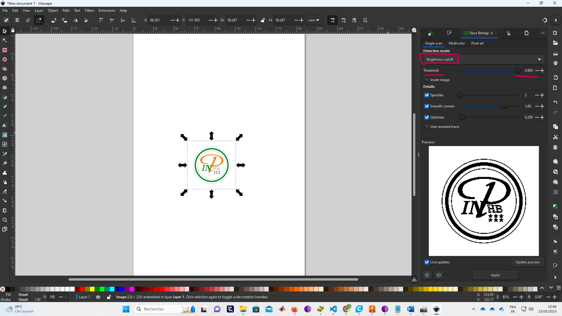
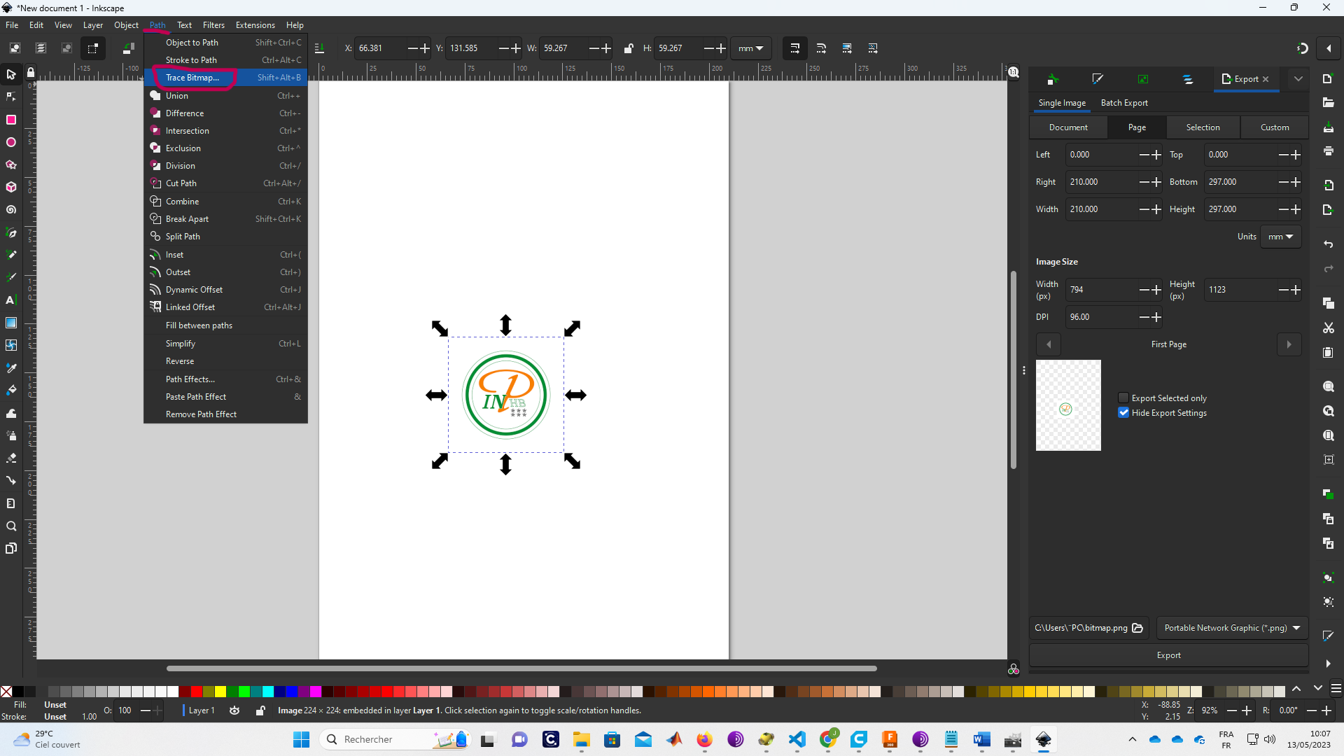 Step_03: Chose “Brightness cutoff” and modifie the Threshold
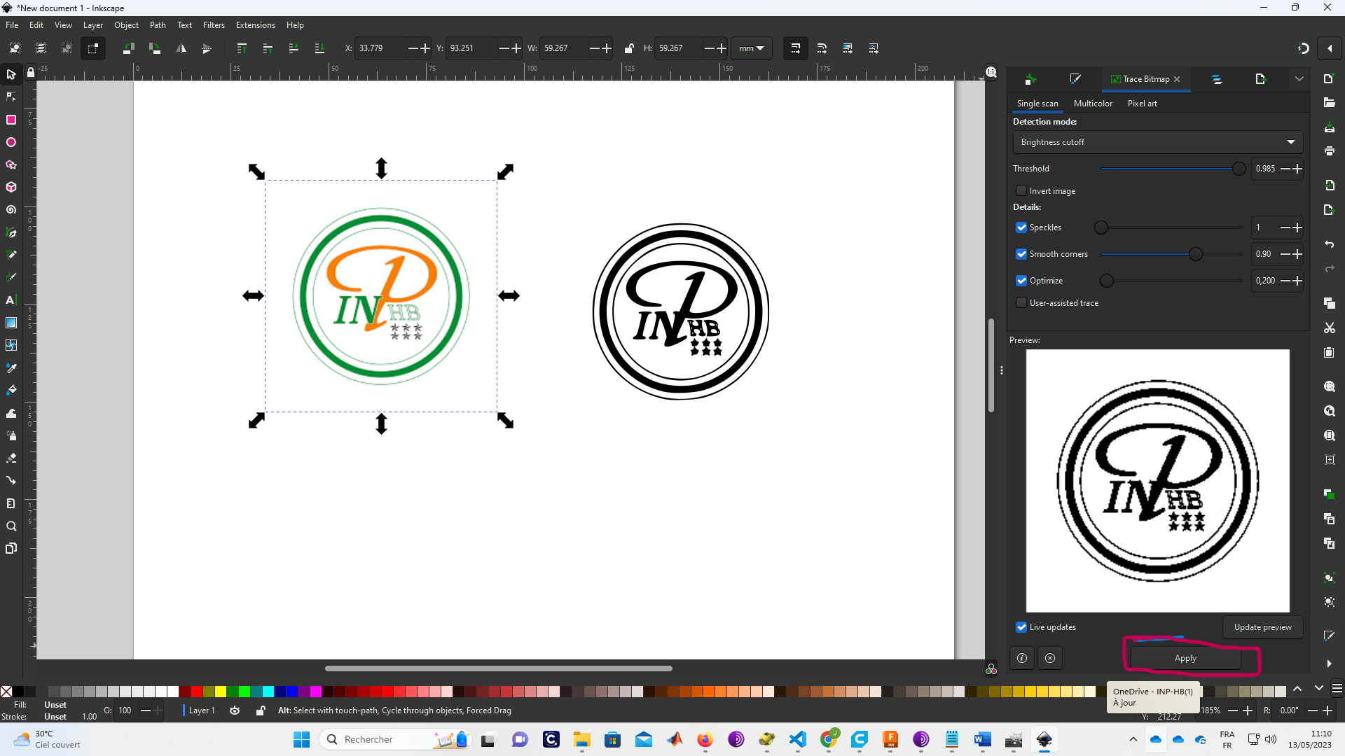
 Step_04: Clic on “apply” ang save your work
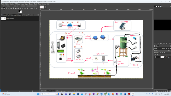
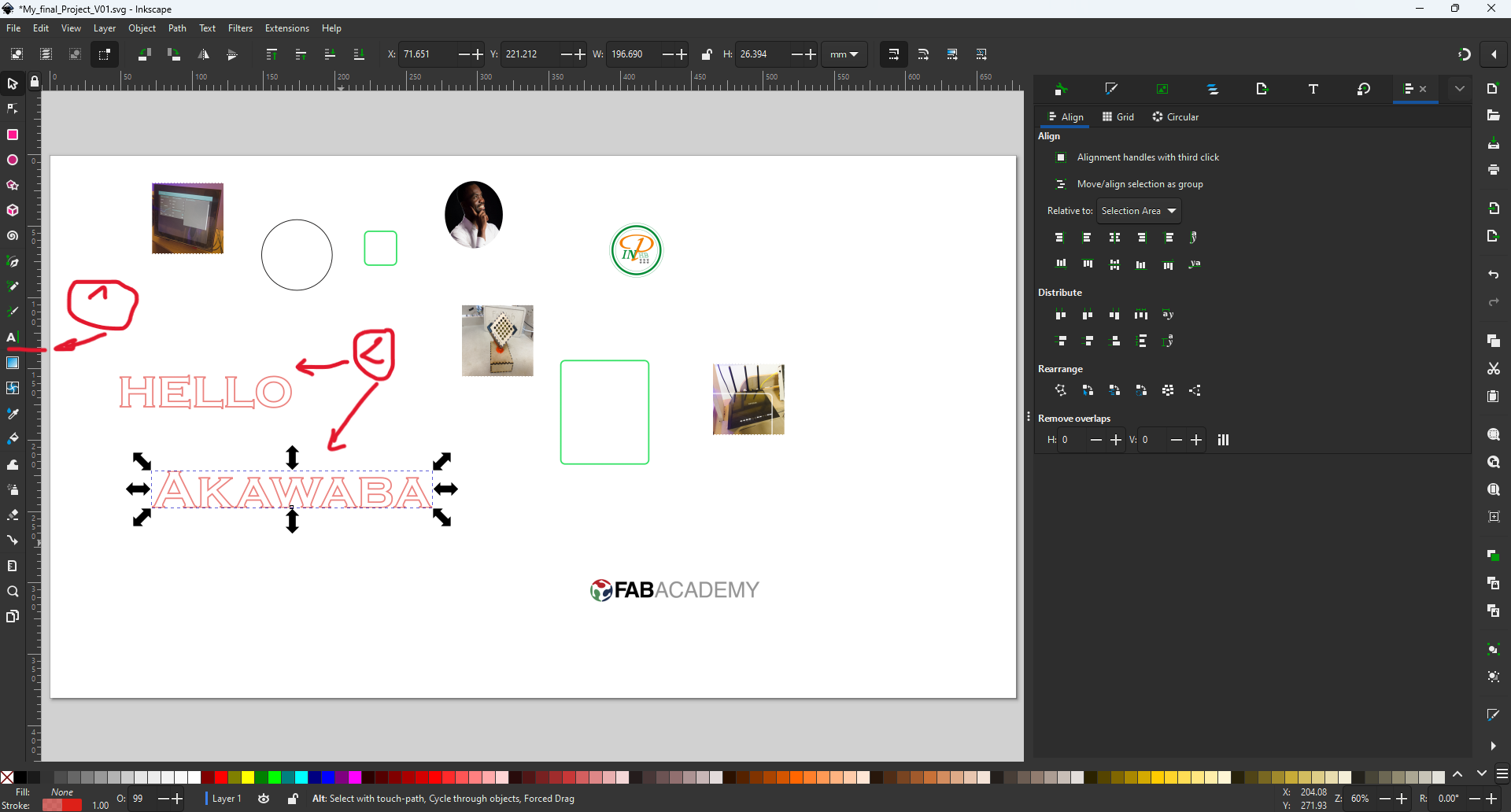
2.2. Use Inkscape to make slide for my Final Project
My slide made with Inkscape.
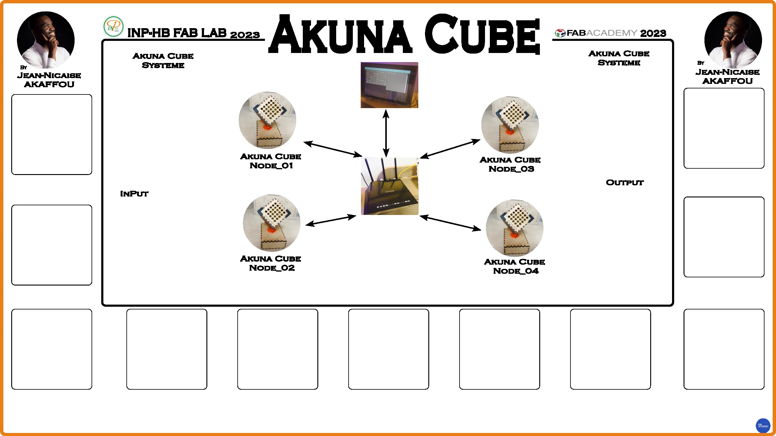
To achieve this, I used the functions described in each step.
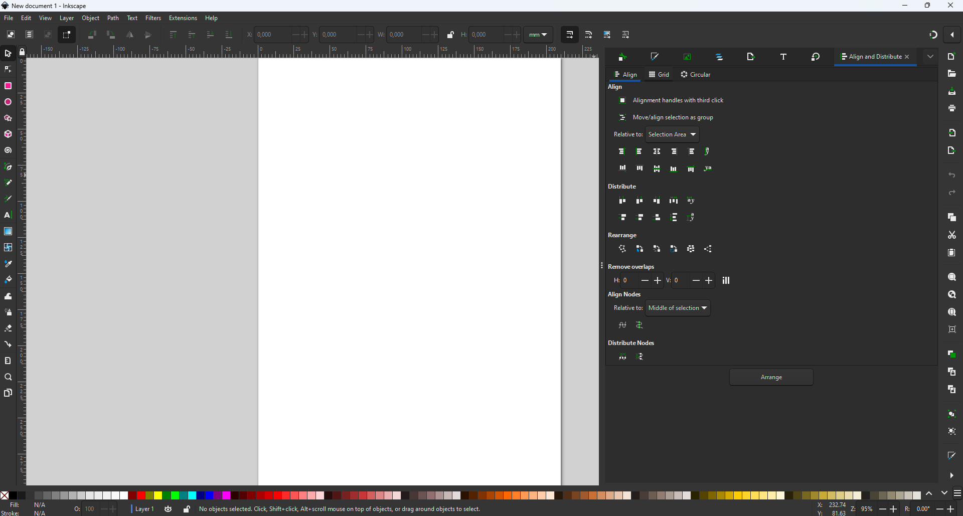
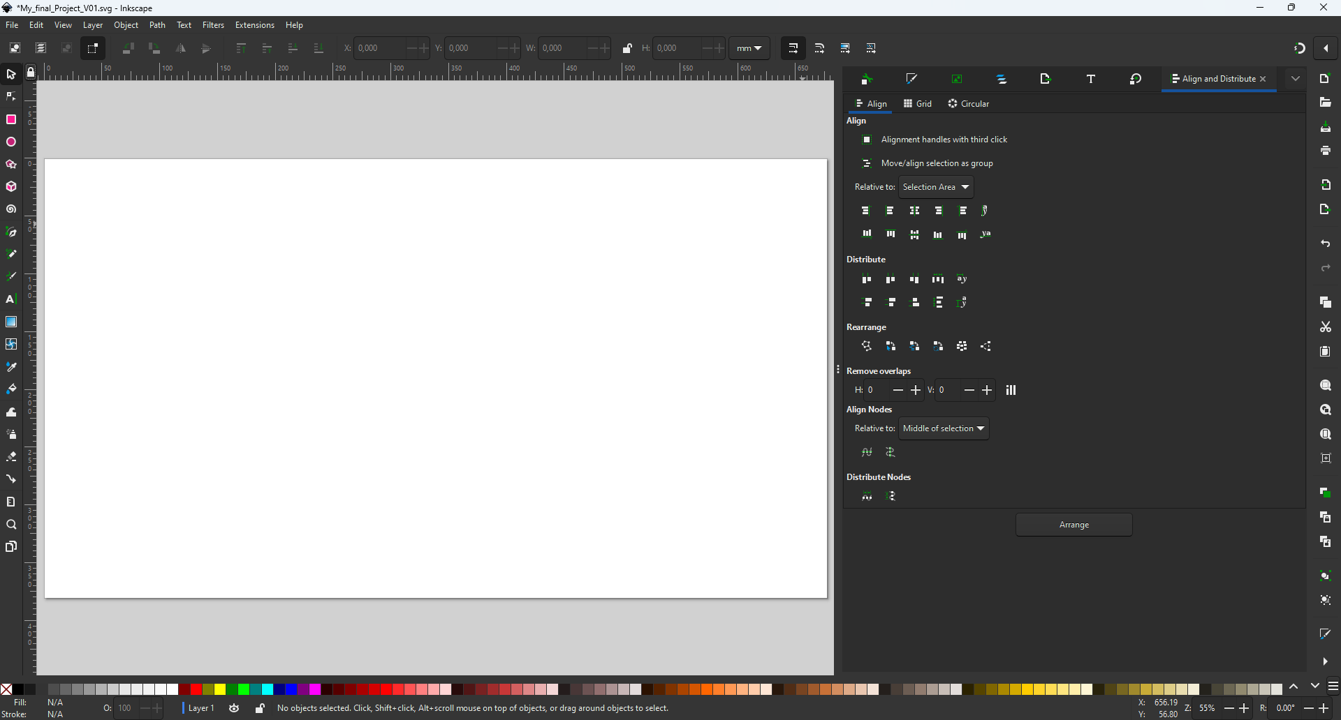
Step_01: Open Inkscape
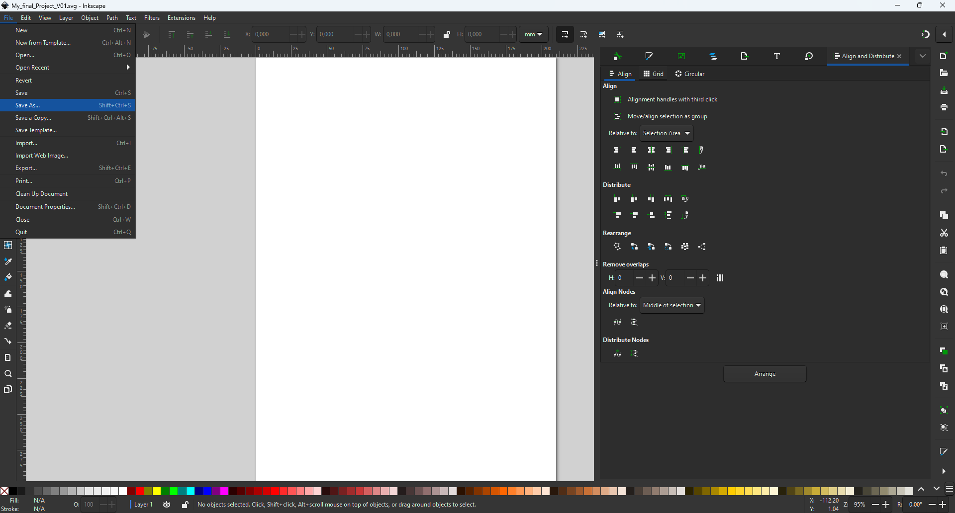
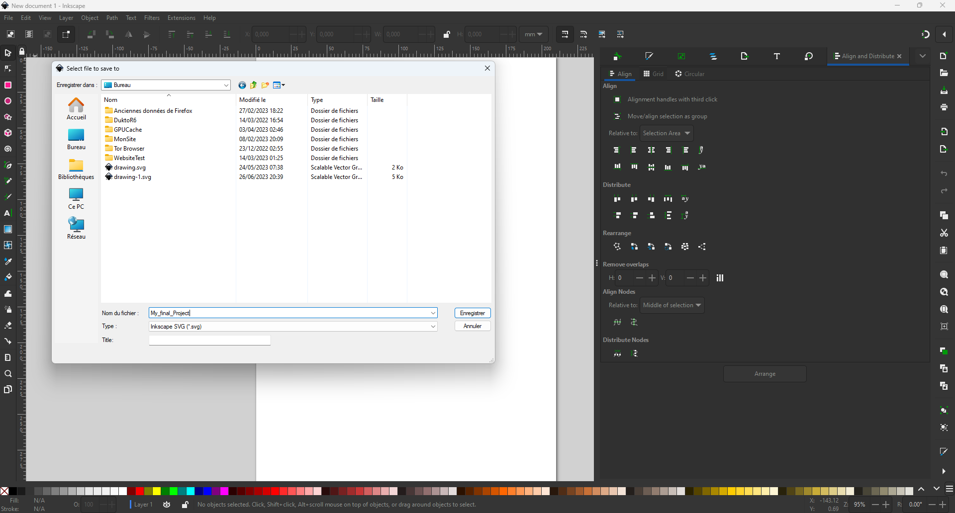
Step_02: Save your document
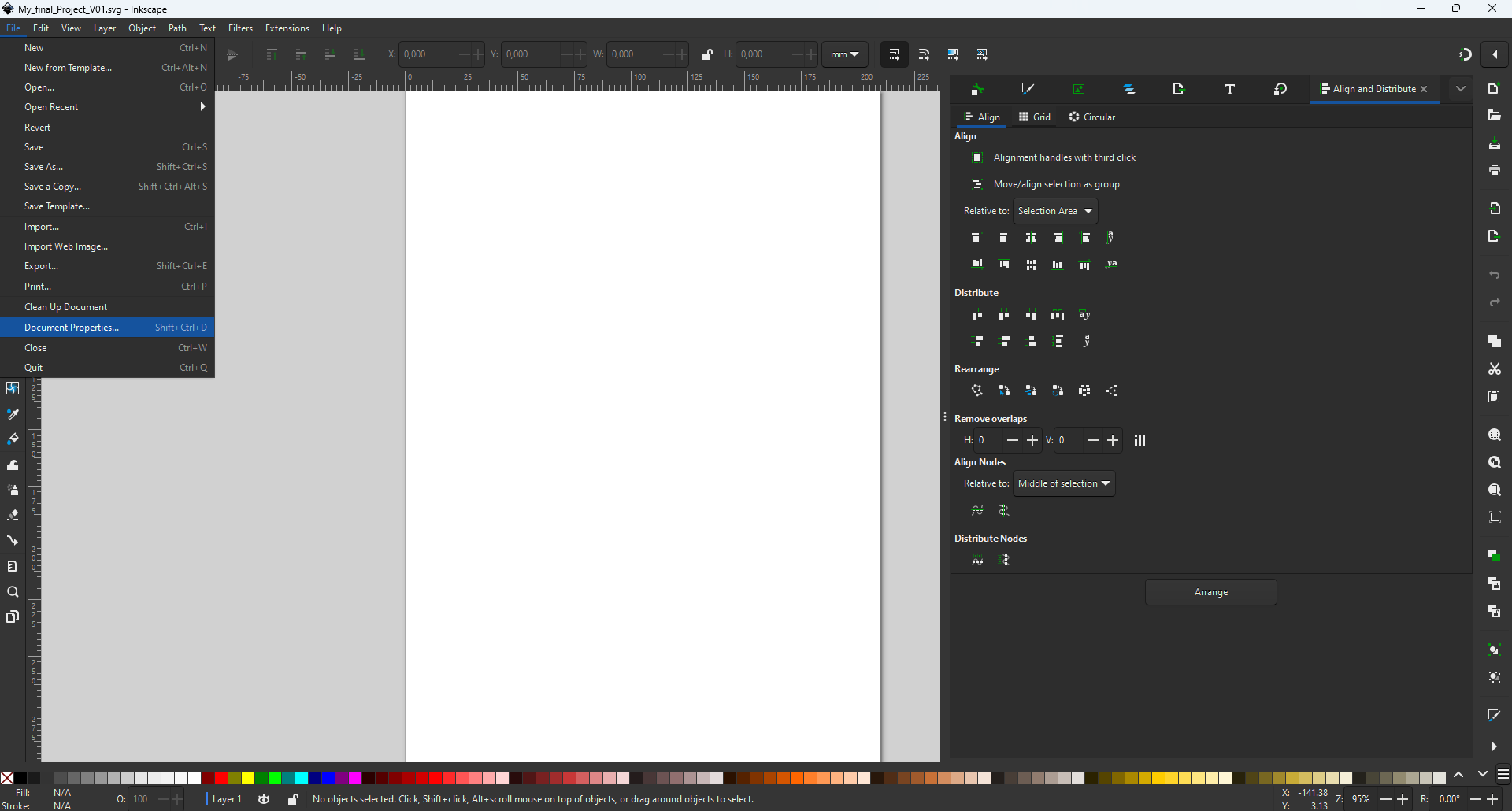
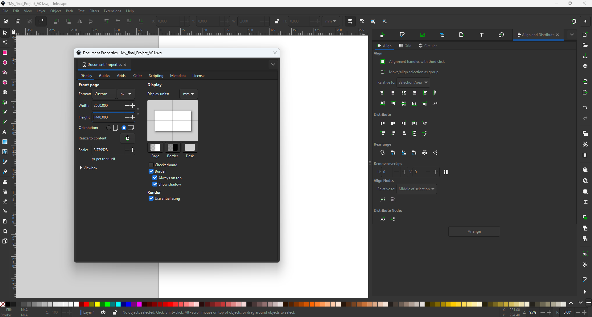
Step_03: Define work space dimensions
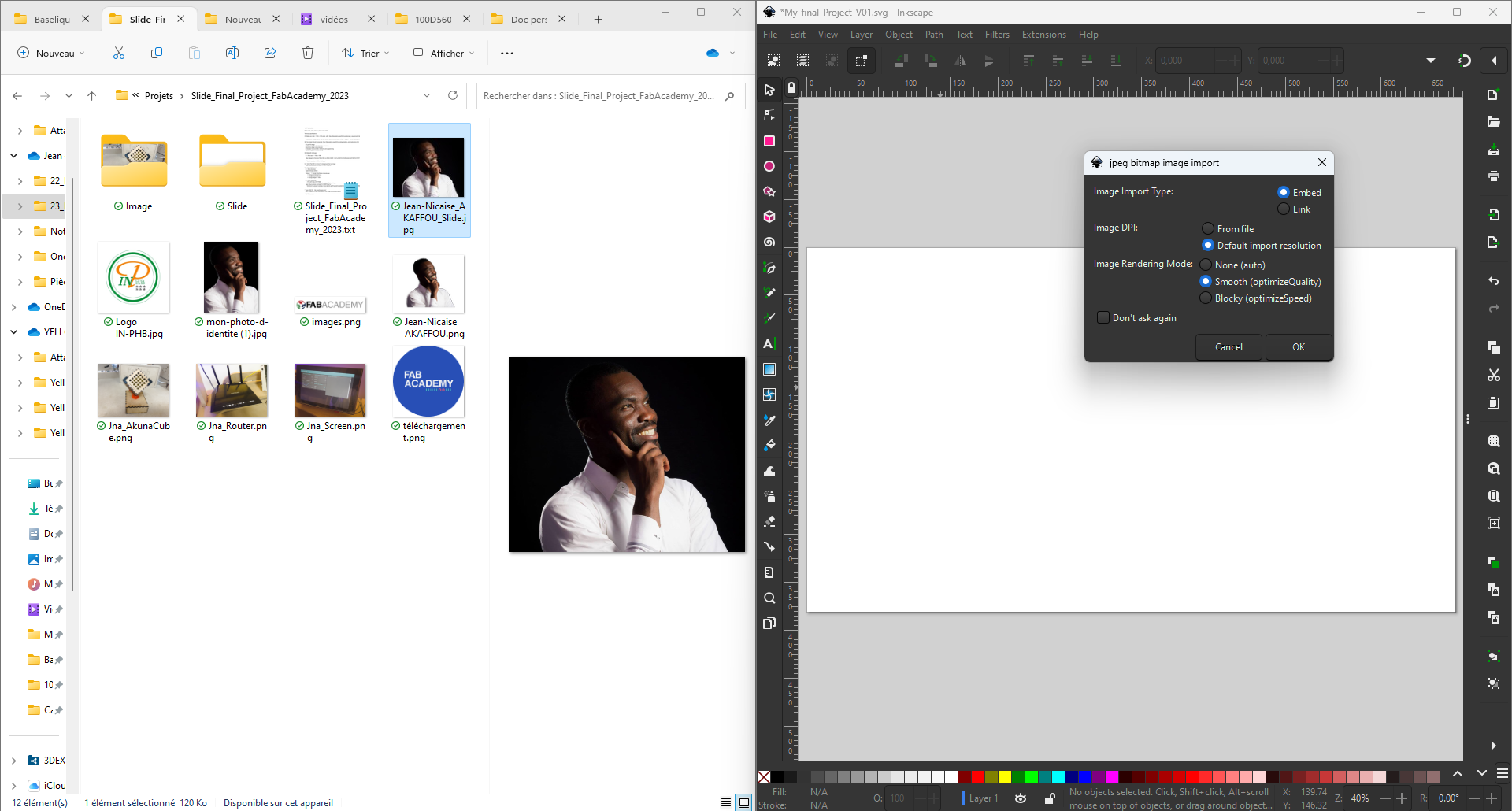
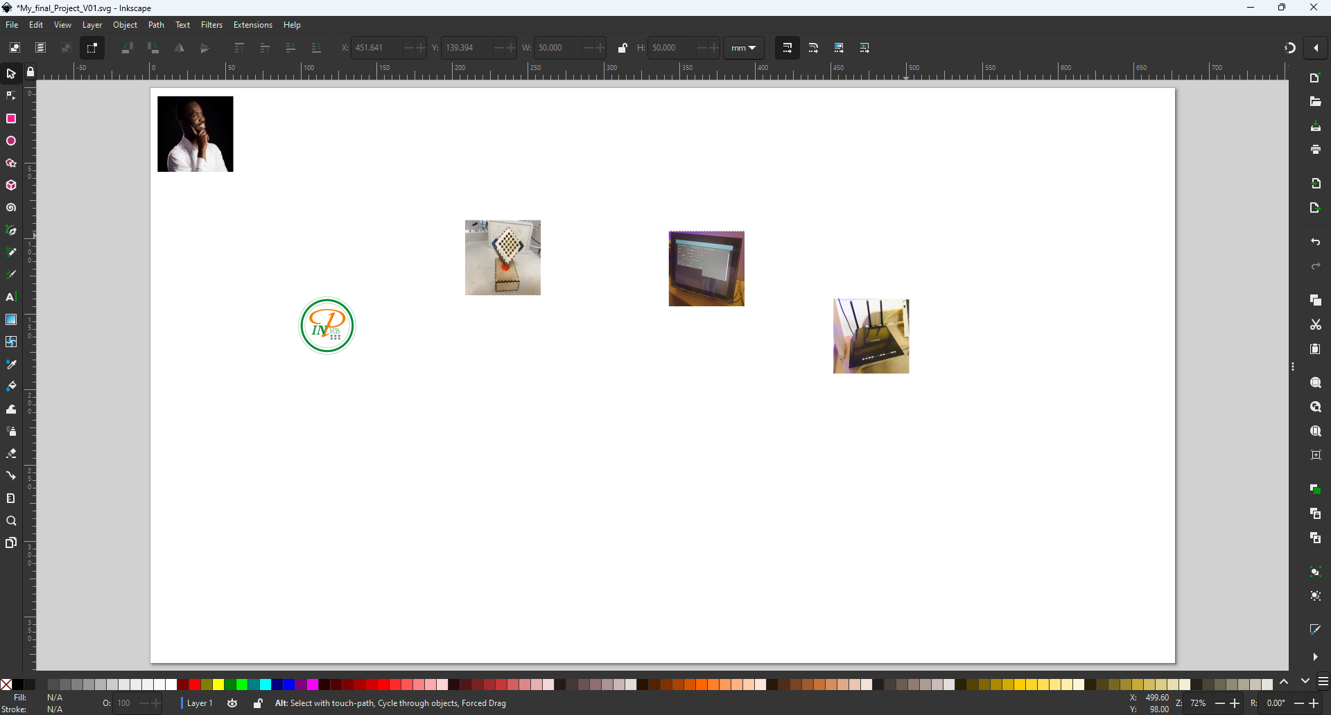
Step_04: Place images in workspace
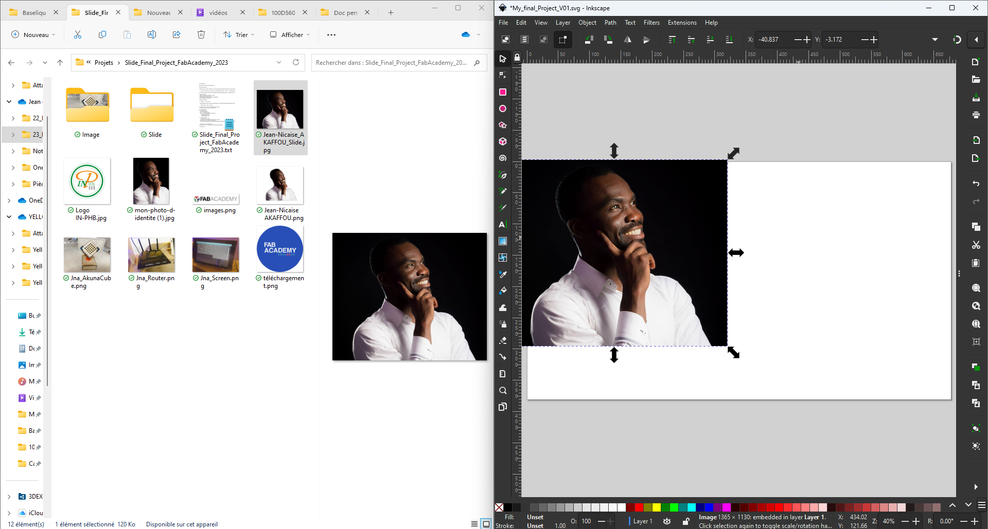
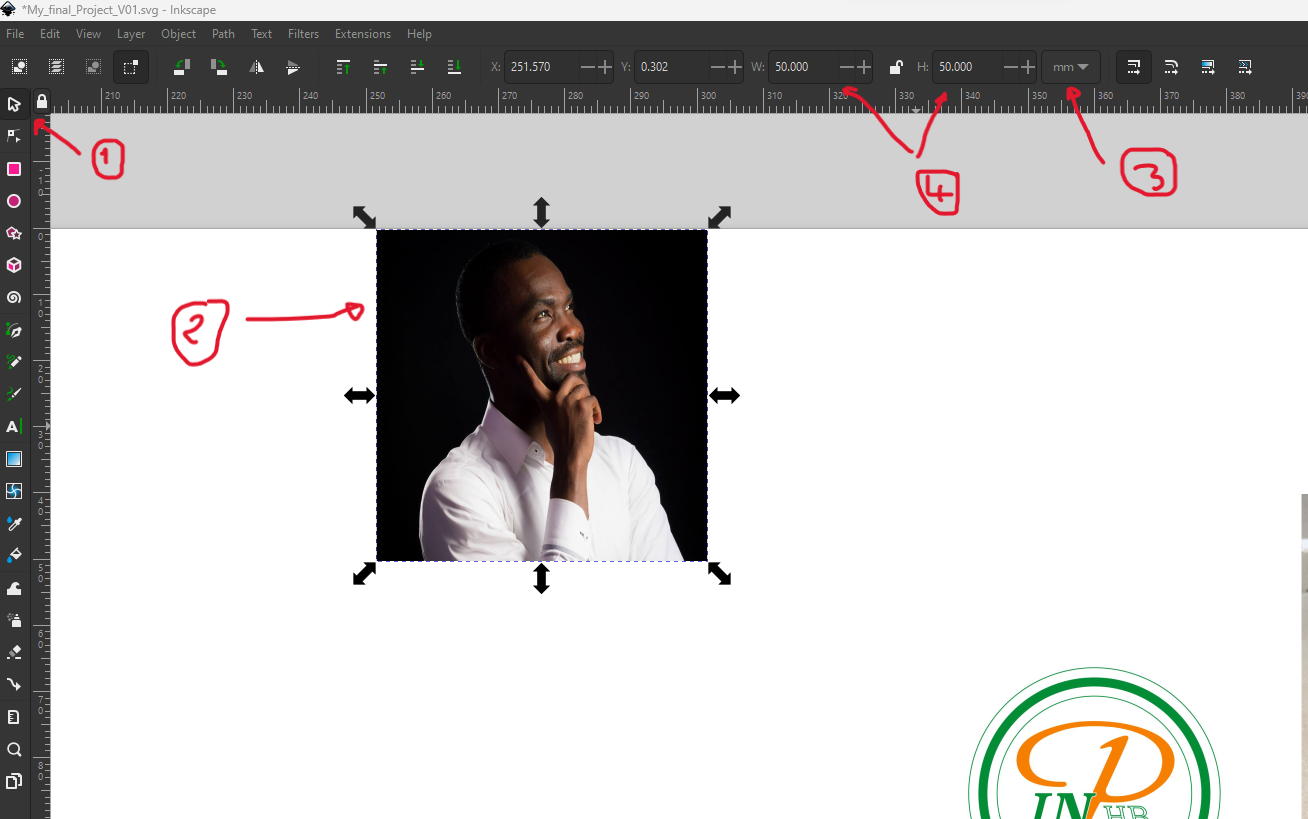
Step_05: Resize images
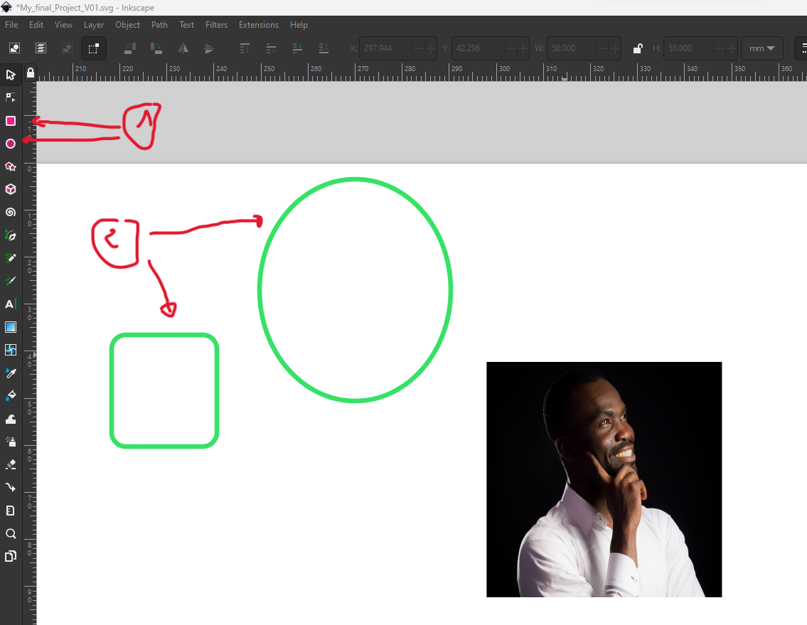
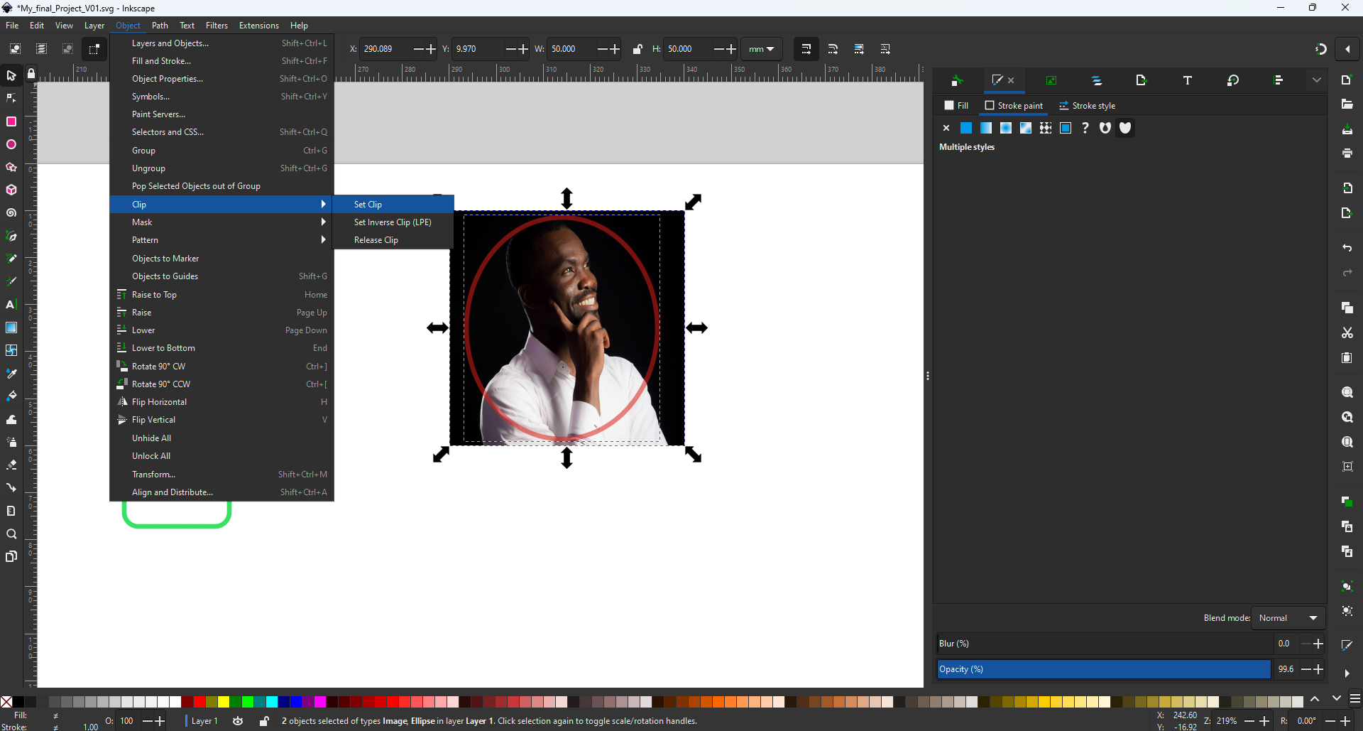
Step_06: Draw a circle and rectangle
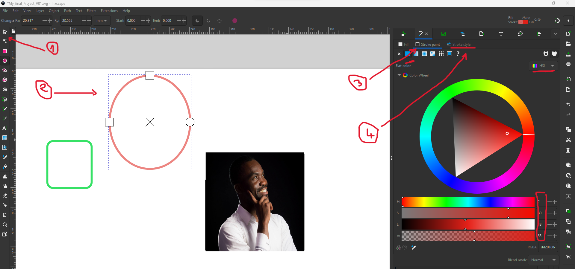
Step_07: change color and type of shape
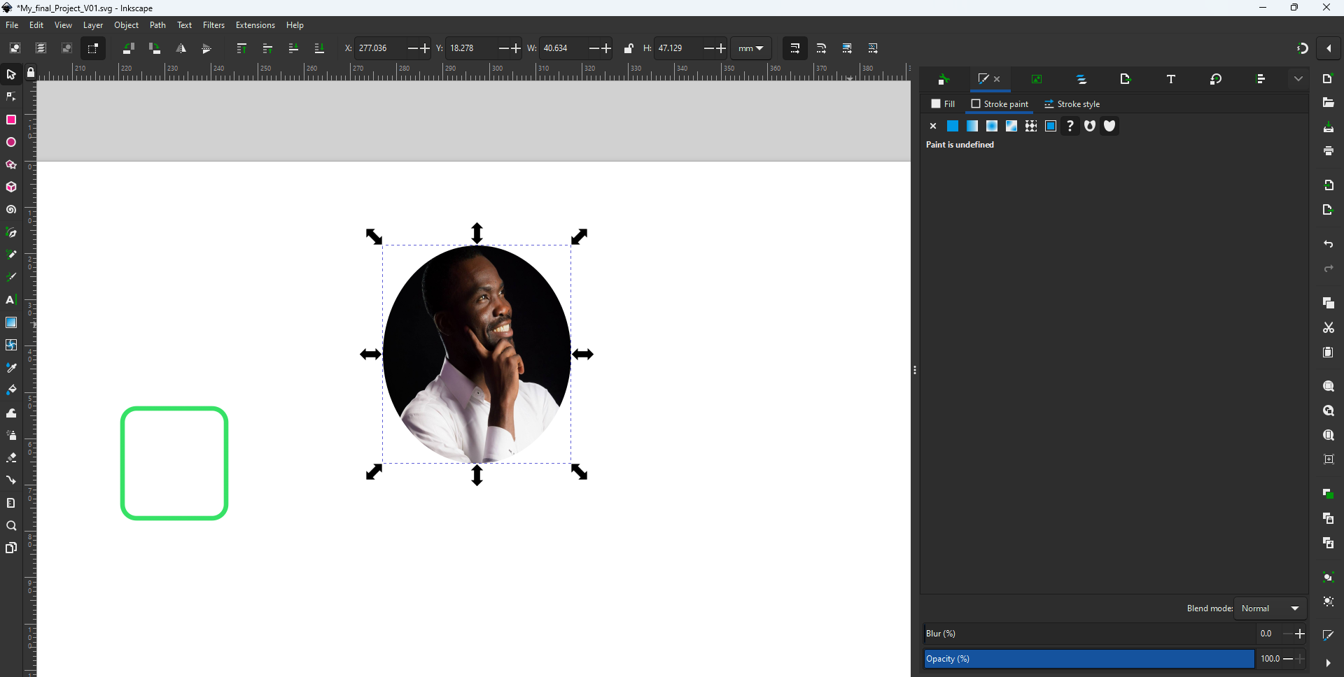
Step_08: give images a circular shape
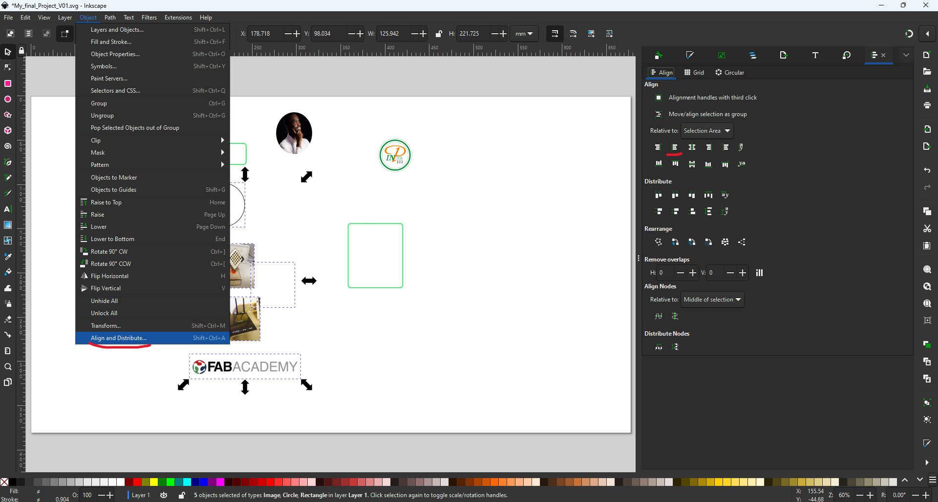
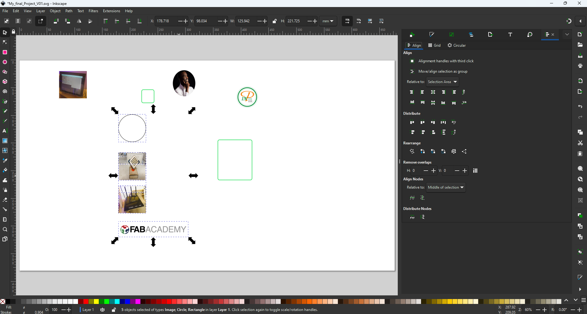
Step_09: Align a picture
Step_10: Add text to the image
-
3D Design Tools
3.1. OpenSCAD
3.1.1. What is OpenSCAD
OpenSCAD is software for creating solid 3D CAD models. It is free software and available for Linux/UNIX, Windows and Mac OS X. Unlike most free software for creating 3D models (such as Blender) it does not focus on the artistic aspects of 3D modelling but instead on the CAD aspects. Thus it might be the application you are looking for when you are planning to create 3D models of machine parts but pretty sure is not what you are looking for when you are more interested in creating computer-animated movies.3.1.2. How to use OpenSCAD during Fab Academy
OpenSCAD is a solid 3D modeler that enables the creation of parametric models using its scripting language. Models are created by utilizing a technique called constructive solid geometry. According to this technique, simple objects can be transformed and combined in order to create almost any complex model.
3.1.3. Install OpenSCAD
Step_01:Dowload OpenSCAD
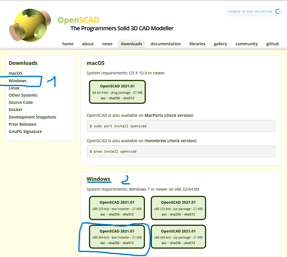
Step_02: Install
3.1.4. OpenSCAD Quickies
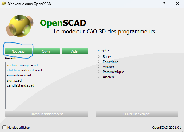
Step_01: Run OpenSCAD
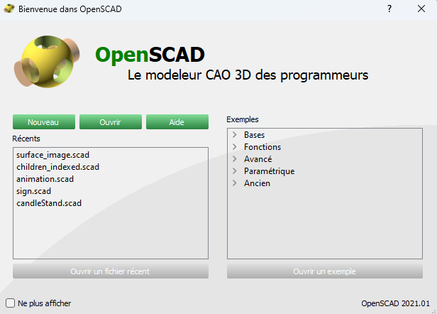
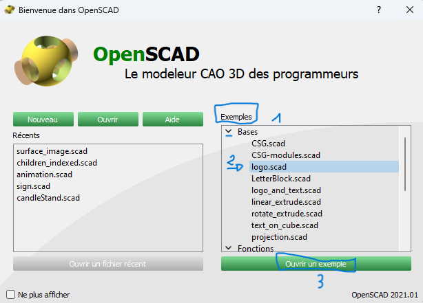
Step_02: Open existing file
Step_03: Open new file
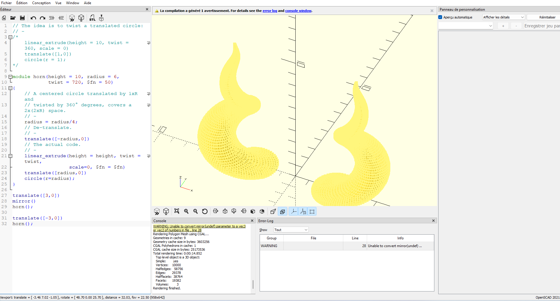
Step_04: Create a cube
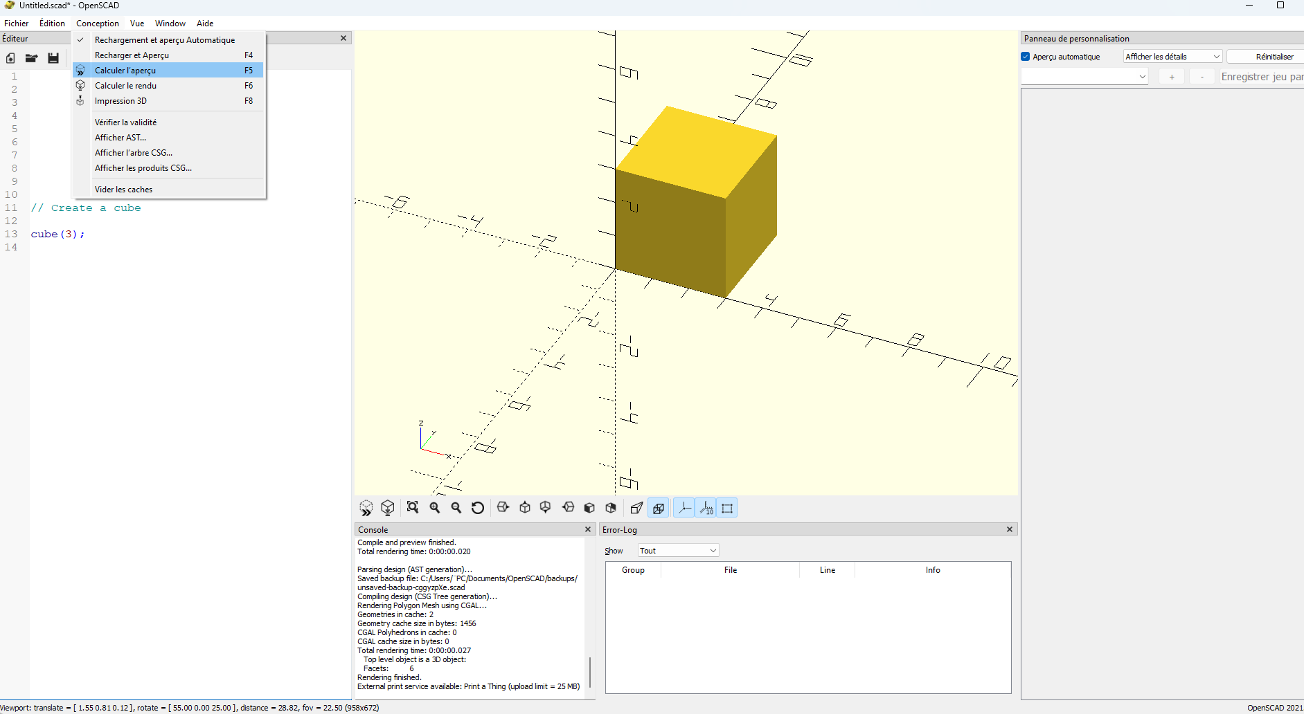
Step_04: Horns
```c++ title=”Horns programm for OpenSCAD” linenums=”1”
 // The idea is to twist a translated circle:
 // -
 /*
  linear_extrude(height = 10, twist = 360, scale = 0)
 translate([1,0])
 circle(r = 1);
 */

 module horn(height = 10, radius = 6,
 twist = 720, $fn = 50)
 {
 // A centered circle translated by 1xR and
 // twisted by 360° degrees, covers a 2x(2xR) space.
 // -
 radius = radius/4;
 // De-translate.
 // -
 translate([-radius,0])
 // The actual code.
 // -
 linear_extrude(height = height, twist = twist,
 scale=0, $fn = $fn)
 translate([radius,0])
 circle(r=radius);
 }

 translate([3,0])
 mirror()
 horn();

 translate([-3,0])
 horn();
3.2. SolidWorks
I’m going to use this software to model a key part 0f my final project. for me, it’s a cube equipped with sensors and an electronic relay capable of interacting with the home and its environment.
SOLIDWORKS is a 3D modeler using parametric design. It generates 3 types of files relating to three basic concepts: part, assembly and drawing. These files are interrelated. Any modification at any level is reflected in all the files concerned.
How to use solidworks
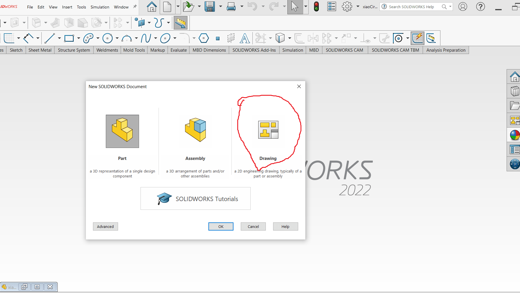
Step_1: open Solidworks
Step_2: select the mode of your activity
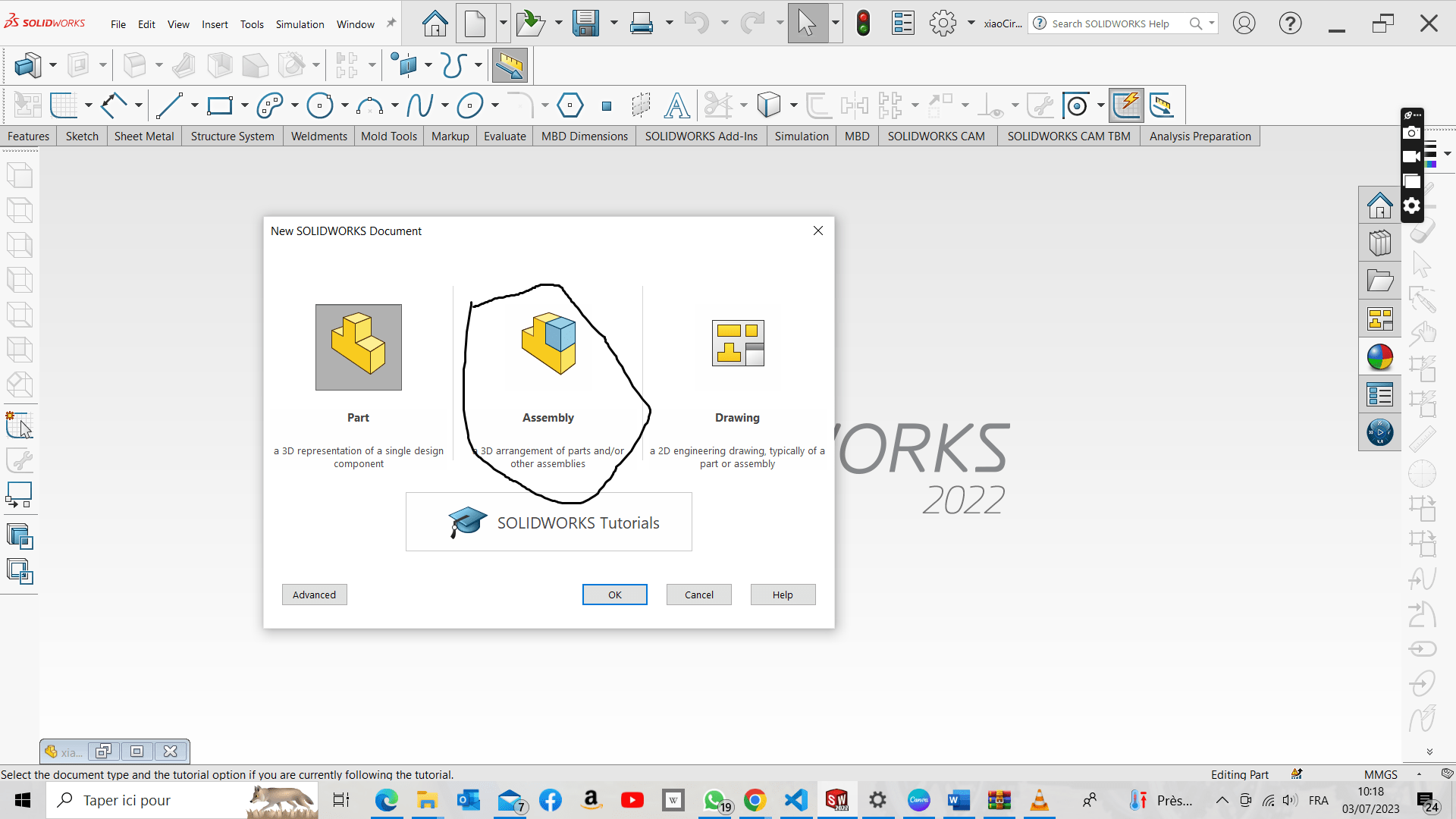 .
.- **Part** this mode allows you to draw your projet - **Assemebly** this mode allows you to make the assemebly of your projet - **Drawing** this mode allows you to it allows you to put dimensions on your drawing and turn it into a usable document.Create a Part
to start drawing, select a plane, then click on the desired plane
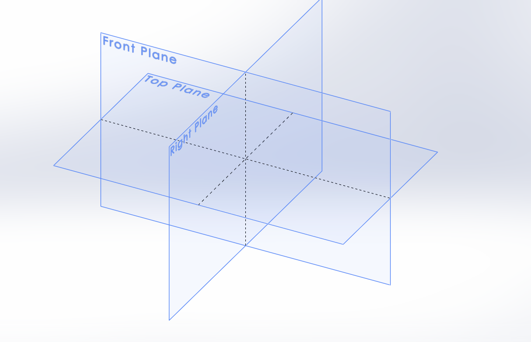 .
.you have to choose the figure you want in my case, I start with a square.
 .
.you have to make the drawing and give it a dimension. 2D drawing
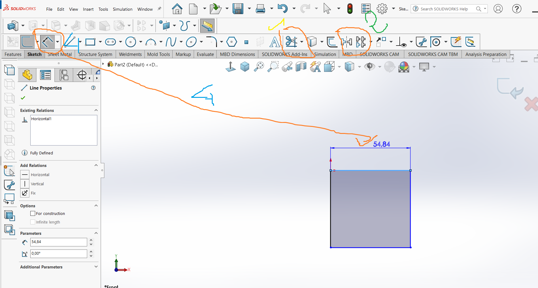 .
.1 : for delete something.
2 and 3 : for mirror sommething and partern.
4 : put a dimension.
3D drawing
 .
. .
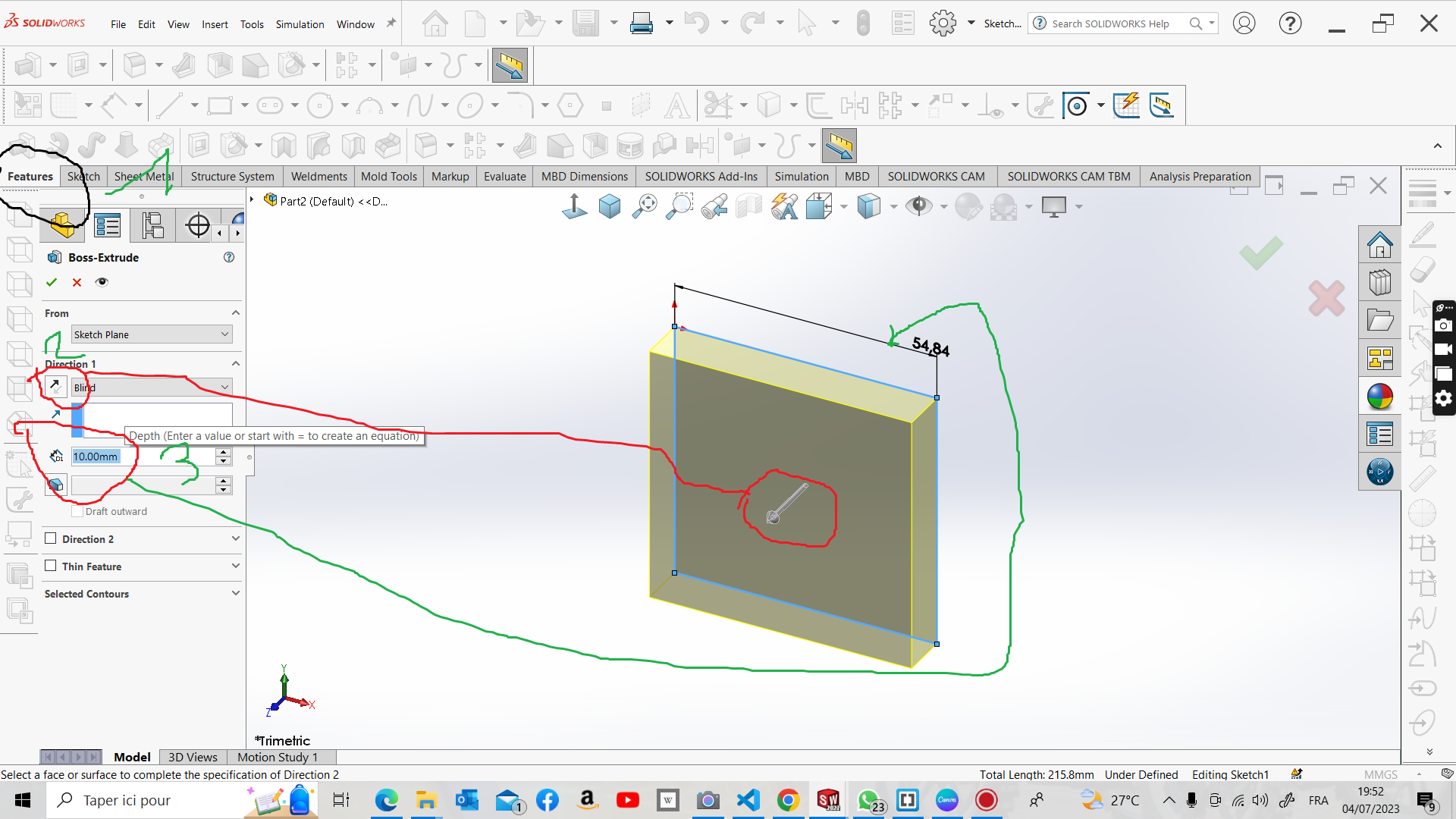
.clic on the number one icon it for extrusion
1: select Feature to create a 3D model 2: select the direction 3: put your dimension you want
.
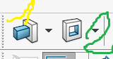
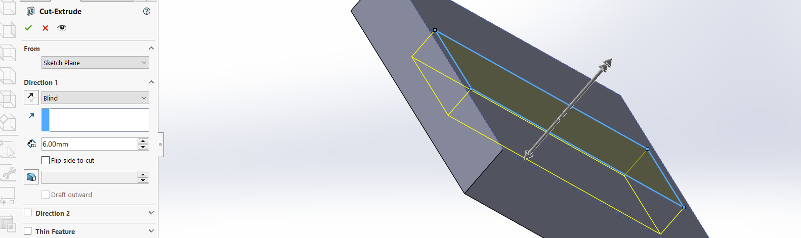
it the same thing for all cutting optionclic on the number two icon it for cutting
may be your have to do the same thing on thesolidworks bord
 .
.assembly part
you have to open new file and first of all choose assembly mode
. .
.1: for bring part from your folder 2: tool get marte fonction
all tool you have to use here
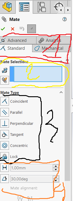 .
.1: all diferent mechanism
2: the face selection wil be here
3: mate type you have
4: dimension for face after you mate them
Explaination Video
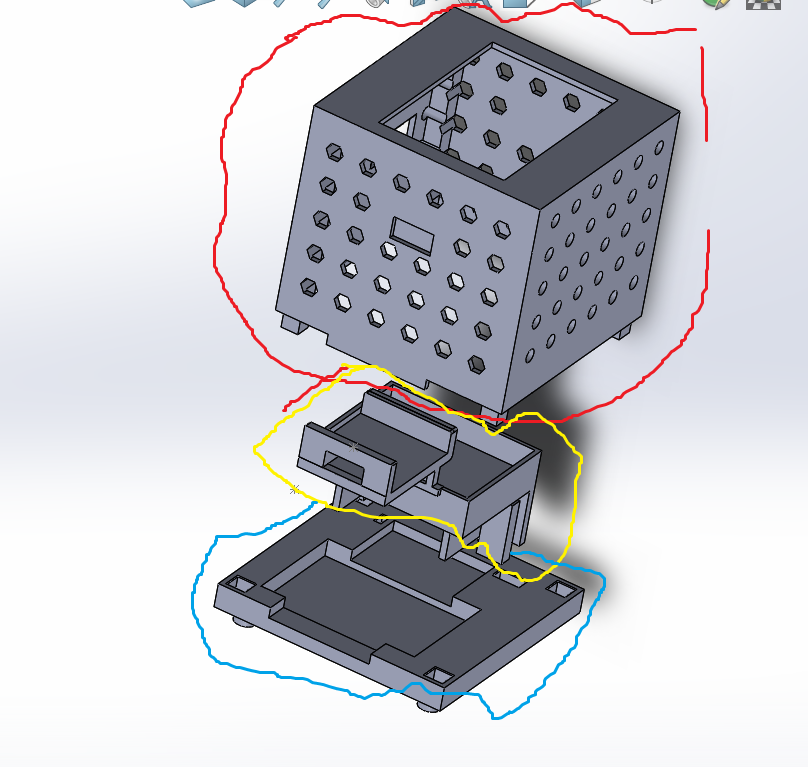
1: circled in red, is the packaging
2: circled in yellow is the location of the microcontroller and relay
3: circled in blue is the location of the power supply module
Drawing
for this part you have to select this mode when you open the new projet
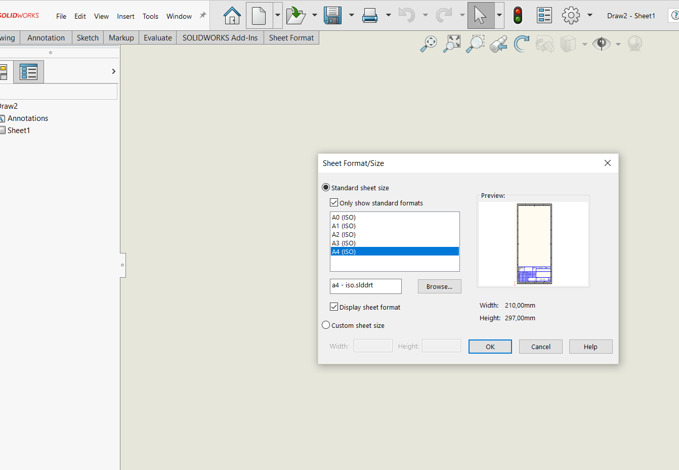
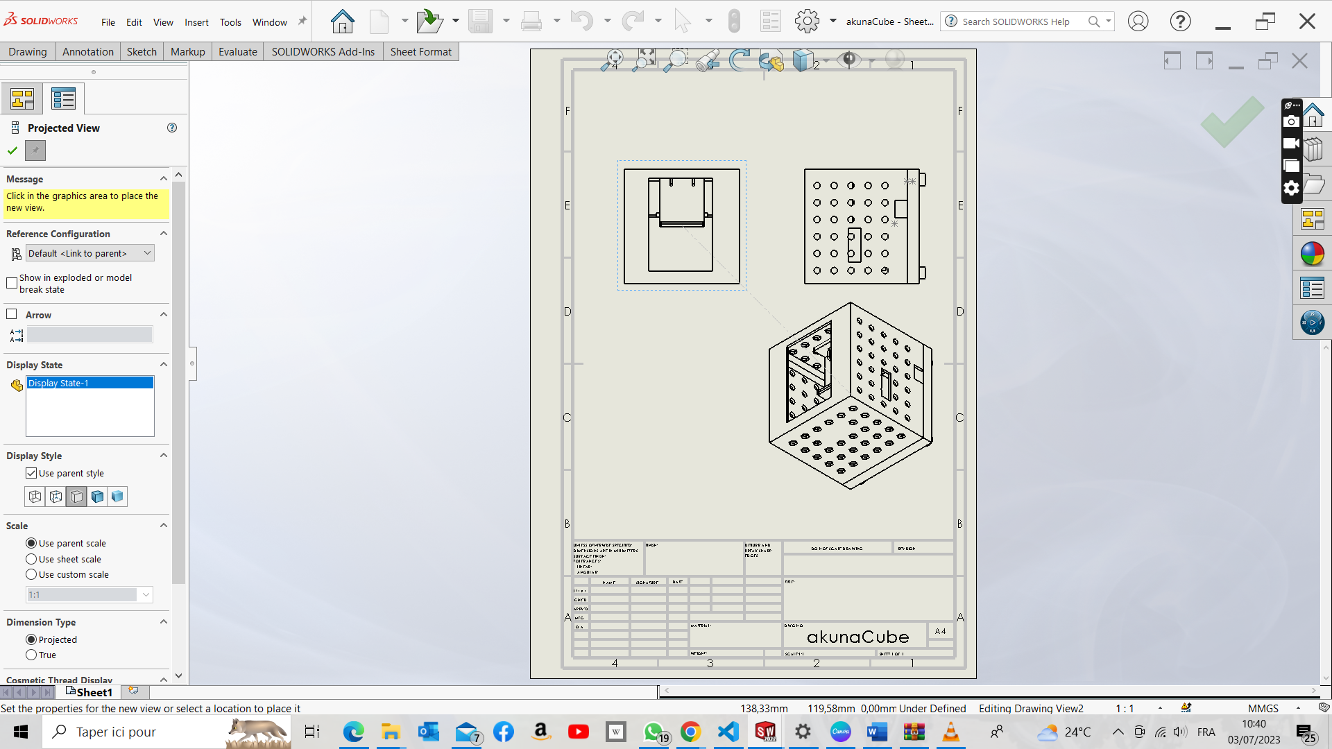
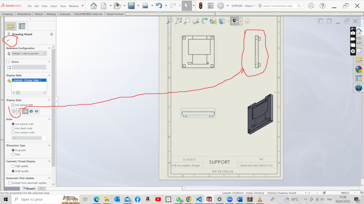
get the parts here
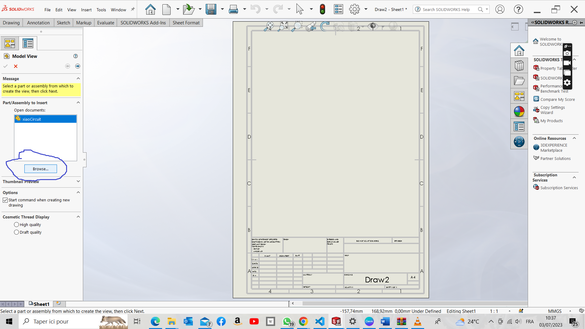
now it’s time to position the different views properly
Explaination Video