Akuna Cube Design
Akuna Cube Electronics
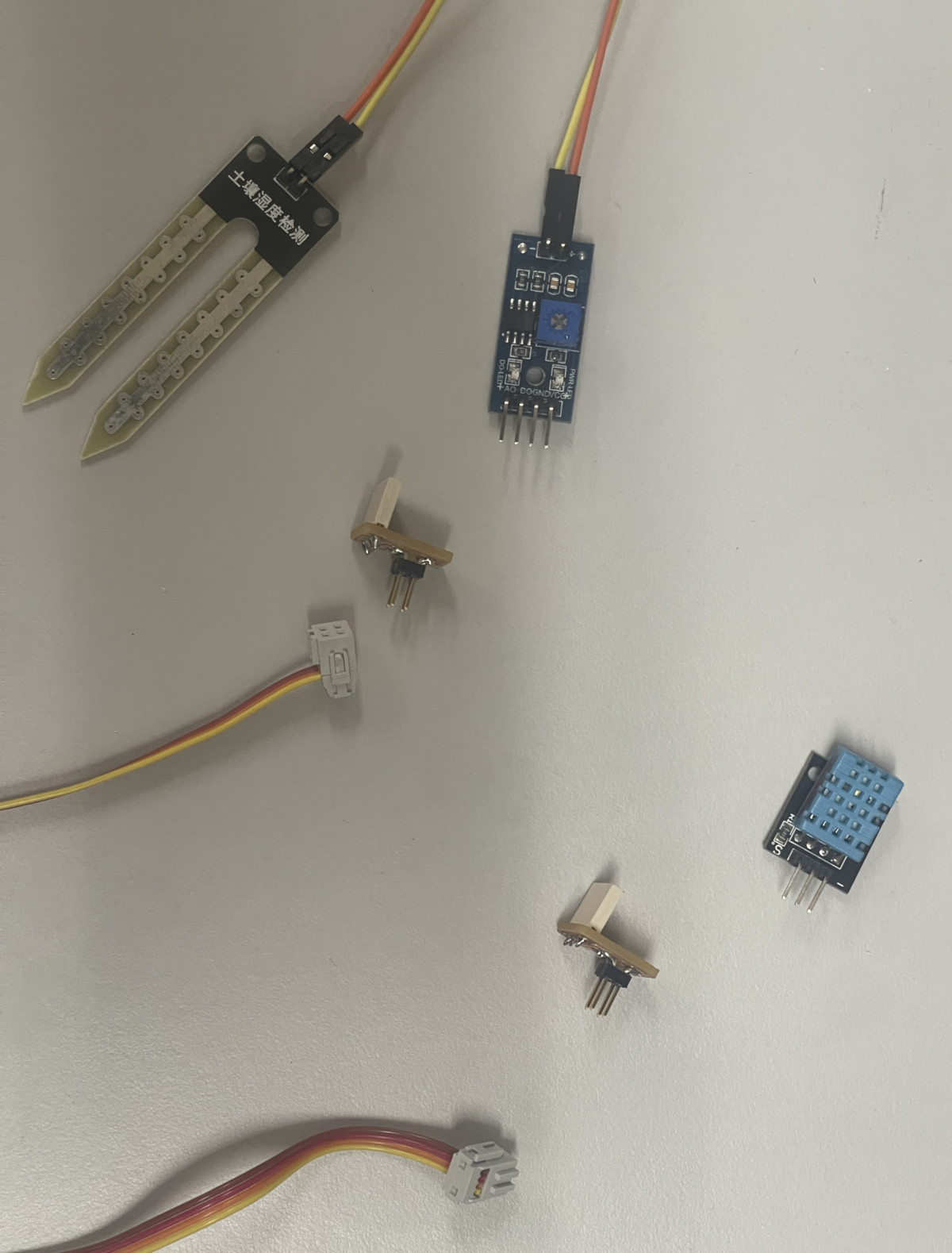
1. Electronic components and tools
Electronic Components
| Component | Origin | Price ($) | Quantity | Subtotal ($) |
|---|---|---|---|---|
| CONN HEADER SMD 4POS 2.54MM | Digikey | $0.93 | 10 | $9.30 |
| CONN RCPT 4POS 0.1 TIN SMD | Digikey | $0.70 | 10 | $7.00 |
| 6W, 2.54MM PTH SOCKET, SIL, SMT | Digikey | $0.93 | 5 | $4.65 |
| 5W, 2.54MM PTH SOCKET, SIL, SMT, | Digikey | $0.86 | 7 | $6.02 |
| 2W, 2.54MM PTH SOCKET, SIL, SMT | Digikey | $0.49 | 6 | $2.94 |
| RELAY | AKUNATEK | $4.00 | 3 | $12.00 |
| Seed studio XIAO ESP32C3 | DIGIKEY | $5.80 | 1 | $5.80 |
| DHT11 sensor | DIGIKEY | $19.00 | 1 | $19.00 |
| Raspberry Pi 4 modelB | DIGIKEY | $153.85 | 1 | $153.85 |
| Screen module | Alibaba | $130.00 | 1 | $130.00 |
Tools
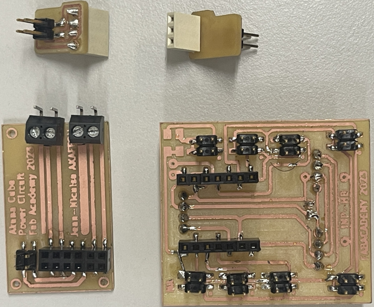
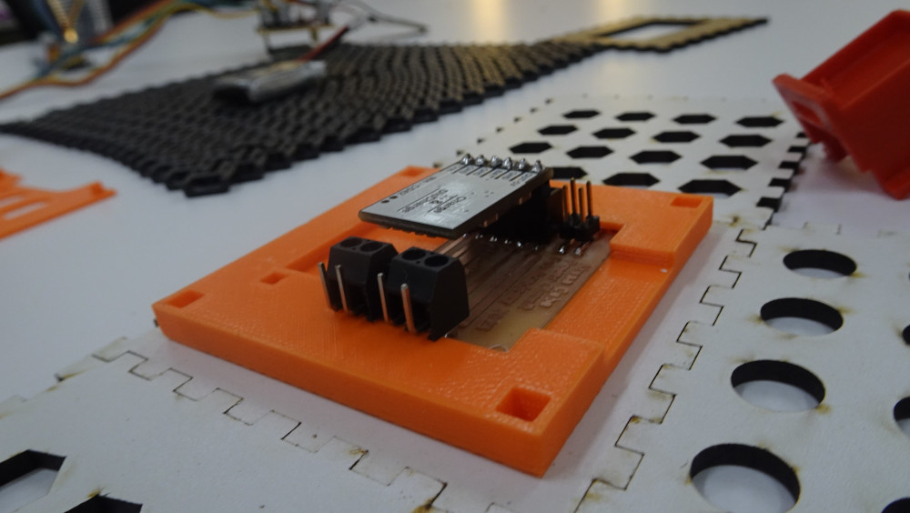
2. Electronics Design
For the electronic design of our AKUNA CUBE modules, we used two software packages: kicad and eagle. For more details, please refer to Week 6 (Electronic design).
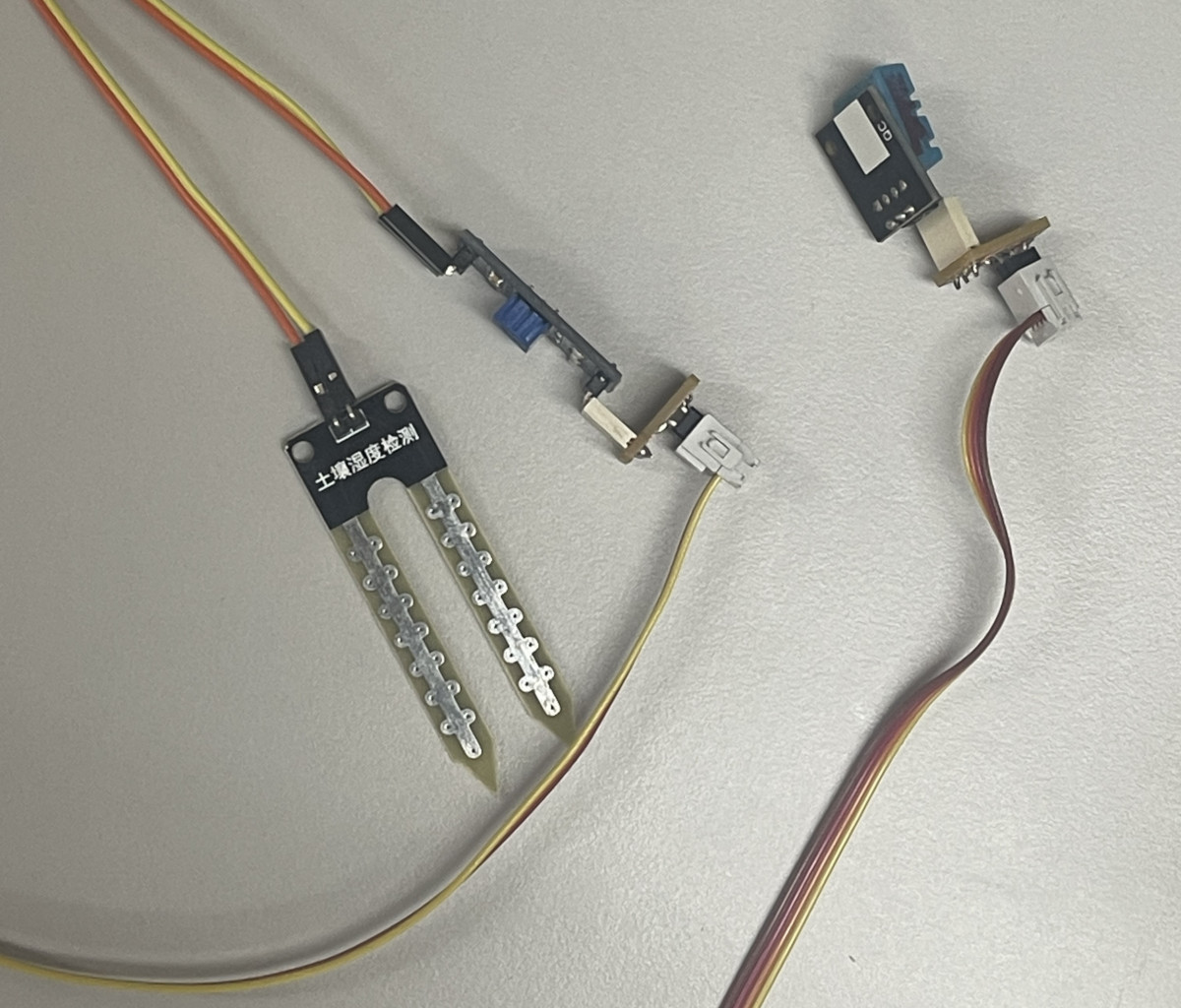
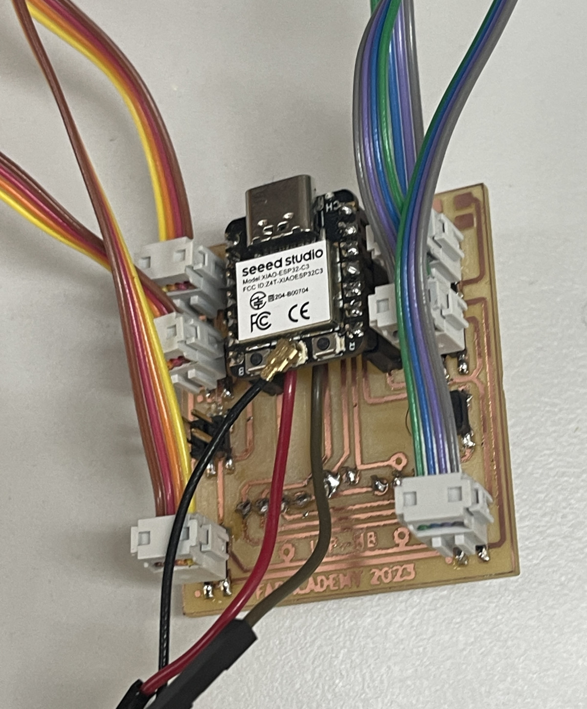
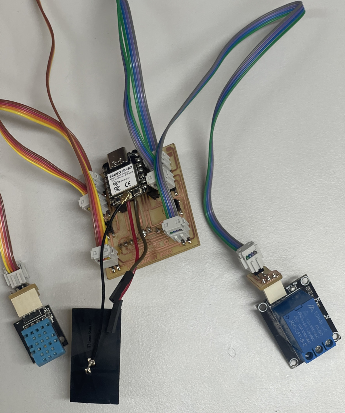
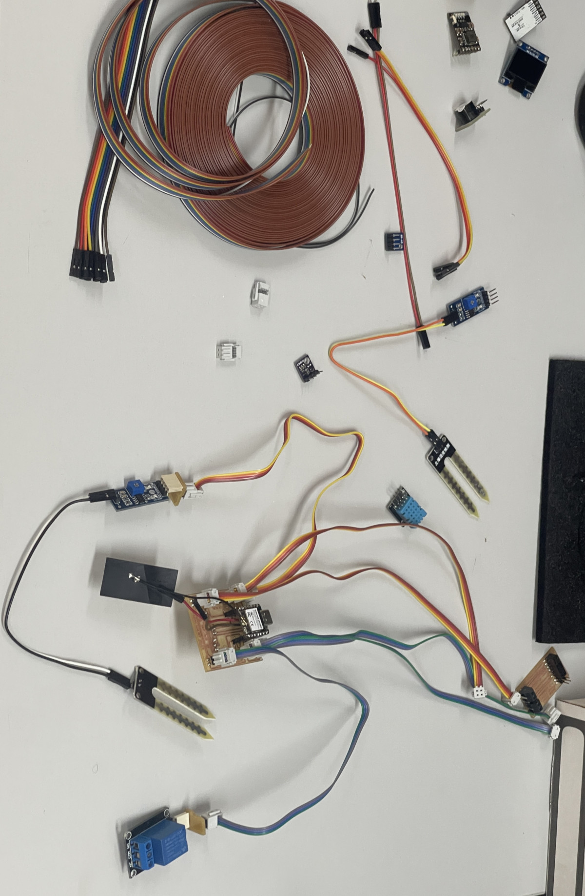
Here’s a picture of our various electronic circuits.
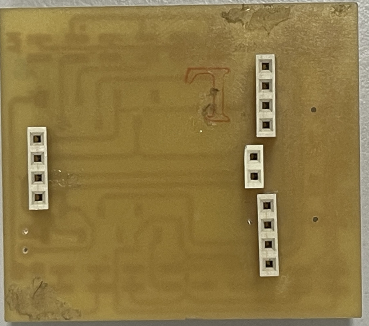
3. Electronic Production
PCB
Tools
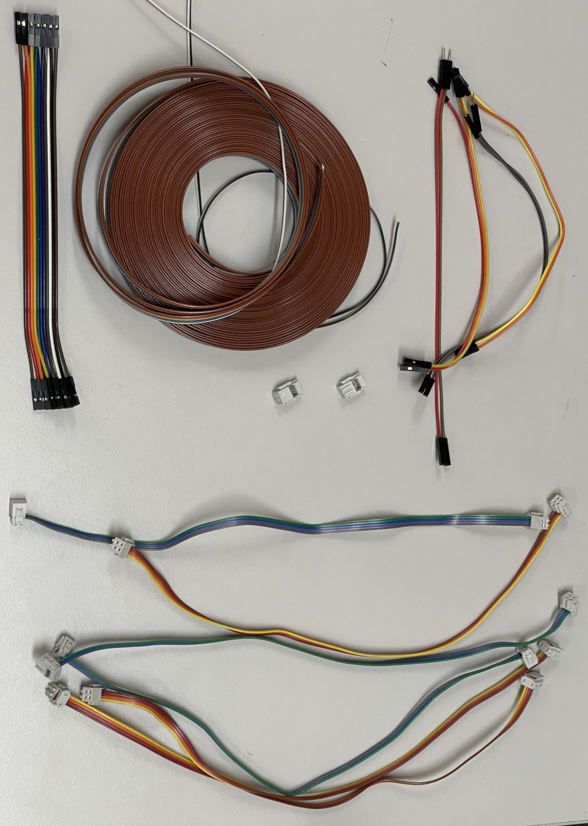
4. Electronic Wiring
5. Electronic test
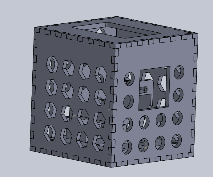
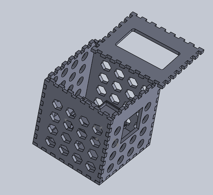
Akuna Cube Mecanic
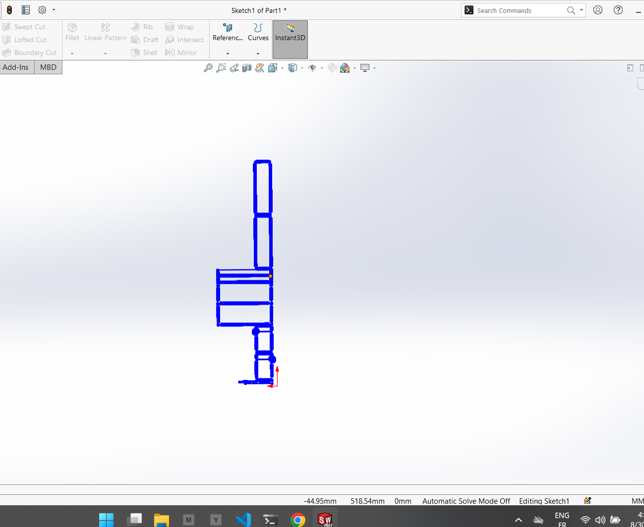
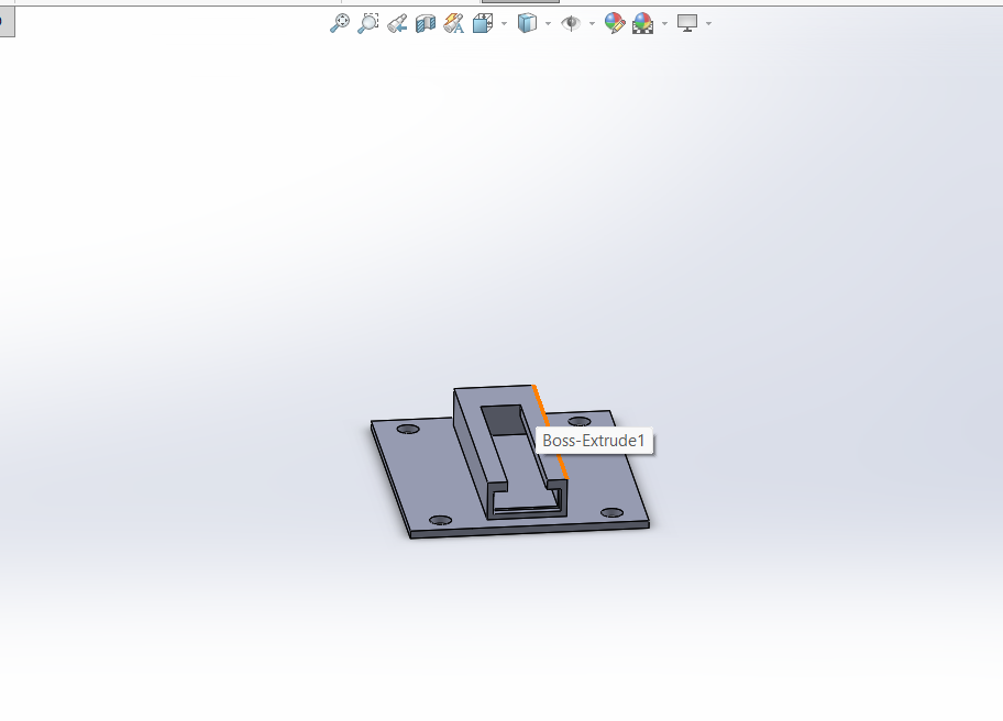
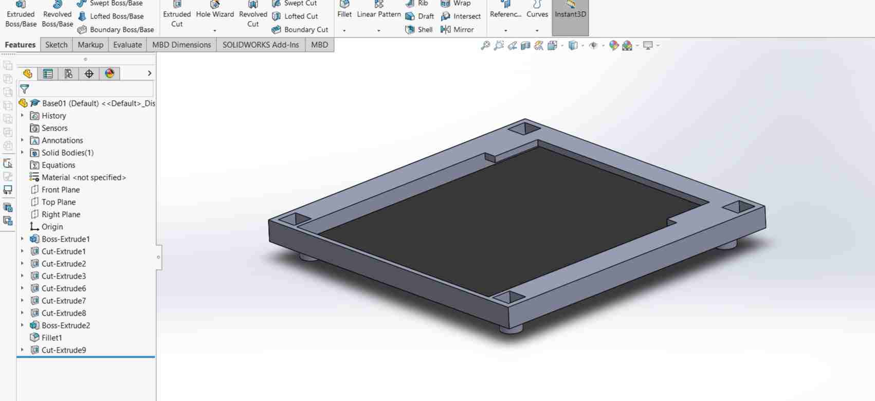
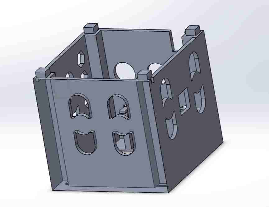
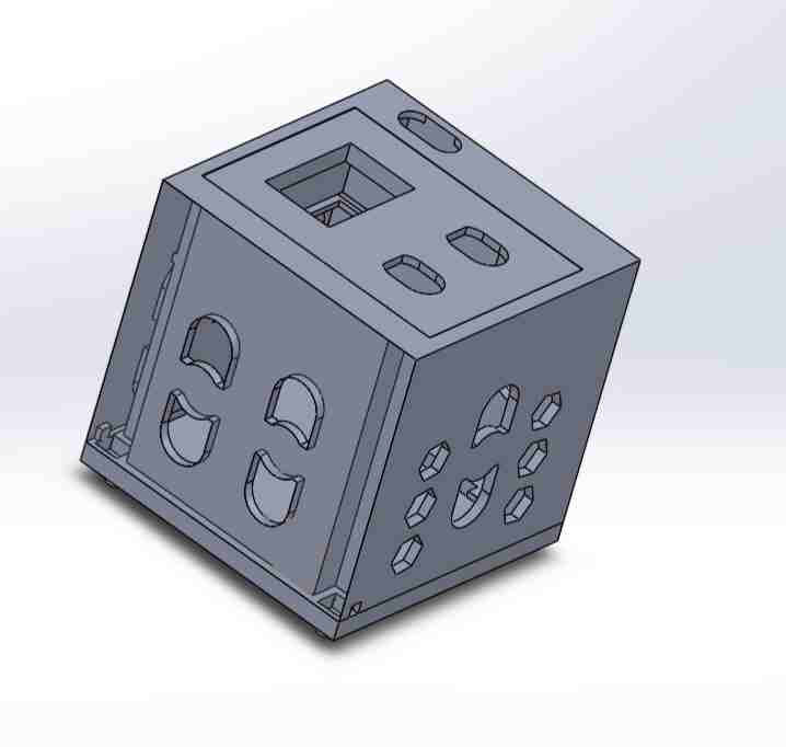
1. 3D design
- design on solidworks

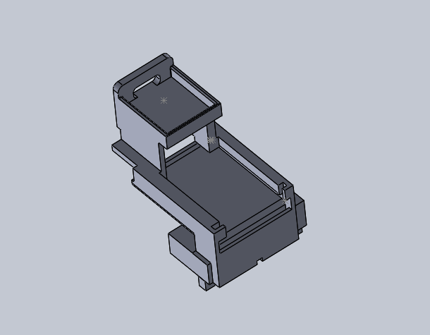
- assembly on solidworks
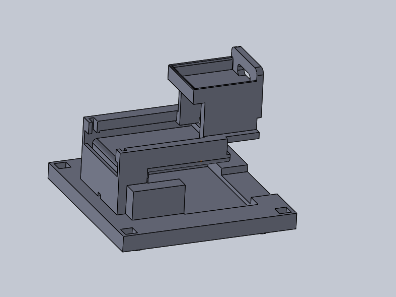
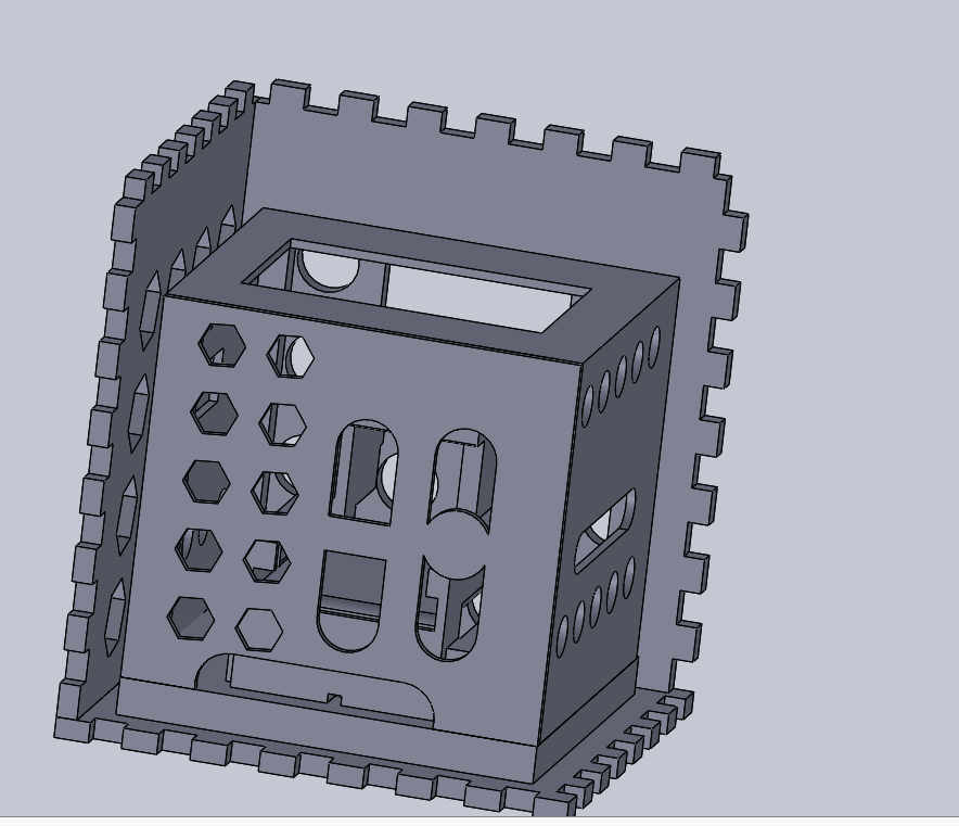
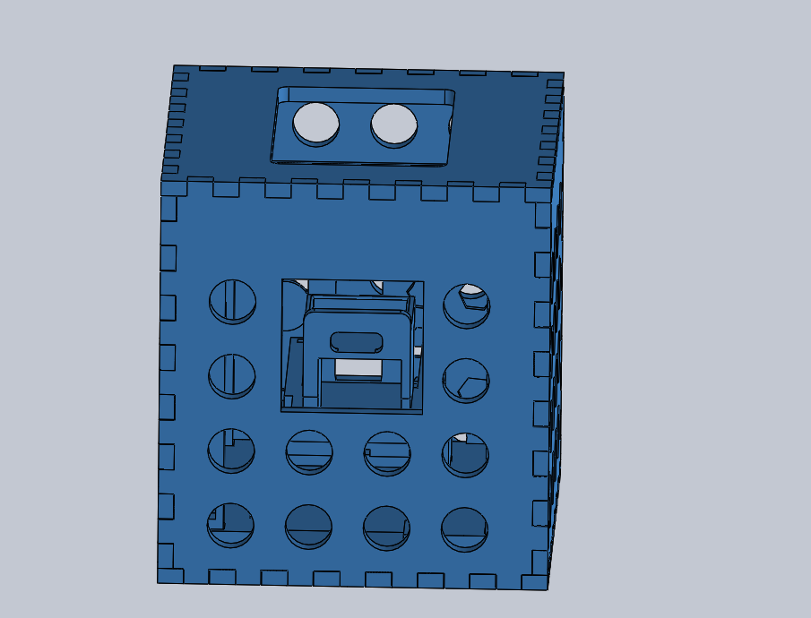
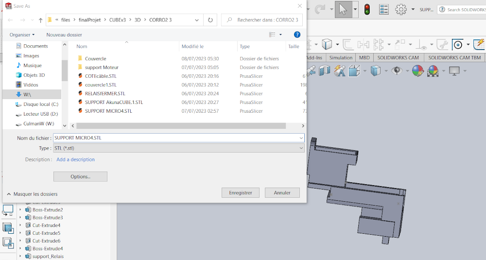
- STL fil generating
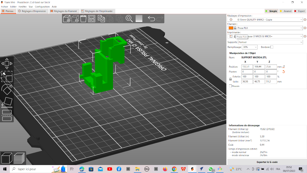
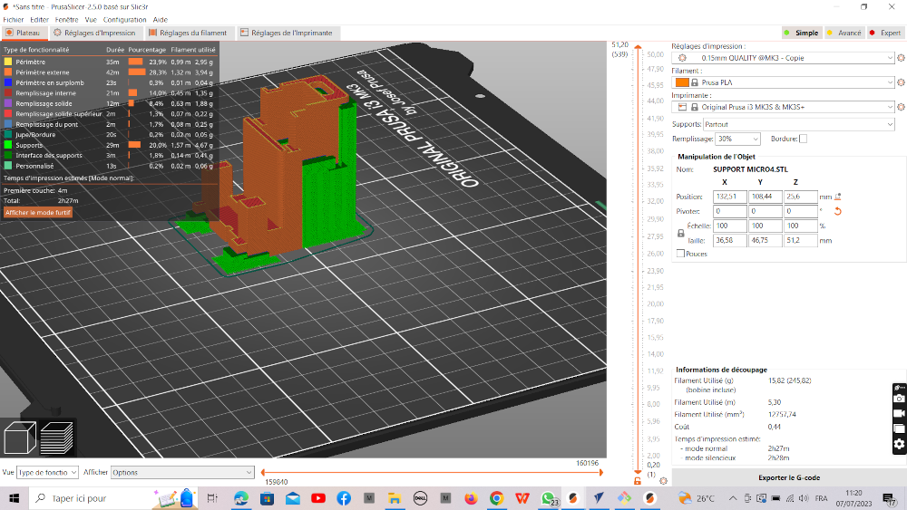
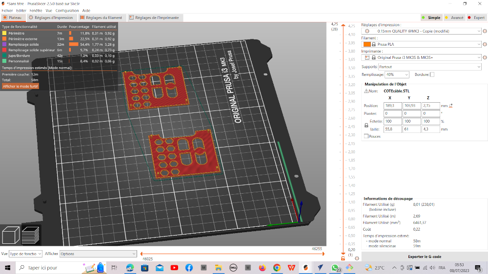
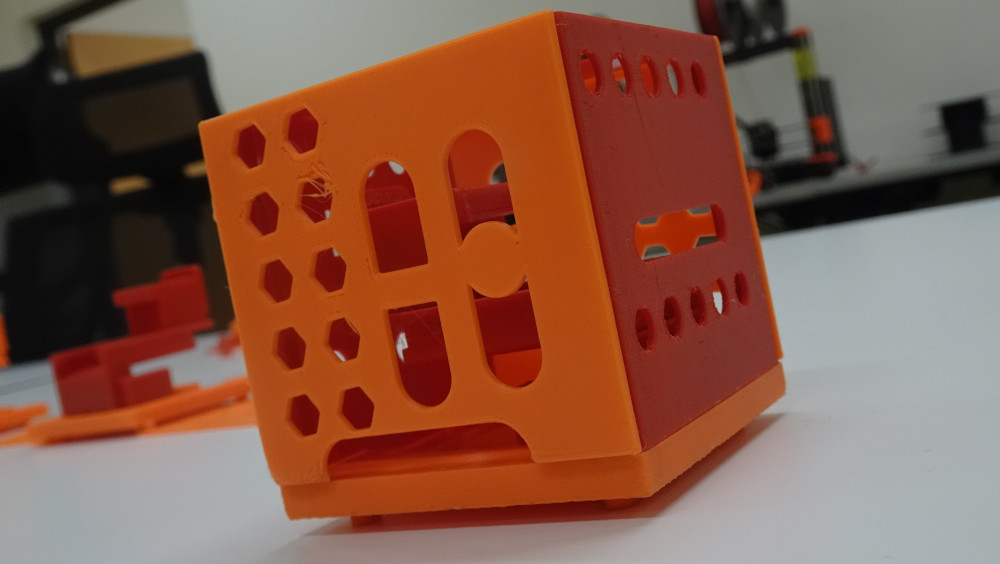
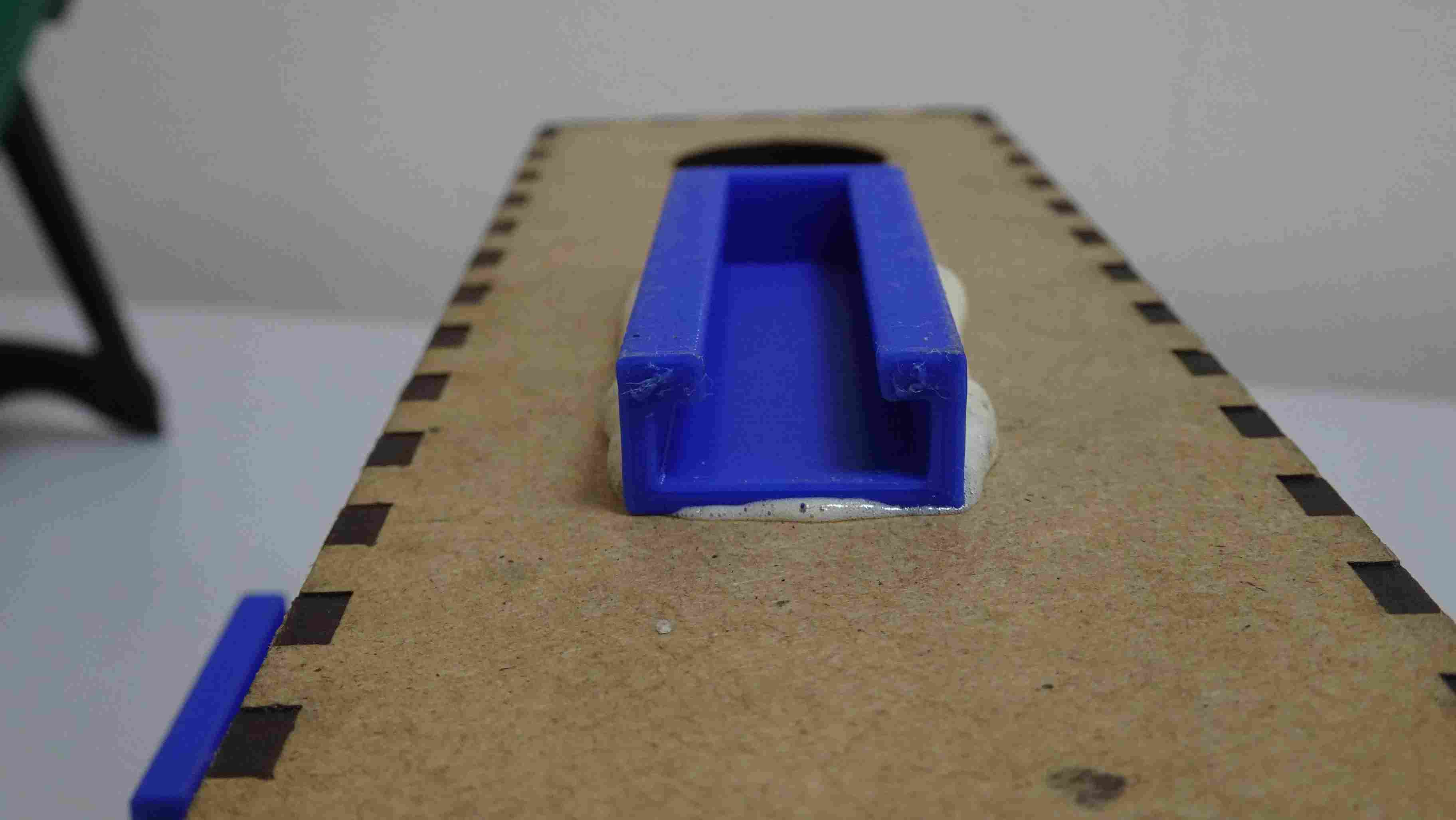
2. 3D Printing
- prusa slicer
- print component box

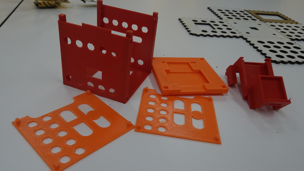
- After 3D printing

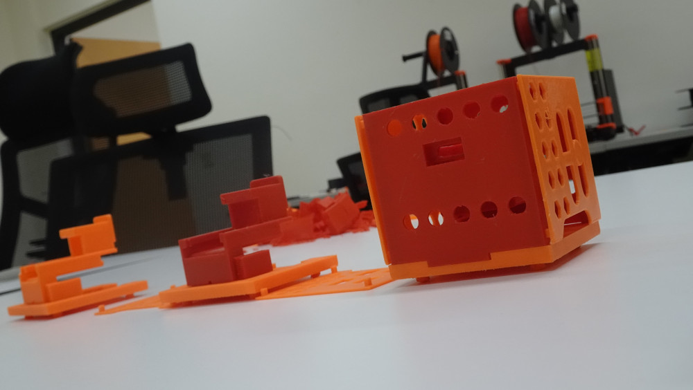
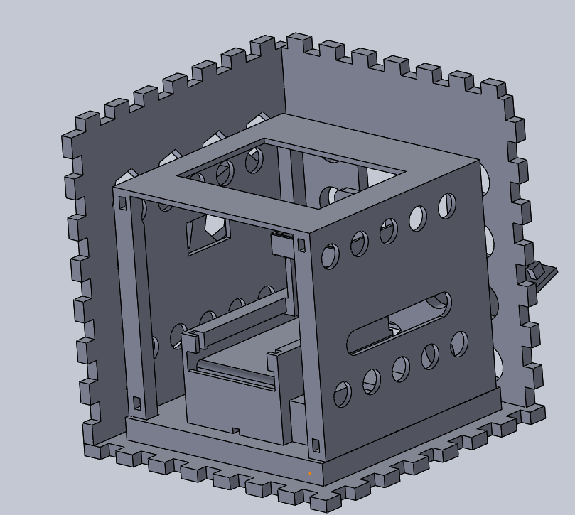
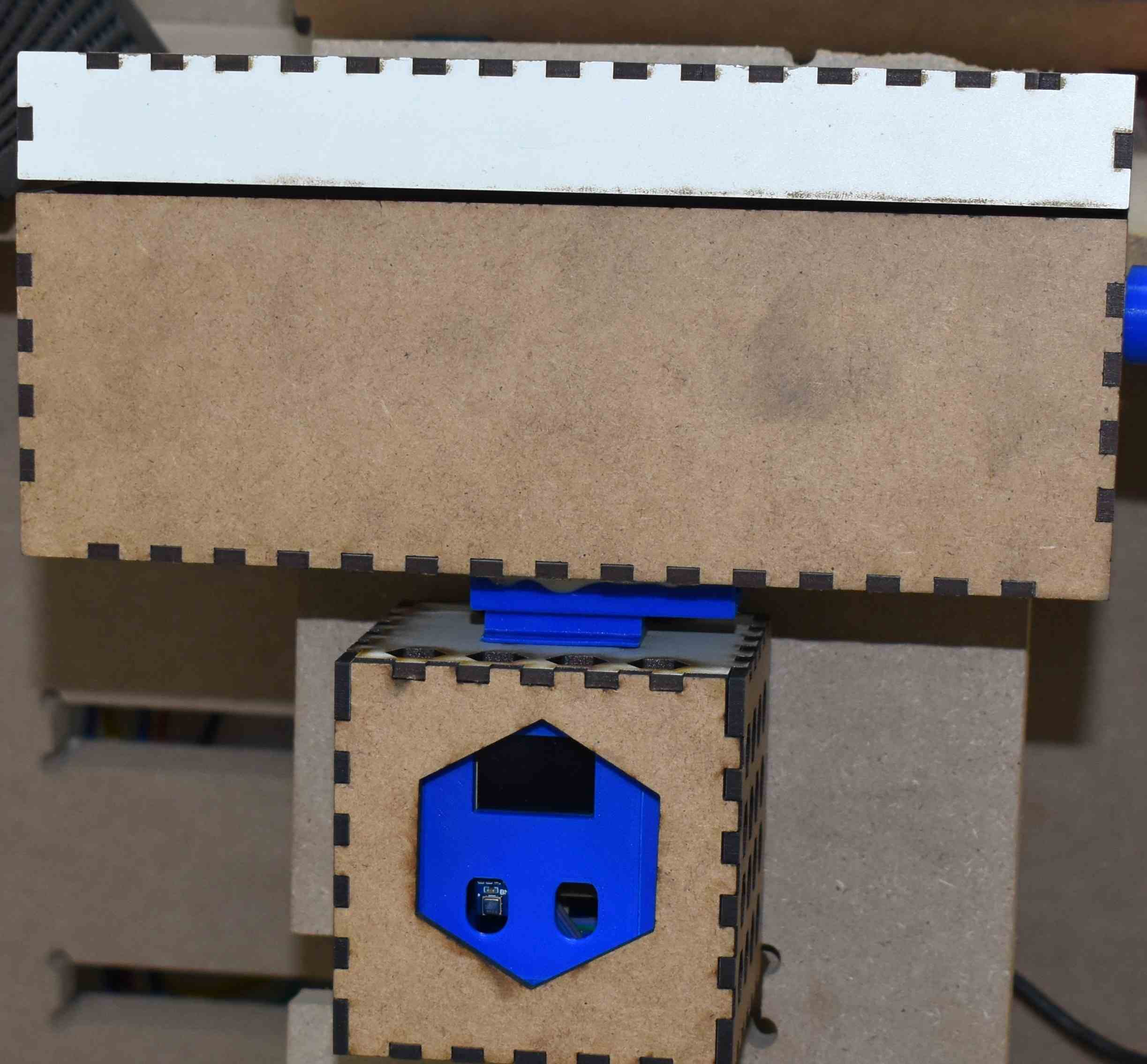
3. Assembling
- aKUNA CUBE MECHANICAL ASSEMBLY

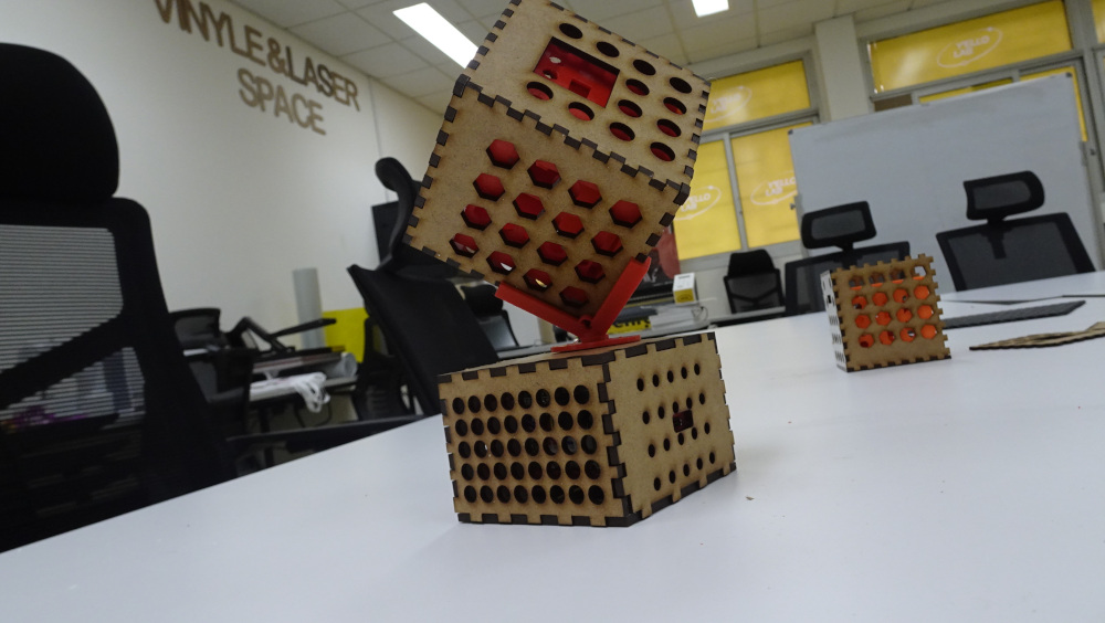
- CUBE PRESENTION PLATFORM
FOR THE PRESENTATION OF MY PRODUCT I MADE A ROTATING PRESENTATION PLATFORM
- MODELING REMAINS THE SAME AS FOR PACKAGING
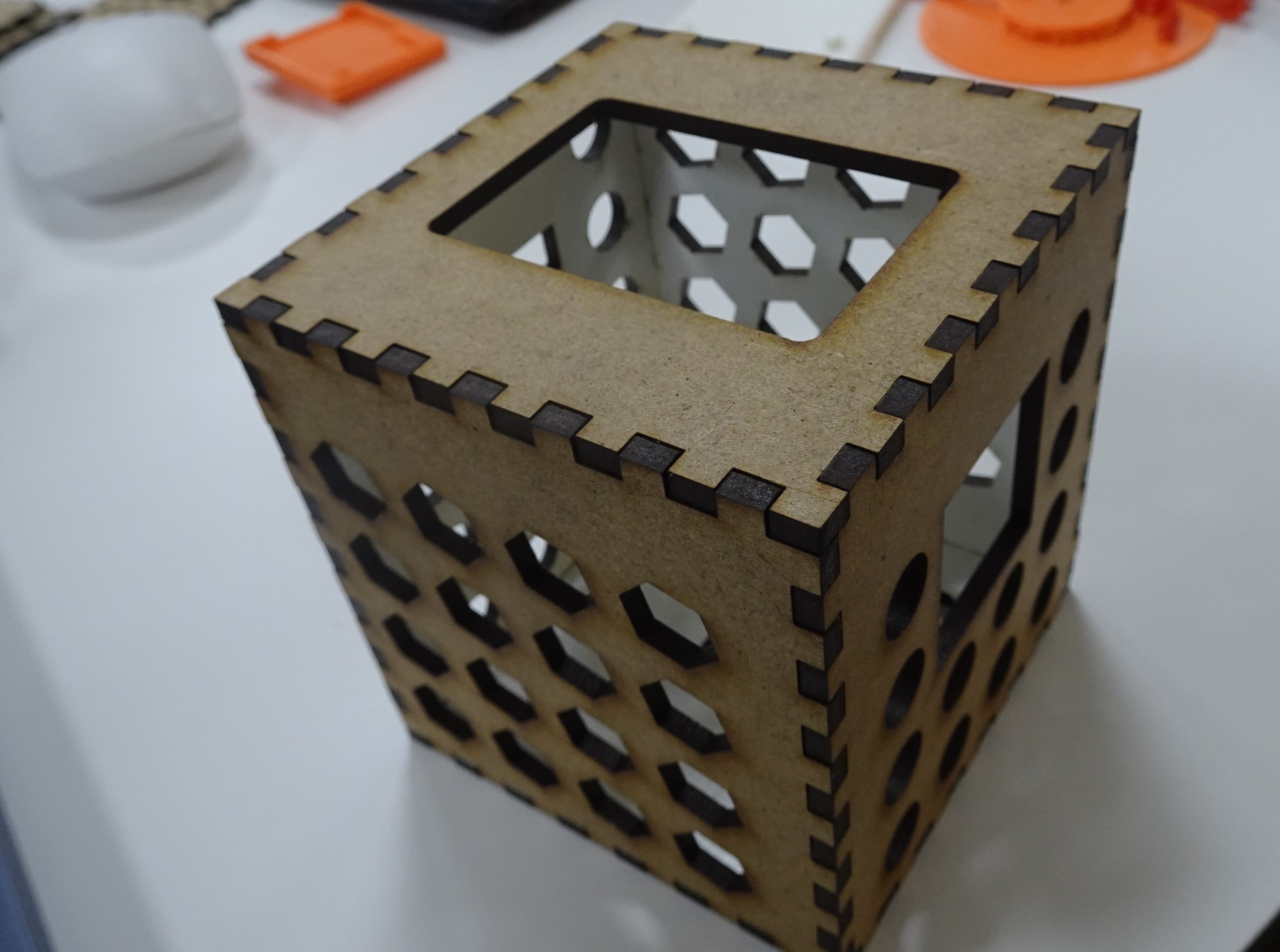
After printing and cuttind we move to assembly.


- AKUNA CUBE MECHANICAL FILES
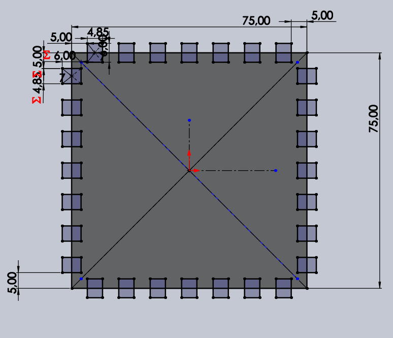
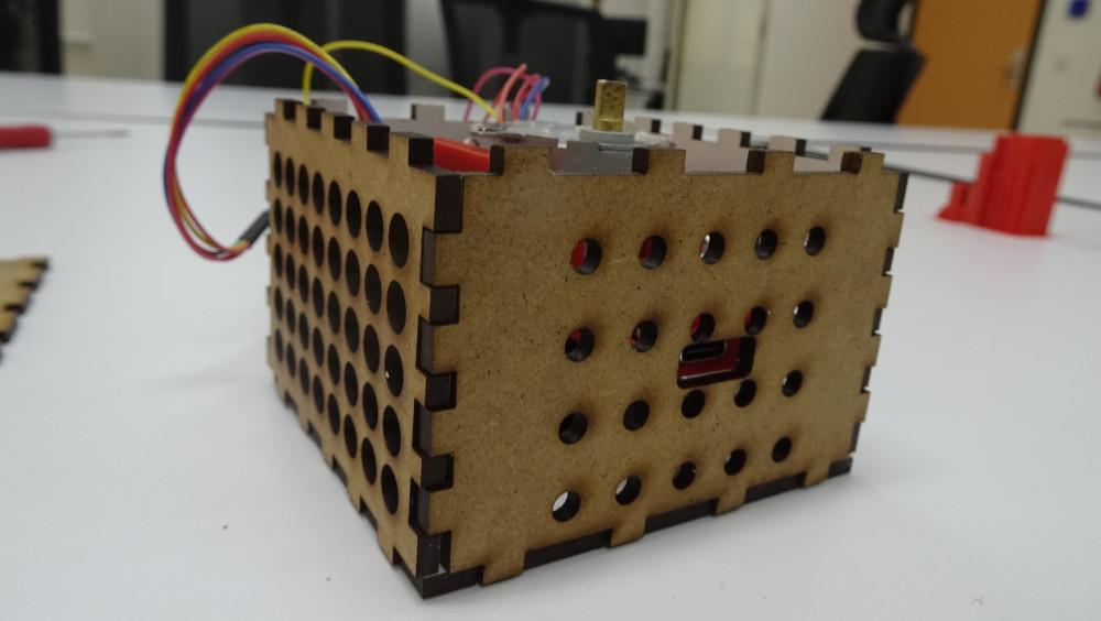
Akuna Cube Packaging
1. presentation
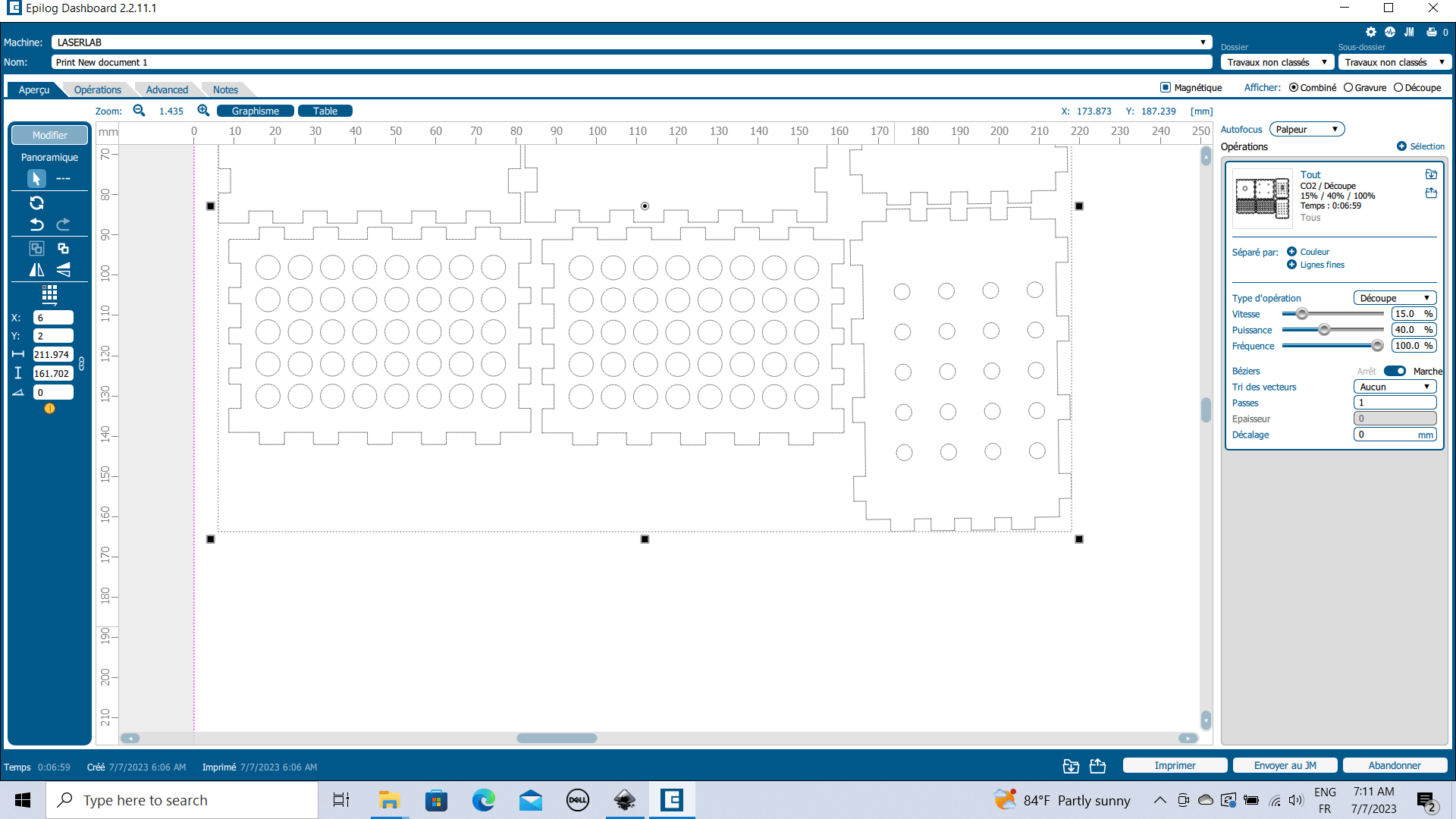
Since our AKUNA CUBE data collar system is designed to be installed in extreme conditions, we have designed a cube-shaped packaging to protect it and make it more resistant. You’ll find below the results of the design of this packaging, which we created using SolidWorks software. For more details, please refer to Week 3 (Computer controlled cutting).
2. Procedure
- 2D Design on solidWorks

- 3D Design on SolidWorks
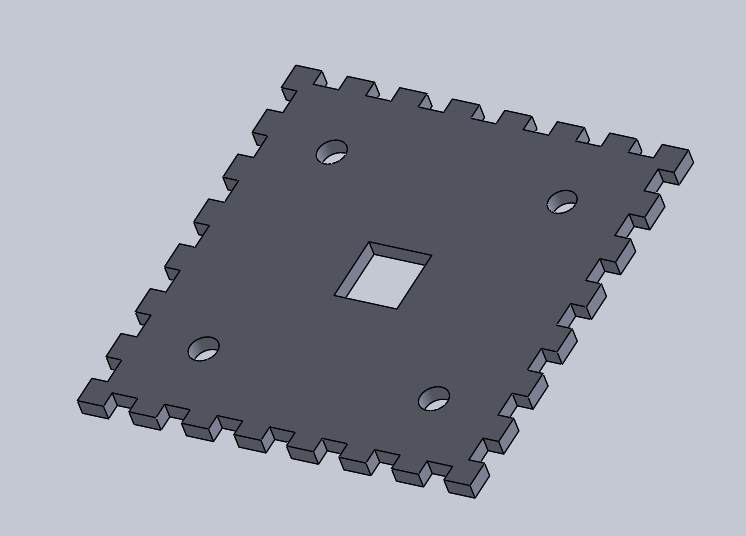
- assembly on solidWorks
- DXF files Saving
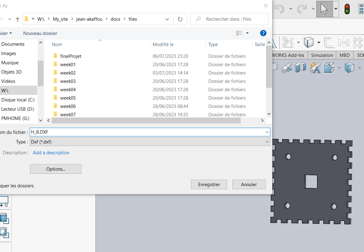
3. Production
- Inkscape

- laserCutting
- ON MACHINE
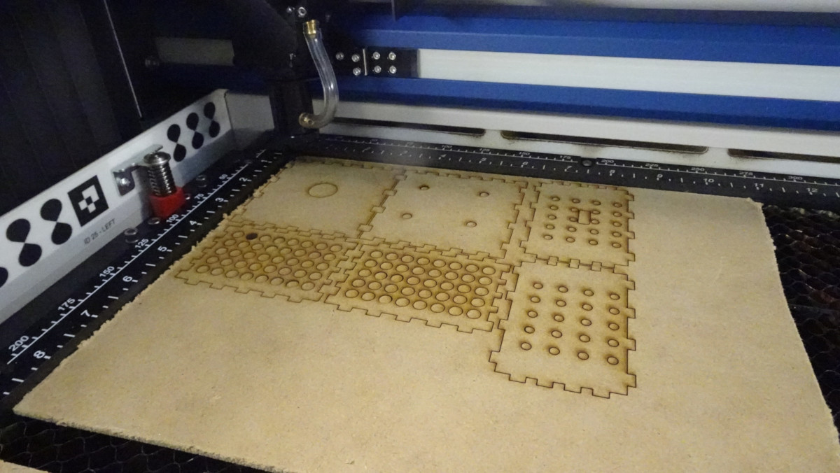
- during
- 4 Heros
4. Files
Akuna Cube Interface
To design the human-machine interface for our final project, we used several solutions, including :
1. Oled interface
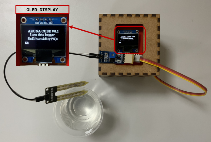
As our data collection cube is equipped with an oled screen, we chose to display sensor values and action status directly on the oled screen.
Here’s an example:
Here we have a cube equipped with a soil moisture sensor and a relay.
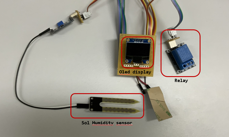
As shown below, we have the value of the humidity sensor on the OLED screen.
To program the cube, we used the Arduino IDE.
Here’s the program.
| Akuna_cube_1.ino | |
|---|---|
1 2 3 4 5 6 7 8 9 10 11 12 13 14 15 16 17 18 19 20 21 22 23 24 25 26 27 28 29 30 31 32 33 34 35 36 37 38 39 40 41 42 43 44 45 46 47 48 49 50 51 52 53 54 55 56 57 58 59 60 61 62 63 64 65 66 67 68 69 70 71 72 73 74 75 76 77 78 79 80 81 82 83 84 85 86 87 88 89 90 91 92 93 94 95 96 97 98 99 100 101 102 103 104 105 106 107 108 109 110 111 112 113 | |
2. Screen interface
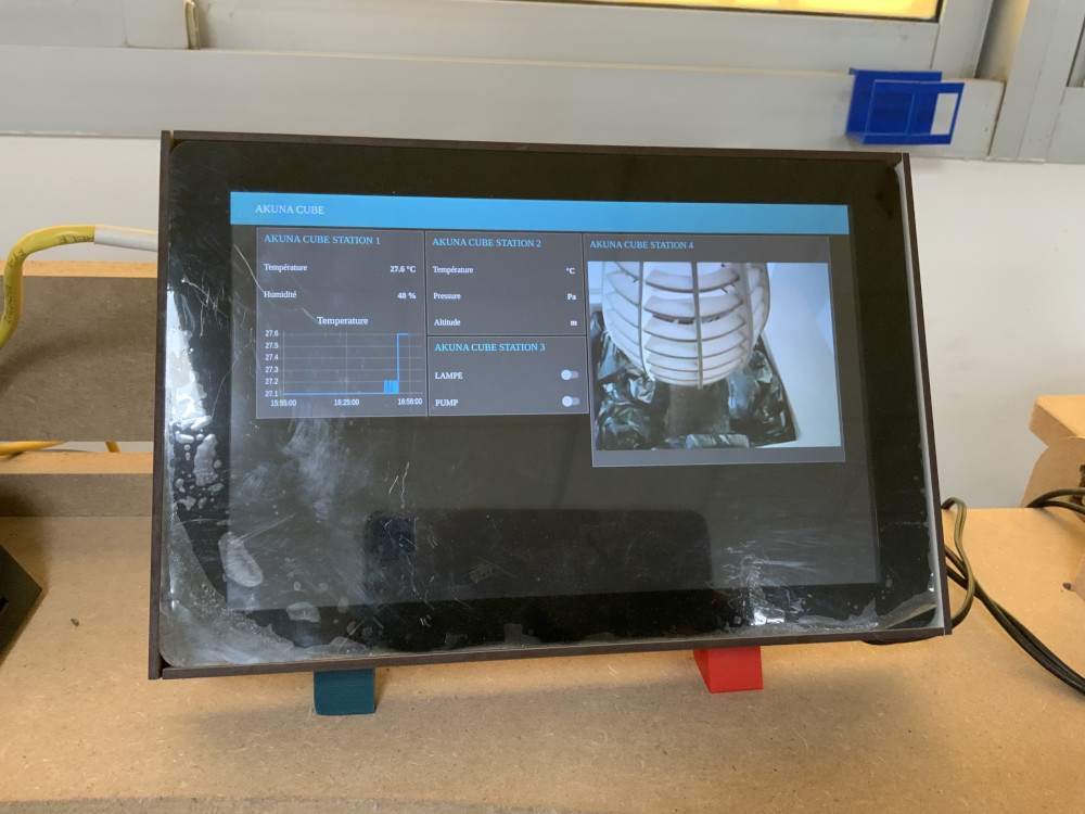
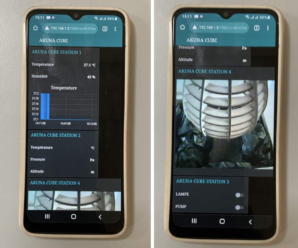
Since our system is equipped with several Akuna cubes that collect data and control actuators, we decided to develop a human-machine interface to display all the sensor values of each AKUNA CUBE and control all the actuators.
To create this HMI we proceeded as follows:
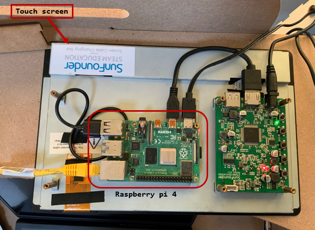
- We chose to use a Raspberry pi with a touch screen as shown below.

-
On the Raspberry pi we installed Node Red to build the HMI and mosquitto as an MQTT server for communication and data collection from the AKUNA CUBE. For more information please refer to the web pages of Week 13 (Networking and communications) and Week 14 (Interface and application programming).
-
To protect the touchscreen connected to the Raspberry, we cut out a housing as shown below.
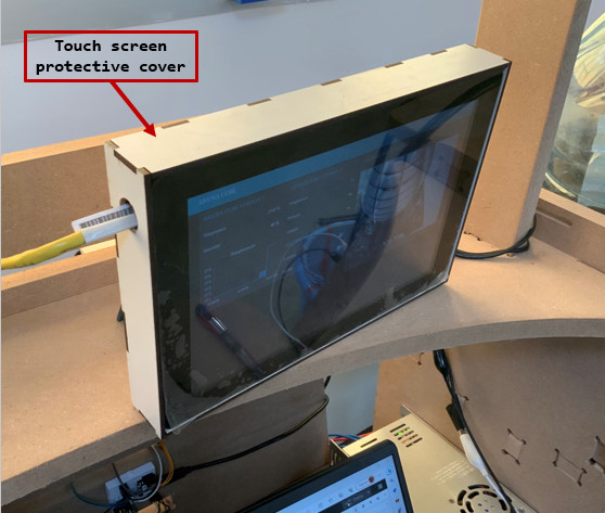
- Once the case was mounted on the screen, we connected it to a WiFi router to enable it to communicate with the other modules via WiFi.
Here’s the final result of the HMI.
HERO video
3. Mobile phone Interface
Since the graphical interface we’ve developed using the Node Red solution is a web page hosted on a web server installed on the Raspberry pi we’ve chosen, all we have to do is enter the URL address corresponding to the web page in a browser to access it.
To access the HMI with a smarphone, we followed the procedure below:
- we connected to our system’s wifi network.
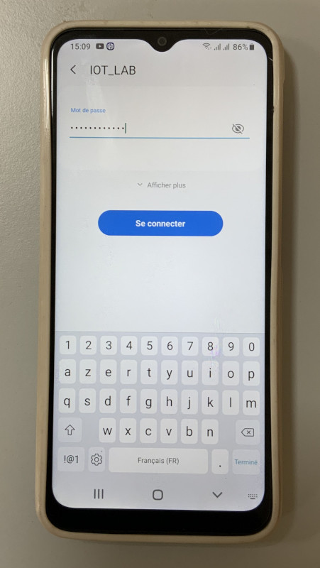
- we opened the google chrome browser on our smartphone.

- we entered the URL address of our HMI page: 192.168.1.3:1880/ui

- here’s the interface displayed on our smartphone
Akuna Cube System integration
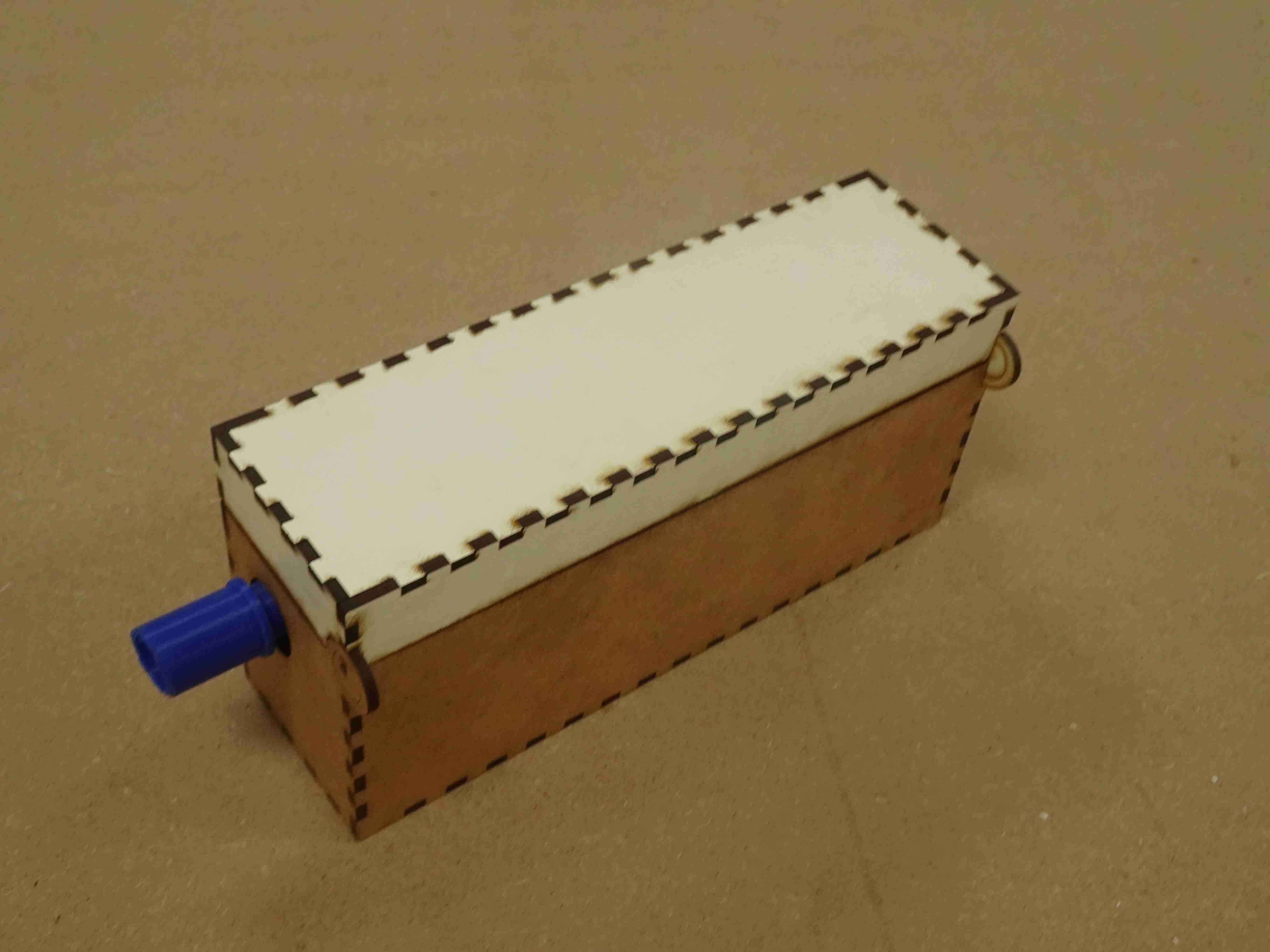
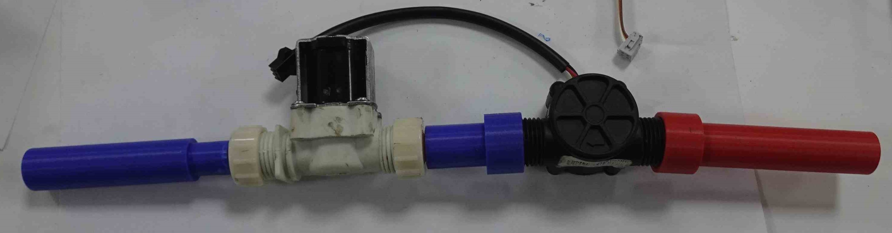
I changed the design a bit because I made a modification to my circuit.

I put my electrovane and my flowmeter in a box so I could hang it up.
-
-
-

-
-
-

-
-

-
-
-
Electrovane and dembimeter connection
-
-
-
## Akuna Cube Table


-
Akuna Cube Assembly