04. Embedded Programming
Part one : Assignment
-
Groupe assignment
- Compare the performance and development workflows for other architectures.
- Document your work to the group work page and reflect on your individual page what you learned.
-
Individual assignment
- Browse through the datasheet for your microcontroller.
- Program a microcontroller delevopment board to interact and communicate.
-
Task
- Linked to the group assignment page
- Document what you learned from browsing through a microcontroller datasheet.
- Programmed your board to interact and communicate.
- Described the programming process(rd) you used .
- Included your source code
- Included ‘hero shot(s)’
Part two : Groupe assignment
To see our group assignment click here
Part three : Individual assignment
1. What is Embedded system
1.1. Embedded system
An embedded system provides support for sensor interfacing, processing, storing, and/or controlling to facilitate compact and customized solutions. Embedded systems have wide range of applications such as entertainment, communication, security, and automobile.
1.2. Embedded System Applications
They are present everywhere. Doesn’t believe it? Most of people use without knowing them.

1.3. What is embedded hardware?
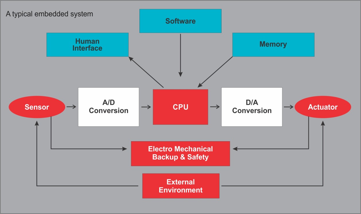
The basic hardware components of an embedded system shown in a block diagram in Fig 1.1 These include the processing unit, sensors and actuators, ADC, DAC, I/O unit and the memory block. The processing unit could be a microprocessor, a microcontroller, FPGA i.e. field programmable gate array or ASIC (Application Specific IC) depending on the application requirements. Sensors such as sound sensor, ambient temperature sensor, motion sensor etc. are generally analog in nature since they sense the data from outside world. This data is converted from analog to digital and sent to a processing unit, post which required action is performed by actuators
1.4. What is embedded software?
The following four components typically make up an entire embedded software suite:
Firmware. This is a built-in program written for specific hardware.
Operating system. This is the software used for setting rules and controlling system resources. It includes device drivers that provide an application programming interface (API) for upper software components and makes them communicate with hardware parts. Operating systems can either be general-purpose or real-time.
Middleware. This is a mediator that enables communication between upper and lower software levels. Middleware is created for a definite operating system and lies between an OS and application software.
Application software. This is the software that directly performs the system’s functions and interacts with end users.
All these components are included in large, complex embedded systems, although basic embedded solutions could be missing some software elements, such as an operating system.
2. What is Embedded Programming or Embedded system Programming
2.1.Embedded Programming or Embedded system Programming
Embedded systems programming, also known as embedded programming, facilitates the development of consumer-facing devices that don’t use conventional operating systems the way that desktop computers and mobile devices do.
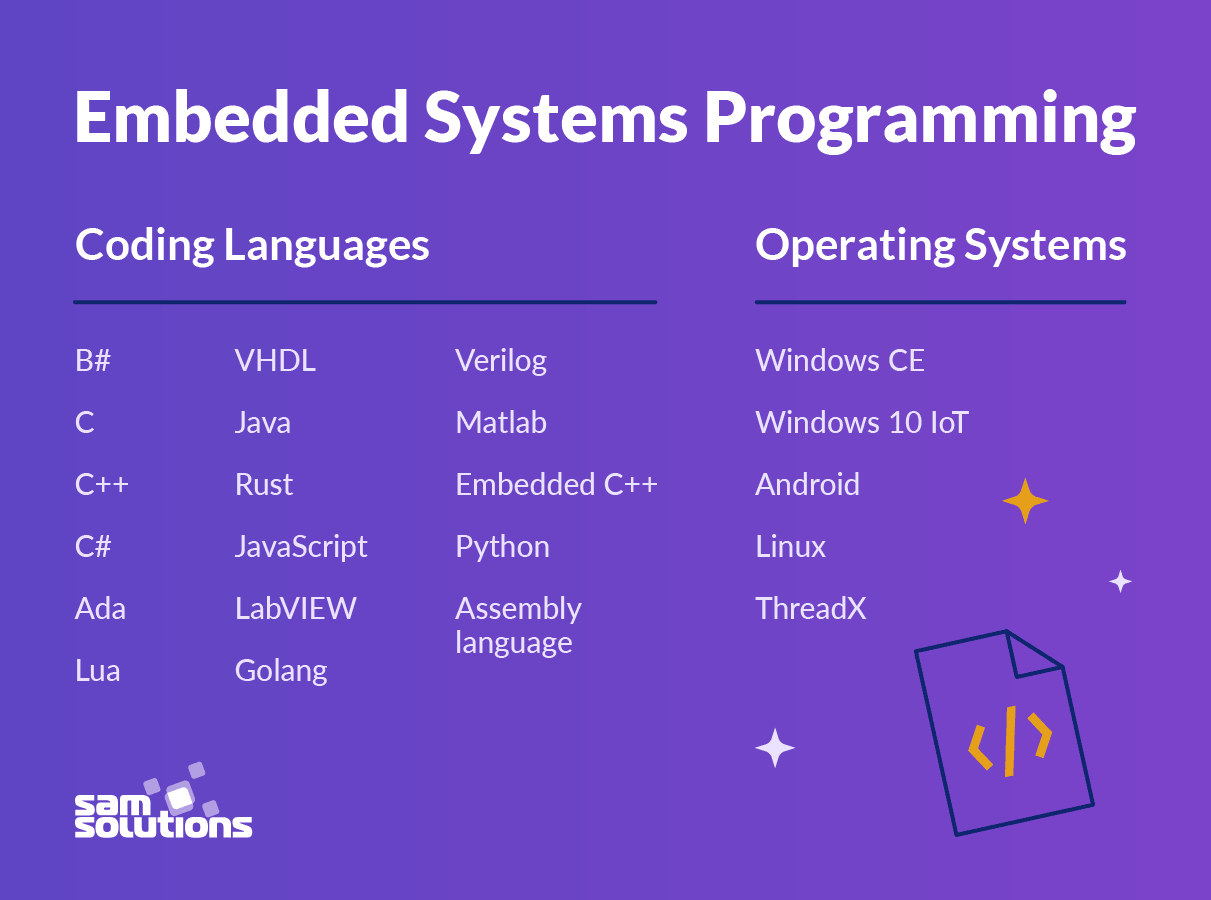
2.2.Best Languages and OS for Embedded Systems Programming
Embedded systems can be programmed using different programming languages like Embedded C, Embedded C++, Embedded Java, and Embedded Python. However, it entirely depends on the developer to use which programming language for the development of the embedded systems.
3. Embedded programming with C language:Seeed Studio XIAO ESP32C3
3.1. What is Seeed Studio XIAO ESP32C3
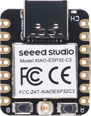
Seeed Studio XIAO ESP32C3 is an IoT mini development board based on the Espressif ESP32-C3 WiFi/Bluetooth dual-mode chip. ESP32-C3 is a 32-bit RISC-V CPU, which includes an FPU (Floating Point Unit) for 32-bit single-precision arithmetic with powerful computing power.
To learn more read the datasheet
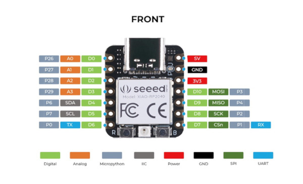
3.1.1. Pinout reference
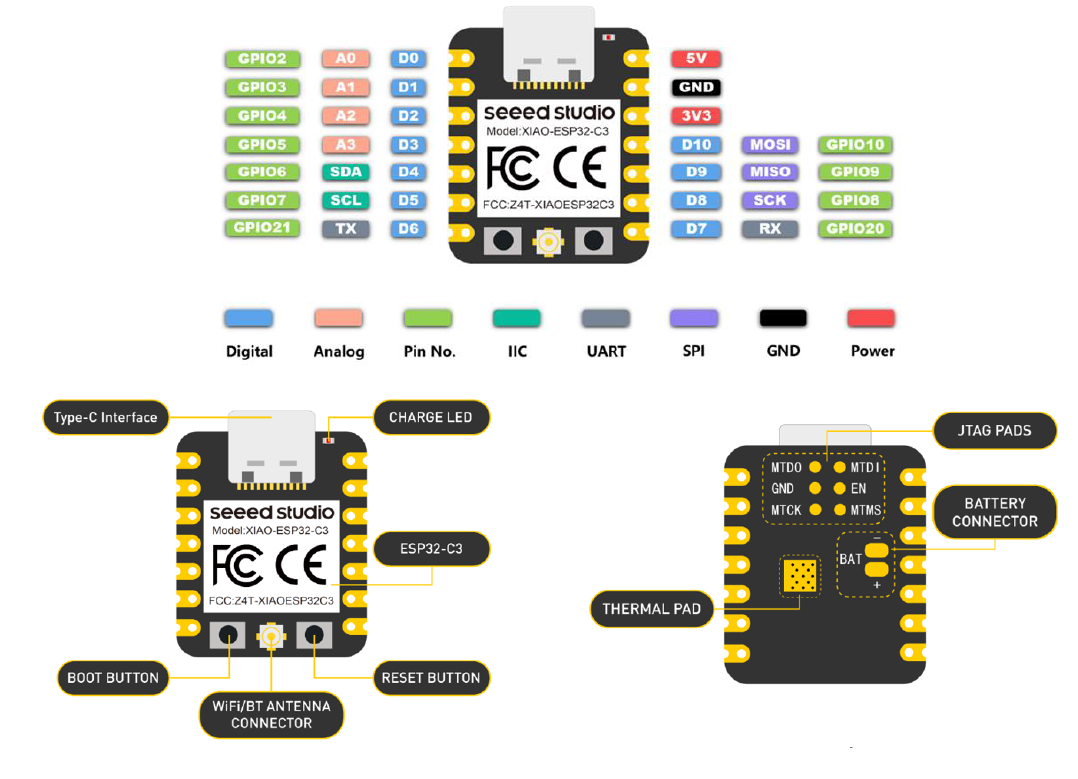
3.1.2. Power Consumption, Operating Voltage and Charging Current
Power Consumption: Low power model: <44uA Normal: 25.7mA
Operating Voltage: Type C: 5V Battery: 3.7V Li-ion
Charging Current : 380mA±30mA
3.2. How to programm Seeed Studio XIAO ESP32C3 ?
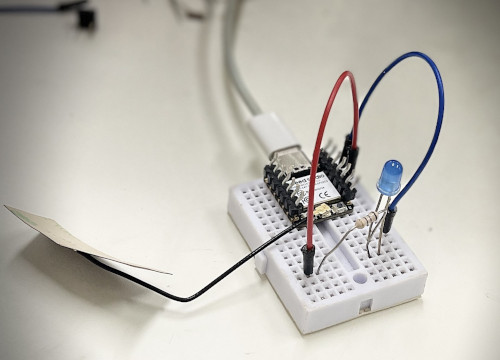
First, we are going to connect XIAO ESP32C3 to the computer, connect an LED to the board and upload a simple code from Arduino IDE to check whether the board is functioning well by blinking the connected LED.
3.2.1. Hardware setup
You need to prepare the following:
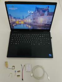
1 x Computer
1 x USB Type-C cable
1 x Seeed Studio XIAO ESP32C3
1 x LED blue
1 x Resistor 190Ω
1 x cable
1 x connector
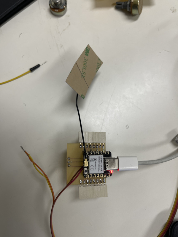
Step 1. Use the connector to fix ESP32-C3 on the breadboard.
Step 2. Connect a resistor to D10 pin via a small cable.
Step 3. Connect another resistor pin to LED pin named Cathode directly.
Step 4. Connect a LED pin named anode to GND pin via a small cable.
3.2.2. Software setup
Step 1. Download and Install the latest version of Arduino IDE according to your operating system here
Step 2. Launch the Arduino application
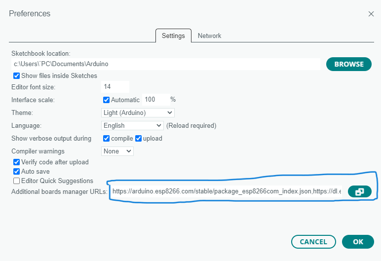
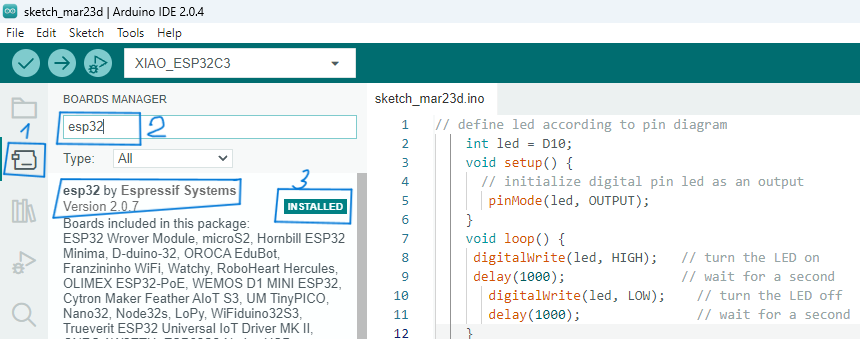
Step 3. Add ESP32 board package to your Arduino IDE
Navigate to File > Preferences, and fill “Additional Boards Manager URLs” with the url below:
https://raw.githubusercontent.com/espressif/arduino-esp32/gh-pages/package_esp32_dev_index.json
Navigate to Tools > Board > Boards Manager…, type the keyword “esp32” in the search box, select the latest version of “esp32”, and install it.
Step 4. Select your board and port
-
Navigate to Tools > Board > ESP32 Arduino and select “XIAO_ESP32C3”. The list of board is a little long and you need to roll to the buttom to reach it.
-
Navigate to Tools > Port and select the serial port name of the connected XIAO ESP32C3.
3.3. Programm: Blink the LED
Step 1. Copy the below code to Arduino IDE
| Arduino_xiao_ESP32-C3_program_1.ino | |
|---|---|
1 2 3 4 5 6 7 8 9 10 11 12 13 14 | |
Step 2. Click the Upload button to upload the code to the board
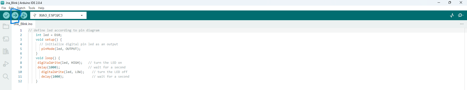
Once uploaded, you will see the connected LED blinking with a 1-second delay between each blink. This means the connection is successful and now you can explore more projects with XIAO ESP32C3!
3.4. Programm: Use my XIAO ESP32C3 as Bluetooth server
In this project, I will try to use the xiao esp32c3 as Bluetooth server. With my mobile phone, I will send a message and read a messsage. To do it, follow each step.
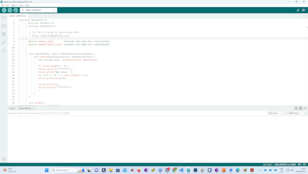
Step_01 : Connect XIAO ESP32C3 to your computer via a USB Type-C cable and the included WiFi/ Bluetooth antenna
Step_02 : Open Arduino IDE and write the code below into
| Arduino_xiao_ESP32-C3_program_1.ino | |
|---|---|
1 2 3 4 5 6 7 8 9 10 11 12 13 14 15 16 17 18 19 20 21 22 23 24 25 26 27 28 29 30 31 32 33 34 35 36 37 38 39 40 41 42 43 44 45 46 47 48 49 50 51 52 53 54 | |
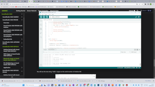
Step_03 : Upload the codes and open the Serial Monitor
Step_04 : Download and install LightBlue App on the smartphone
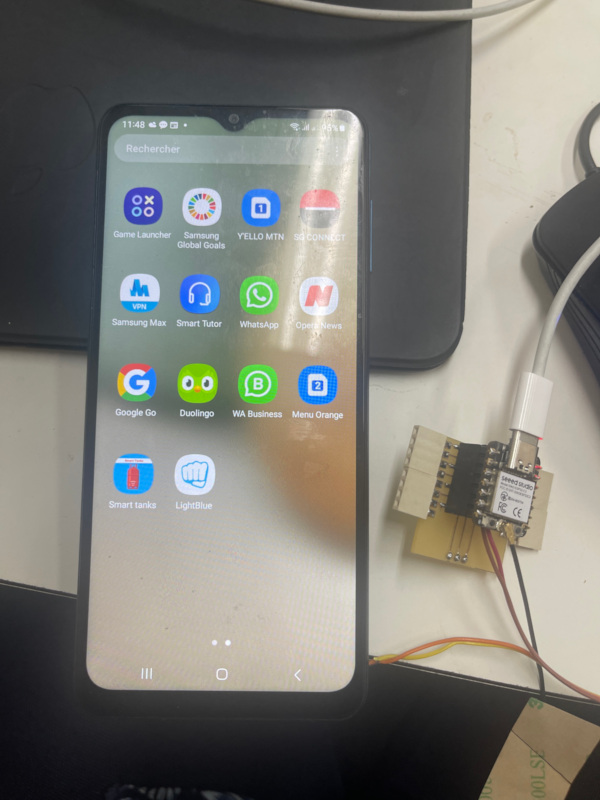
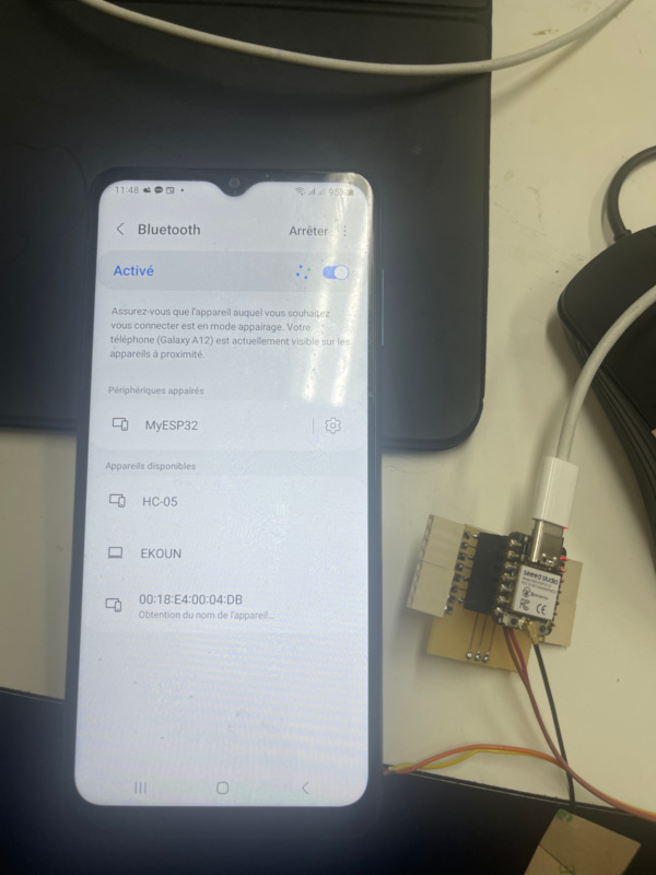
Step_05 : Open Bluetooth on the mobile phone, bring the phone close to XIAO ESP32C3, scan for devices and connect with MyESP32 device
Step_06 : Open the LightBlue app and click Bonded tab
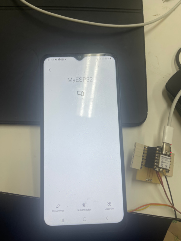
Step_07 : Click CONNECT next to MyESP32
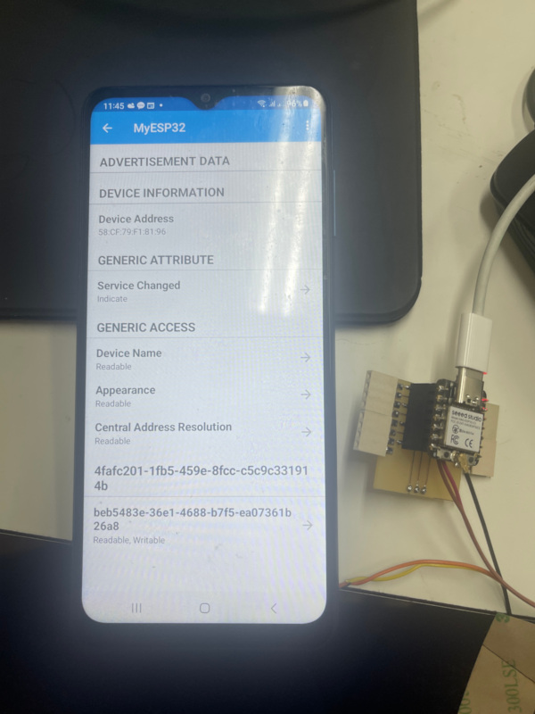
Step_08 : Click the section at the very bottom which says Readable, Writable
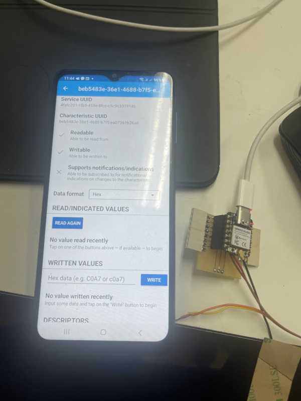
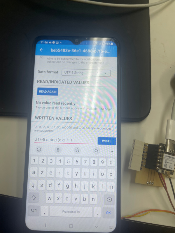
Step_09 : Under Data format drop-down menu, select UTF-8 String
Step_10 : Type “Fab Academy 2023” under WRITTEN VALUES and click WRITE You will see the text string “Hello” output on the serial monitor of Arduino IDE
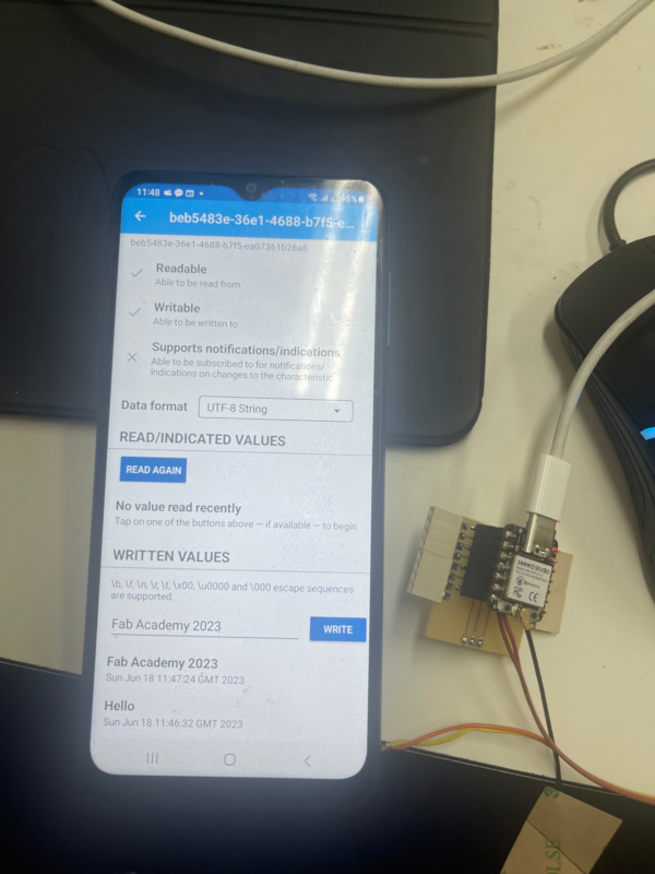
Step_11 :
4. Embedded programming with microPython language: Seeed Studio XIAO RP2040
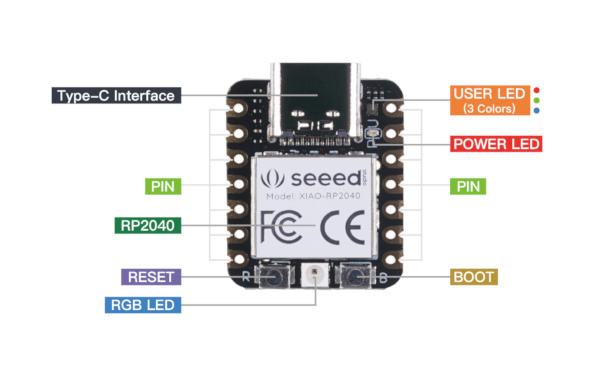
4.1. What is Seeed Studio XIAO RP2040
4.2. How to programm Seeed Studio XIAO RP2040 ?
4.2.1. Hardware setup
-
seeed studio XIO RP2040
-
Type-C cable
- PC
4.2.2. Software setup
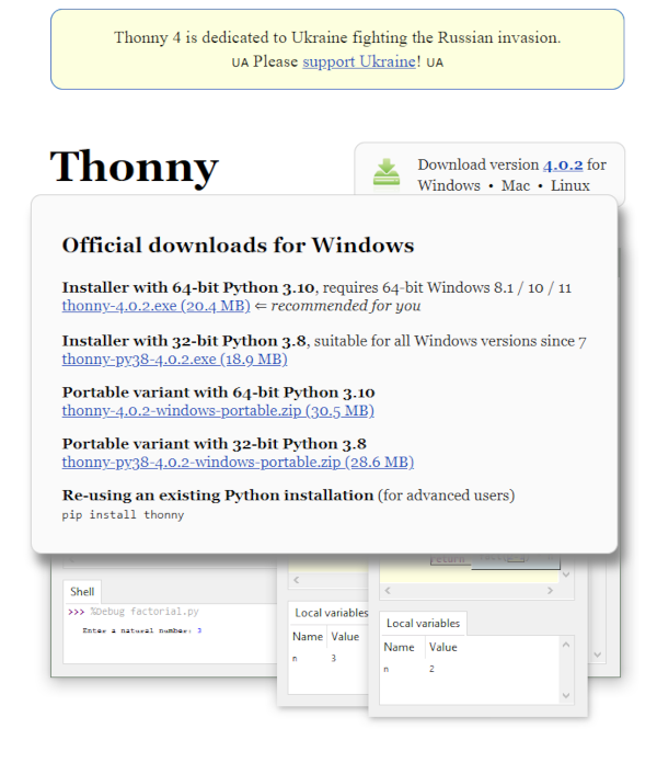
Step_01 : Download and Install the latest version of Thonny editor according to your operating system
Step_02 : Launch the Thonny and Click “Tools–>Options” to open the settings.
4.3. Programm: Blink the LED
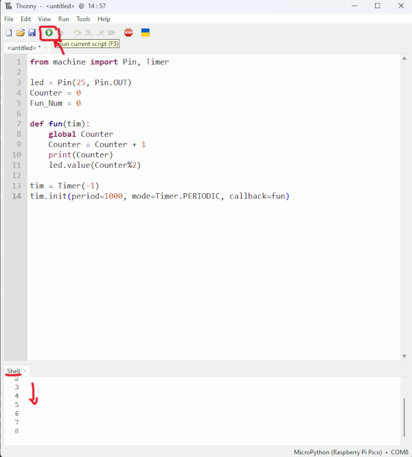
Step_01 : Upload the codes by clicking the “Run current script” button.
If it works well, you will see the LED light turn on and off once a second. And the output of the increasing number will as well be displayed in the Shell.The connection is commplete