Final Project
For a quick start to reading about my project, jump to the switching directions tab
Note: All of my files for my final project can also be found at the bottom of this page as well as when they are mentioned in the documentation
Overview
Anyone who knows me well knows that I can be indecisive and also easily stressed. Because of this I have planned out two potential final projects. The first potential project would be a record player because I love playing vinyl records and I think it would be cool to have a player that I made myself. My problem with this project is that I would have to make a phono pre-amp which takes the needle vibrations and turn them into sound that a speaker could play. I did a little online research about making your own pre-amp and have thus far not found a good source on what you need to make them or how to go about that. Me, being very easily stressed got extremely concerned and stressed about this, so in case I cannot find out how to make a pre-amp in the next few weeks I will make the other project I have planned out. This project being a triangular lamp that would respond to an IR remote to turn on and change color while the brightness of the lights would be controlled by a photoresistor or other light sensor. The light sensor would make sure that the darker it gets, the brighter the lamp will be. I want the outside panes of the lamp to have a design laser cut into them and then behind that a frosted piece of acrylic would allow the light the come out through the holes in the outside panel’s design. Below you will find sketches of each of these projects along with consideration questions.
Past students who have done similar projects and their sites: Maxine Tan, CLS Fab Lab, 2019– Record Player Jada Greene, CLS Fab Lab, 2021– Lamp
Reference Photos
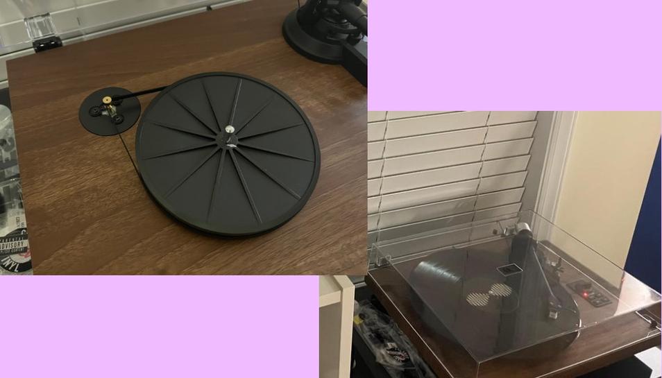
I want it to look similar to my current record player because I really like what I have currently. Images of it playing and the belt drive system can be seen below.
Sketches For Potential Projects
Consideration Questions
- What do you want your project to do?
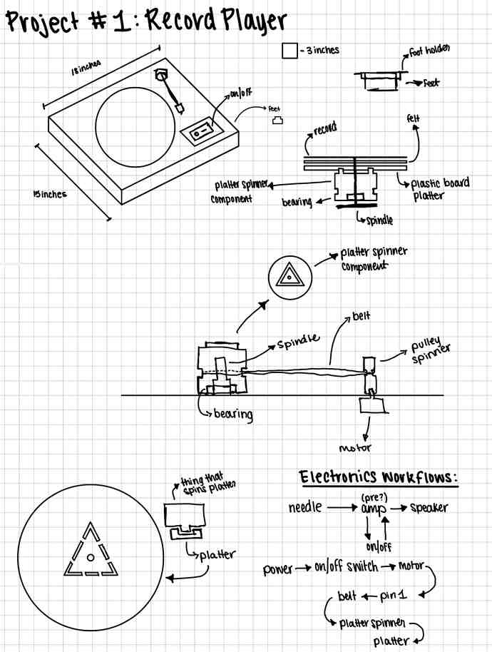
- Potential project 1: I want it to play vinyl records. The platter should spin so the needle can properly capture the sound. I would also need some type of pre-amp to take the needle vibrations and boost the signal so the music can play through the speakers.
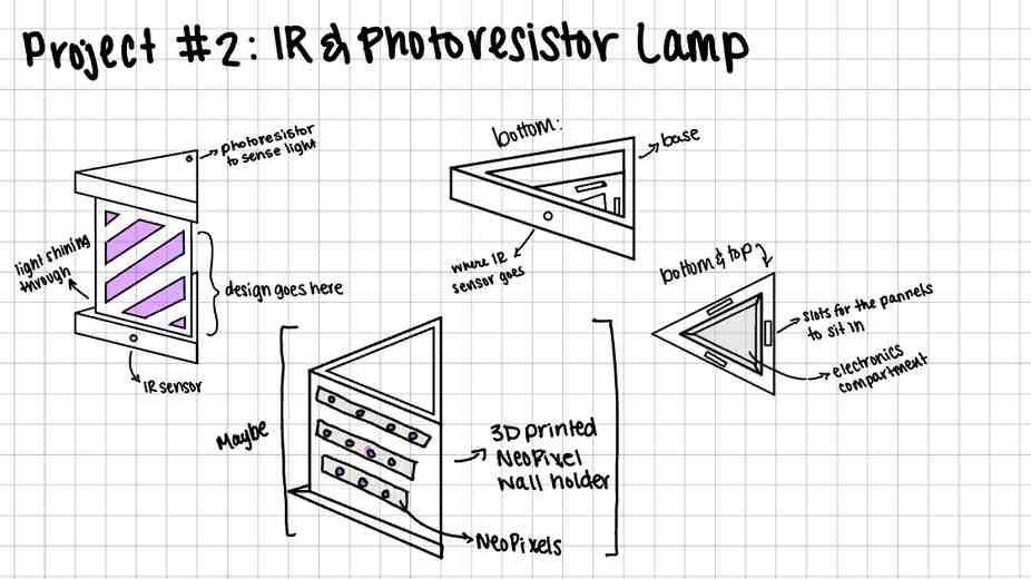
- Potential project 2: At it’s most basic I want at lamp that responds to an IR remote and the brightness of the lamp is dependent on how dark the room it. The darker the environment, the brighter I want the light to be.
- Will you project be inside or outside?
- Potential project 1: Inside, you can’t really have a record player be an outside feature
- Potential project 2: It would also be an inside project
- Will your project be portable?
- Potential project 1: No, if I pick this project I would want the base to be a big slab of wood and not be portable
- Potential project 2: No it would be a desk or side table lamp and I intend to leave it there
- Will your project connect to the internet?
- Potential project 1: No
- Potential project 2: No
- Will your project use Bluetooth?
- Potential project 1: No
- Potential project 2: I currently do not want it to connect to Bluetooth, but it could be a future possibility
- Will your project use a vinyl cutter?
- Potential project 1: No
- Potential project 2: No
- Will your project use a laser cutter?
- Potential project 1: No, but I might need to use it if something comes up as it is a highly useful tool
- Potential project 2: Yes the light side panels would be laser cut as well as the diffuser panel behind the decorative exterior panels
- Will your project use a 3D printer?
- Potential project 1: Yes I would need to design holders for the central motor and belt system I would plan on using
- Potential project 2: Possibly. I might need a 3D printer for light management on the insides or for a way to conceal my electronics
- Will your project use a large CNC machine?
- Potential project 1: Yes I would use the shopbot for the base plank which everything sits on
- Potential project 2: Yes I would use it to design the base holder for the lamp
- Will your project use intelligence (Arduino, Raspberry Pi, etc.)?
- Potential project 1: Maybe, I might need it for the on/off button and the motor on/off button, but I believe I could also do it without
- Potential project 2: Yes, I would need either an Arduino or a small RP2040 chip for this project
- What are your project inputs?
- Potential project 1: The vinyl record would be the input as well as the buttons
- Potential project 2: The IR remote and the photoresistor/other light sensor would be the inputs
- What are your project outputs?
- Potential project 1: Sound coming out of a speaker connected to the player (I would not build the speaker) would be the output
- Potential project 2: The lights responding to the input of the remote and photoresistor would be the output
- What are the dimensions of your project?
- Potential project 1: Roughly 14” x 18” but this might change
- Potential project 2: Roughly 8” x 8” x 12’ but this also might change
- What materials would you use?
- Potential project 1: I would use a plank of wood, 3D printer filament, a small motor, a piece of ~ 0.5” plastic, 1 or 2 on/off switches, possibly some thinner (1/8” or 1/4”) wood, and some skate bearings
- Potential project 2: Thin (1/8” or 1/4”) wood, some 1/8” clear acrylic, a block of wood for the base of the lamp and potentially also for the top, some NeoPixels, an Arduino or RP2040 chip, an IR sensor and remote, a photoresistor or other light sensor, and potentially some 3d printer filament
- How would you conceal you electronics?
- Potential project 1: I would hide them either inside the record player in little cavities or underneath it
- Potential project 2: I would hide them in the base of the lamp or in a small discreet housing behind the lamp
Designing Final Project in Fusion 360
The following is from week two when I made a rough mockup of what I wanted my record player final project to look like.
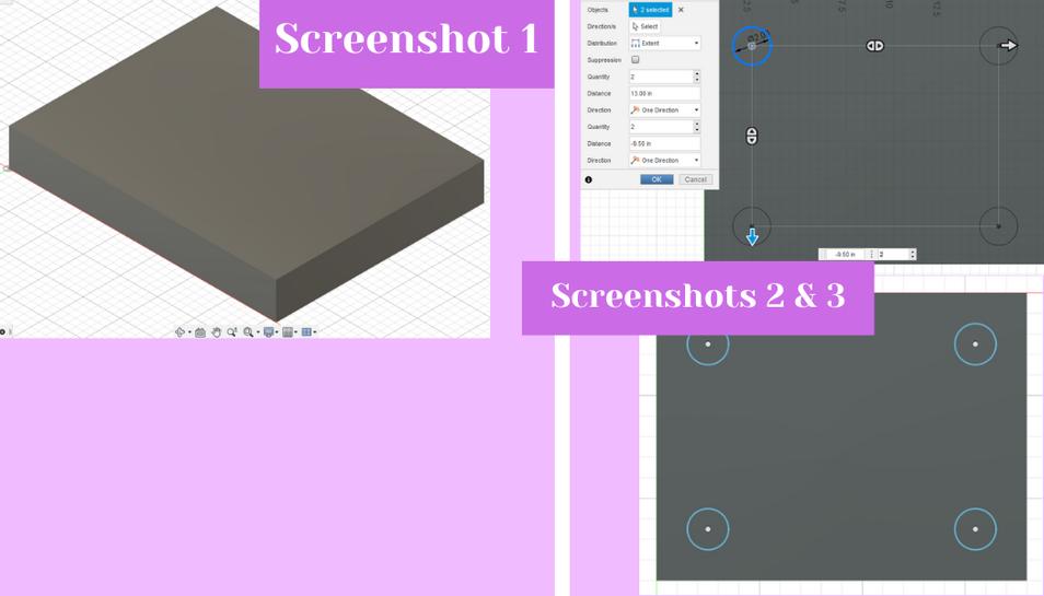
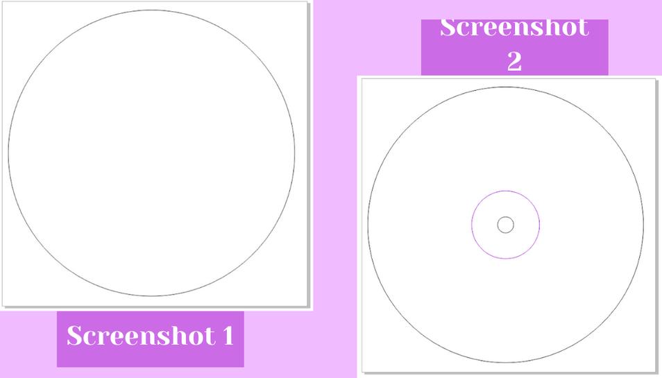
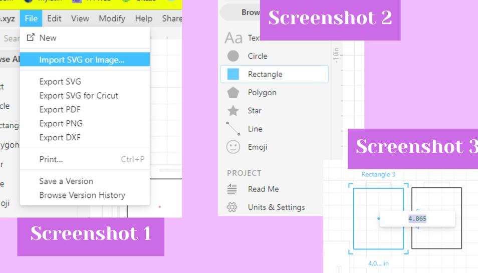
To begin I made an 14” x 18” sketch from the top bar in Fusion on the XY plane. I then clicked confirm sketch and extruded the sketch 2.5” by hitting shortcut letter “e” (screenshot 1). Next, I set about making the feet holders for the record player. I began by making one circle sketch with a diameter of 2” and then rotationally repeating that sketch twice in the X and Y direction (screenshots 2 and 3).
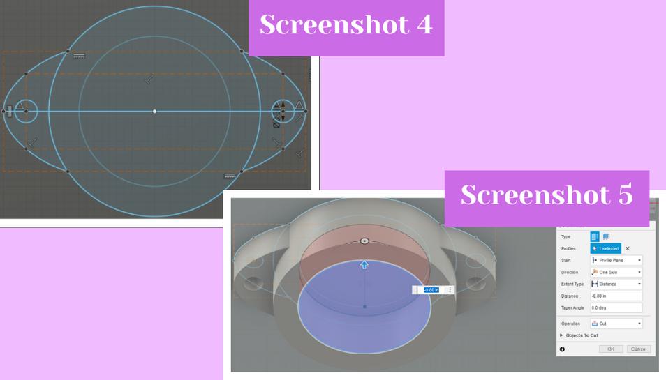
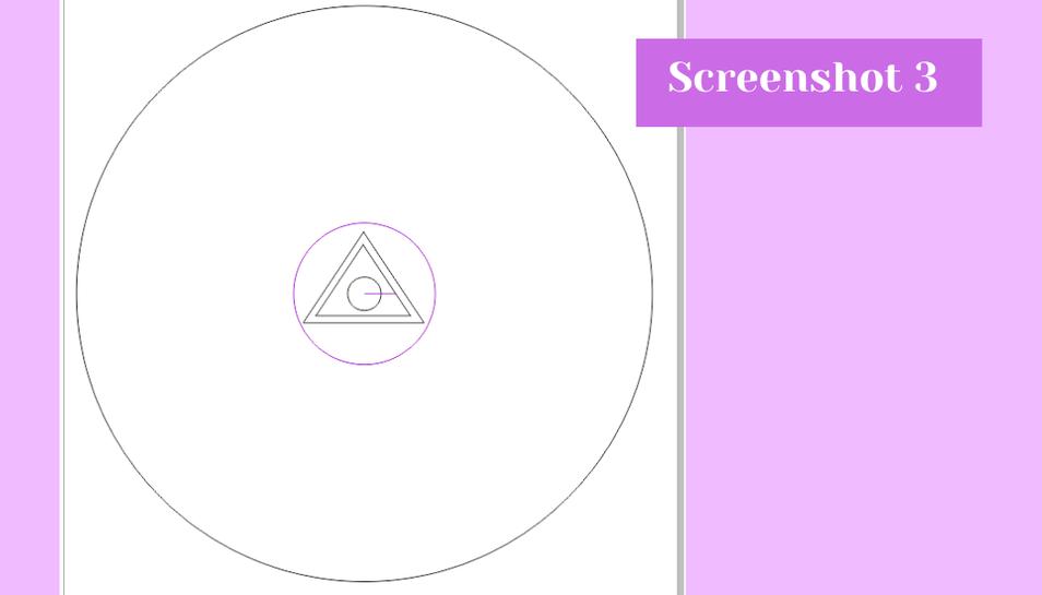
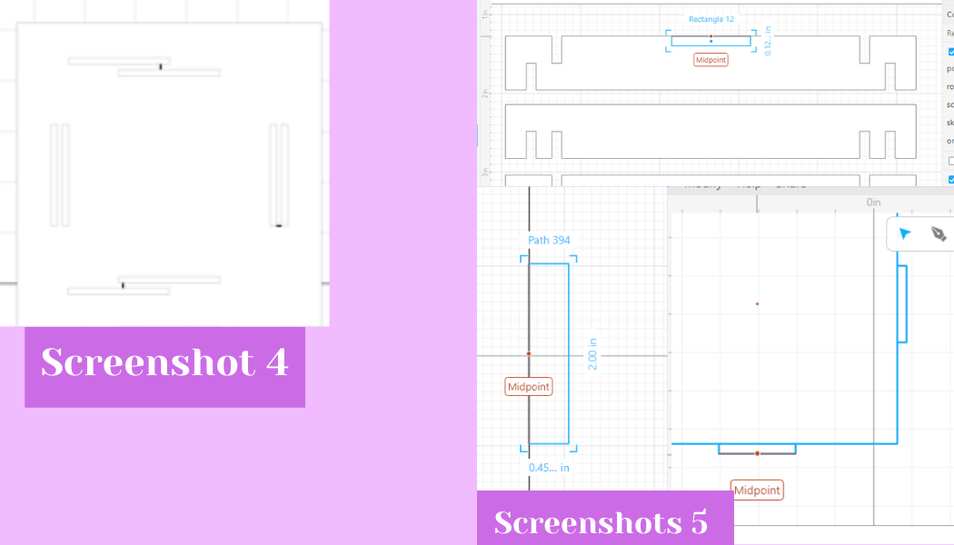
 Then I edited the sketch again and drew another larger circle, snapping it to the center of the previous circle, and also two construction line rectangular boxes for reference. With the two rectangles I used the fit point spline tool to draw an arc starting at the edge of the circle and curving to touch the outside middle of the largest rectangle while also intersecting with the corner of the smaller rectangle. Next, I added small hole designed for a screw inside the arc that I just made. (Screenshot 4) Then, I exited the sketch and went to extrude the sketch I just made by using shortcut letter “e” again. I extruded the center part more than the side brackets that would hold the piece to the base piece of wood. Then I created a new sketch from the plane of the center circle I just extruded to create another smaller circle to intrude into the piece for the material that will eventually sit inside this holder. I drew the circle using the center point circle tool, and once my sketch was finished, I intruded it -0.8” into the piece making sure that it did not go all the way through (screenshot 5).
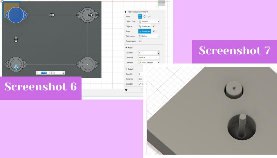
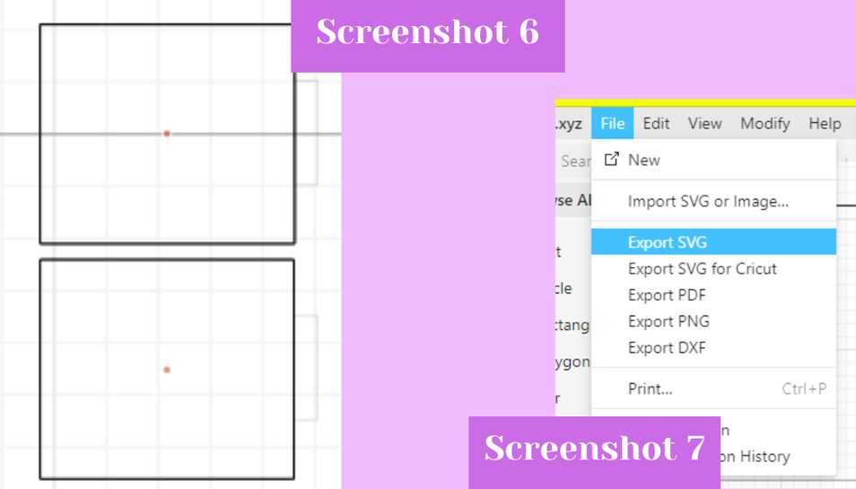
 From there I went to the Create drop down menu in the 3D modeling interface and in the drop down I went to the Pattern menu where I chose the rectangular pattern option again. I changed the object type to bodies and selected the foot holder I just made to repeat twice along both the X and Y axies (screenshot 6). With that done for now, I moved on to the top where I made two circular pocket holes on the top of the base block by making a sketch with two circles and then extruding them a negative amount into the base. These holes will serve as the base pockets to hold the motor and the shaft of the record player, as well as the piece that will hold the platter. I knew that these pockets would likely change in shape and size so I did not put much thought into their size. In the top left pocket I added a simple little mockup of my motor by adding a large cylinder with a smaller cylinder on top of it by again adding circular sketches from the faces I wanted them to sit on. In the middle pocket I added the shaft of the record player that would hold the record and platter as well as be the axis that everything would spin around. I did this by making a small flat cylinder from a sketch on the bottom of the pocket, and then by making a small but very tall cylinder from the center of the smaller circle. (Screenshot 7)
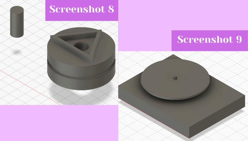
 From there I began making the two small cylindrical pieces that would attach to the motor and the shaft of the record player and allow the motor to spin the platter. I referenced my design from week one to make these pieces. I began by making three cylinders for each piece, stacked on top of each other, but I made the middle cylinder of each a smaller diameter than the other two to allow for a groove for the belt that would spin the platter. I then added a hole all the way through the larger of the cylinders because that one needs to go all the way through the shaft. I only added a small little pocket on the smaller cylinder because that one needs to attach and grip the top of the motor to spin everything. From there I worked on the triangle that would allow the platter to attach to the cylinder and allow it to spin. I knew I wanted it to be a triangle because triangles are my favourite shape and they are also the strongest shapes in nature. I began by creating a sketch on the top of the larger cylinder and by using the line tool, along with a guide line to mirror the left leg of my triangle to the right, I created an isosceles triangle on top of my cylinder. To make the smaller inside triangle I used the “ctrl” key along with the “c” key to copy the shape. Doing this activates the move/copy dialogue box in Fusion 360 where you can scale down your shape and move it around if you so desire. I scaled down the copy of the triangle and then moved it so that it would be in the center of the larger triangle by snapping it to the center of the circles of the cylinder. From there I clicked the finish sketch button and then extruded the triangle sketch up about 1/4”. (Screenshot 8) Next I created an offset plane by going to the Construct menu in Fusion and choosing the offset plane option. I made this offset plane from the top of the shaft of the record player to start the sketch of the platter. With the offset plane made, I created a sketch on the plane of two circles, one outer circle with a diameter of 12.2” and then a small inner circle which would attach to the shaft and is thus only slightly larger than the diameter of the shaft. With the sketch made, I extruded this up about 1/2” (screenshot 9).
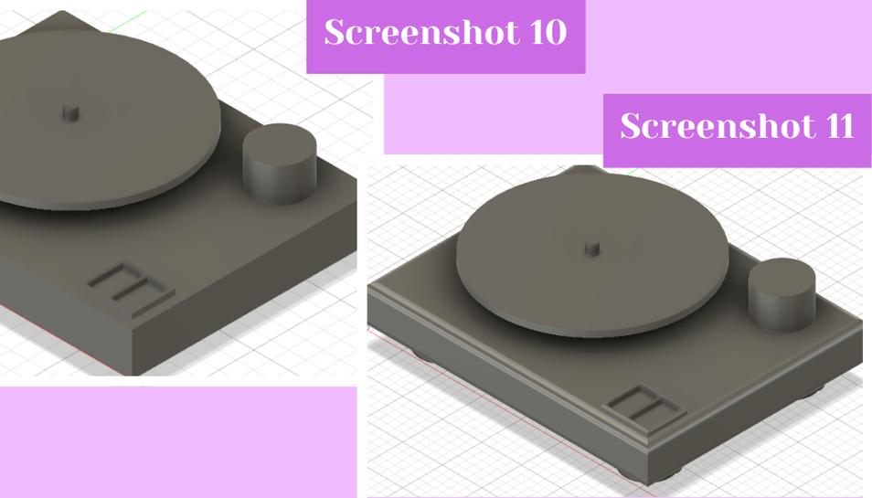
 Next I added a placeholder for the needle of the record player, as well as a placeholder for the on/off buttons for the motor and the other electronics. I did this by creating a sketch from the top of the base block of a cylinder for the needle and a rectangle with two smaller rectangles inside it for the on/off buttons. I then extruded both of the sketches up, with the button sketch being extruded about 1/4” and the needle placeholder being about 2-3” tall (screenshot 10). For final touches, I added fillets to the side of the base block, the sides of the foot holders, the side of the on/off holder, and the top of the shaft (screenshot 11).
 I also applied appearances to the models as they looked a little incomplete without (screenshot 12).
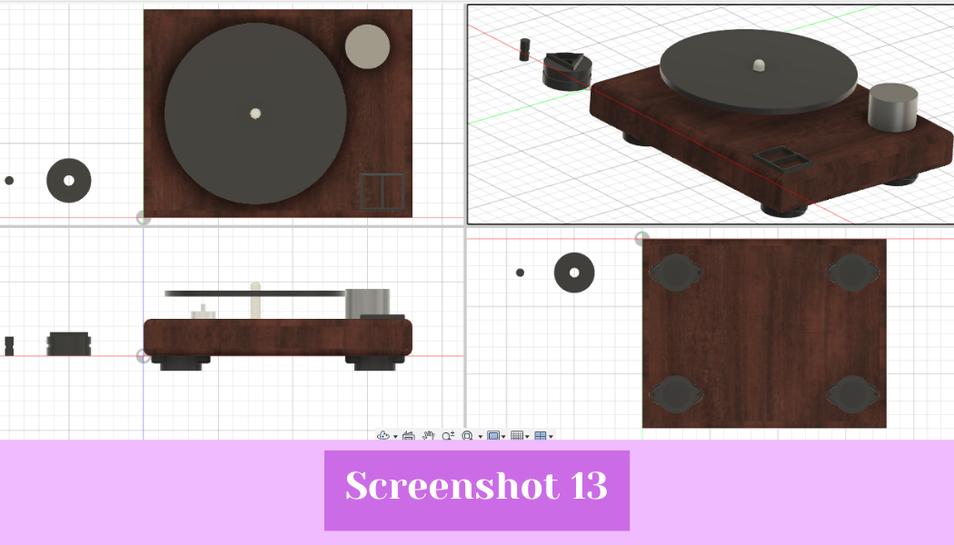
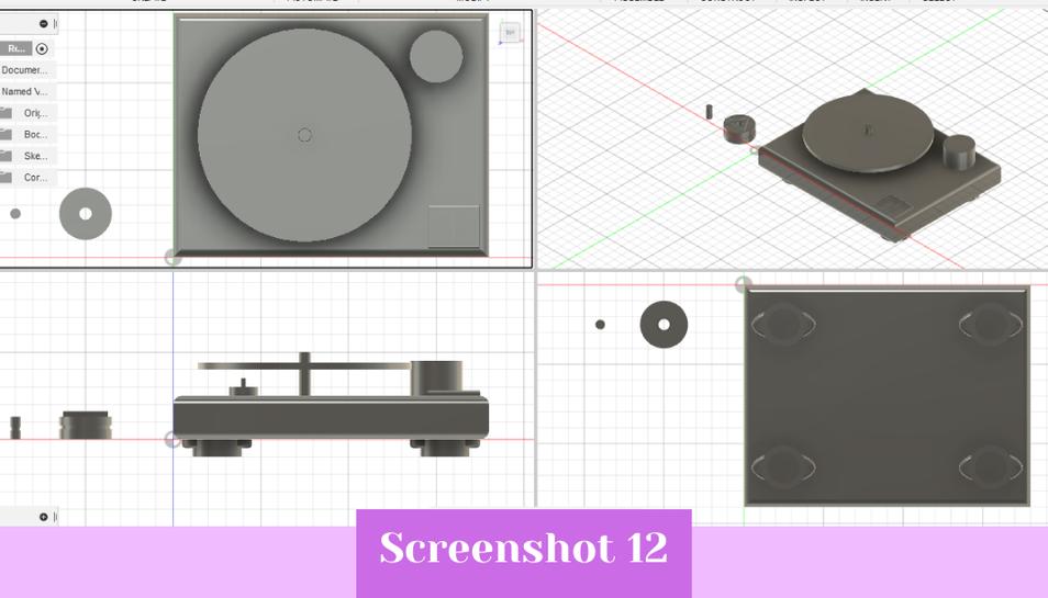 I did this by hitting shortcut letter “a” and then I dragged out a wood appearance for the base block, and black or white plastic appearance for everything else (screenshot 13). With that I completed my model, and saved it as a .svg which you can download using the link below.
Designing in CorelDraw
I decided to make a first version of my platter for my record player in Corel. I think I will end up milling the platter so this design could probably be used for both that and to laser cut a test version of it before I commit to using the ShopBot and making the final version. I began by creating a new document and changing the document page size and the document units. I changed it to 13 inches for the width and height as this was slightly larger than the design I want to make. I then used the circle tool from the left hand shapes menu to draw out a random picture. To make the circle my desired measurements I went up to the top bar in CorelDraw and changed the size of the circle in the left hand length and width boxes rather than trying to drag out the circle to how big I wanted it. I changed the dimensions 12.2” inches because a standard 33.3 RPM record is 12” inches but sometimes 10” inches (screenshot 1). Then I added a second circle and changed its dimensions to .026” inches for both the length and width. This circle will be for the center rod that will hold the platter and record and allow them to spin. I measured the diameter of the center rod of my record player at home using calipers and it came out to 7 mm (screenshot 2) so I made that the diameter of the center hole. Next, I added in a purple guideline for adding my triangle.
 I added the 3” inch circle that the triangle holder would be attached to per my Fusion 360 design. The circle I snapped to the middle of the other two circles. Next, I added a polygon from the left side bar. The polygon automatically sets to have 4 side, which is not ideal for making a triangle so I changed the number of side in the top bar from 4 to 3. Next, I referred to my Fusion 360 design for the triangle and used the measure tool in Fusion 360 to make the triangle in CorelDraw. I found the length of the base of the triangle, and then I also found the altitude of the triangle. I took these two measurements and put them in for the width and length of the triangle to get a triangle that was congruent to the triangle in Fusion 360. I did this for both the smaller and larger triangles. Next, I double checked this by drawing a purple guideline from the center of all of the circles I made to the edge of both triangles making sure that in both Corel and Fusion they were the same distance apart, further confirming that they are congruent and placed correctly. To finish off my design I made all black lines hairline so that if cut on the laser cutter, they would vector rather than raster. (Screenshot 3) You can download the file using the link below.
Switching Final Project Directions: Idea Two
Consideration Questions
What will it do?
My lamp will react to both ambient light in an environment and to an IR remote. Based on those two factors the lamp should change color and brightness, with the lamp brightness changing based on the photoresistor, and the lamp color changing based on the remote.
Who’s done what beforehand?
Jada Greene made a similar lamp last year but used different inputs on her lamp (temperature and sound) and I think her project is a good reference point for my lamp because she, like I will have to do, combined codes for two inputs. I also like the aesthetics of her lamp which I will replicate for my lamp, but in a slightly different way.
What will you design?
I will design the outside casing holder, the electronics connection boards, the NeoPixel holder, and the code that controls the inputs and NeoPixels. Essentially I will make all of my project.
What materials and components will be used?
I plan to use some 1/8” wood, a block of thicker wood for the top and bottom caps, 3D printer filament, NeoPixels, some copper FR1 board for any custom boards, an IR remote and sensor, and a photoresistor.
Where will the materials come from?
All of these materials I can find in our lab so I should not have to purchase anything unless our lab is out of it.
How much will they cost?
Because all materials can be found in the lab, the materials will not cost anything extra to source, but if someone else were to make this the following BOM would be an estimate of cost for this project
| Item | Price | Quantity | Link |
|---|---|---|---|
| 1m NeoPixels | $14.95 | 1 strip | Link |
| FR1 Board | $1.00 (per board) | ~ 1 board | Link |
| 1/8” plywood | $18.00 | 1 | Link |
| 1/8” clear acrylic | $43.88 | less than 1 sheet | Link |
| A photoresistor | $0.95 | 1 | Link |
| An IR sensor | $0.95 | 1 | Link |
| An IR remote | $4.95 | 1 | Link |
| Seeed Xiao RP2040 board | $5.40 | 1 | Link |
| Surface mount header pins | $4.74 | 2 packs of 8 | Link |
| Jumper wires | $6.96 | 1 pack | Link |
| Vinyl sticker sheets | $11.99 | 1 pack | Link |
| 3D Printer fillament PLA | $29.99 | 1 roll but will use far less than a roll | Link |
| Frosting spray paint | $6.91 | 1 can | Link |
What parts and systems will be made?
I will make the system that will detect the ambient light and also one that detects the IR remote. I will make the outer cast for the lamp from wood and acrylic, and I will also make the NeoPixels holder for inside the lamp. My proposed parts list is as followed: - 1 to 2 pieces of thick wood - 1/8” plywood - 1/8” acrylic - Frosting spray paint - FR1 copper board - A microcontroller (seed xiao rp2040, an ATTiny, or maybe an Arduino??) - NeoPixel strip - A photoresistor - An IR remote and sensor - 3D printer filament for a NeoPixel holder
What processes will be used?
I will use laser cutting, CNC milling, CAD designing, 3D printing, soldering, electronics design and production, and programming.
What questions need to be answered?
I need to figure out how to combine codes for both an IR remote and a photoresistor and figure out how to best combine the two inputs with color and brightness of the NeoPixels. I also need to figure out whether I make one big electronics board or 2-4 smaller separate ones. I also need to work out why the IR remotes are inconsistent and if there is a way to get around that
How will it be evaluated?
My lamp should be evaluated on a functionality basis. The lamp should work as described to change colors and brightness based on the ambient light and an IR remote. It should also be evaluated on neatness and appearance as it is an aesthetic object.
License
Creative Commons Attribution-NonCommercial 4.0 International License
You can see more about the license and why I chose it on my week 17 documentation page
Electronics
Getting Started- IR Remote
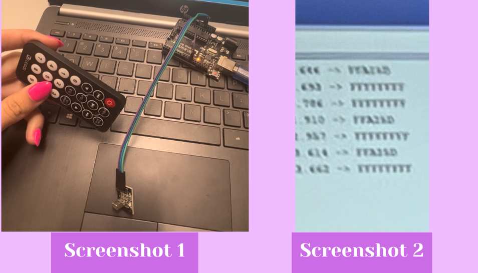
I began my electronics by trying to receive values from an IR remote and receiver. I did this by connecting an IR receiver to an Arduino Uno and connecting the 5v –> R (power pin), GND –> G (ground pin), and 11 –> Y (data pin) (screenshot 1). I then uploaded the following code I got from the Elegoo Arduino starter library which is supposed to receive the values of the IR remote buttons and print them into the serial monitor as the button you pressed. It also includes a map of which button corresponds to which HEX code for the button at the bottom of the code.
First Code IR
//www.elegoo.com
//2020.3.12
// Used by Ginny Foster for Final Project during Fab Academy 2023

#include "IRremote.h"
#include "IR.h"

IRrecv irrecv(RECEIVER);     // create instance of 'irrecv'
decode_results results;      // create instance of 'decode_results'

void setup() {
  Serial.begin(9600);
  Serial.println("IR Receiver Button Decode");
  irrecv.enableIRIn();
}

void loop()
{
  int tmpValue;
  if (irrecv.decode(&results)) // have we received an IR signal?
  {
    for (int i = 0; i < 23; i++)
    {
      if ((keyValue[i] == results.value) && (i<KEY_NUM))
      {
        Serial.println(keyBuf[i]);
        tmpValue = results.value;
      }
      else if(REPEAT==i)
      {
        results.value = tmpValue;
      }
    }
    irrecv.resume(); // receive the next value
  }
//The implementation effect of the above program is
//the same as that of the following, but it is more concise

//    switch(results.value)
//  {
//  case 0xFFA25D: Serial.println("POWER"); break;
//  case 0xFFE21D: Serial.println("FUNC/STOP"); break;
//  case 0xFF629D: Serial.println("VOL+"); break;
//  case 0xFF22DD: Serial.println("FAST BACK");    break;
//  case 0xFF02FD: Serial.println("PAUSE");    break;
//  case 0xFFC23D: Serial.println("FAST FORWARD");   break;
//  case 0xFFE01F: Serial.println("DOWN");    break;
//  case 0xFFA857: Serial.println("VOL-");    break;
//  case 0xFF906F: Serial.println("UP");    break;
//  case 0xFF9867: Serial.println("EQ");    break;
//  case 0xFFB04F: Serial.println("ST/REPT");    break;
//  case 0xFF6897: Serial.println("0");    break;
//  case 0xFF30CF: Serial.println("1");    break;
//  case 0xFF18E7: Serial.println("2");    break;
//  case 0xFF7A85: Serial.println("3");    break;
//  case 0xFF10EF: Serial.println("4");    break;
//  case 0xFF38C7: Serial.println("5");    break;
//  case 0xFF5AA5: Serial.println("6");    break;
//  case 0xFF42BD: Serial.println("7");    break;
//  case 0xFF4AB5: Serial.println("8");    break;
//  case 0xFF52AD: Serial.println("9");    break;
//  case 0xFFFFFFFF: Serial.println(" REPEAT");break;
//  default:
//    Serial.println(" other button   ");

 // }// End Case
}
This code did work and printed the button values into the serial monitor so I decided to incorperate NeoPixels next (screenshot 2).
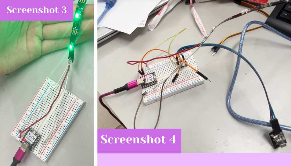
 I found code from this website which would take a button press from an IR remote and would turn on NeoPixels if the button was pressed. I decided to see if I could get this code to work, but first I wanted to duble check that my NeoPixel test strip was working. I did this by connecting the strip to pin D4 of a SEEED Xiao RP2040 and the power and ground to the 5V and GND of the SEEED Xiao RP2040. Next, I uploaded the simple code from the Adafruit NeoPixel library. The strip began flashing green so I knew the strip was good and I could proceed with the IR-remote-NeoPixel code (screenshot 3). I started by connecting the IR reciver: 5v –> R (power pin), GND –> G (ground pin), and D0 –> Y. Then I connected the NeoPixel strip: 5v –> 5v, GND –> GND, and Din (data pin) –> D4 (screenshot 4).
 From there I uploaded the following code which had the pins replaced to match the SEEED Xiao RP2040 and I also replaced the HEX codes that this code originally had to match the ones from the code above for buttons 1, 2, and 3.
First Attempt at NeoPixel-IR-remote code
// From this website: https://learn.adafruit.com/using-an-infrared-library/about-ir-libraries and from simple example code from Adafruit NeoPixel library
// Used by Ginny Foster for Final Project during Fab Academy 2023

#include <Adafruit_NeoPixel.h>
#include <IRLibAll.h>

IRrecv myReceiver(2);//receiver on pin D0
IRdecode myDecoder;//Decoder object

//One NeoPixel connected to pin D4
Adafruit_NeoPixel strip = Adafruit_NeoPixel(1,D4,NEO_GRB + NEO_KHZ800);

void setup() {
  strip.begin();
  strip.show(); // Initialize all pixels to 'off'
  myReceiver.enableIRIn(); // Start the receiver
}

void loop() {
  if (myReceiver.getResults()) {
    myDecoder.decode();
    if (myDecoder.protocolNum == NEC) {
      switch(myDecoder.value) {
        case 0xFF30CF:  // 1
          strip.setPixelColor(0,255,0,0);//Red
          break;
        case 0xFF18E7:  // 2
          strip.setPixelColor(0,0,255,0);//Green
          break;
        case 0xFF7A85:  // 3
          strip.setPixelColor(0,0,0,255);//Blue
          break;
      }
    strip.show();
    myReceiver.enableIRIn(); //Restart the receiver
    }
  }
}
The code uploaded and the first pixel would change color based on the button presses of 1, 2, and 3, but if I tried to change the color of the NeoPixels after a few minutes of uploading, the pixels would not change color.
I was a little lost on why so I just decided to combine two codes from the website. One of them was the code that received the button values and printed them into the serial monitor, and once which displayed color on the NeoPixels if a particular button was pressed. The NeoPixel part of the code is actually the code I used above, but because I was unsure if the remote was working correctly I wanted part of the code to print in the monitor what was being received from the remote.
// From this website: https://learn.adafruit.com/using-an-infrared-library/about-ir-libraries
// Adapted by Ginny Foster for Final Project during Fab Academy 2023

#include <Adafruit_NeoPixel.h>
#include <IRLibAll.h>

IRrecv myReceiver(2);//receiver on pin D0
IRdecode myDecoder;//Decoder object

//One NeoPixel connected to pin D4
Adafruit_NeoPixel strip = Adafruit_NeoPixel(3,D4,NEO_GRB + NEO_KHZ800);

void setup() {
  strip.begin();
  strip.show(); // Initialize all pixels to 'off'
  myReceiver.enableIRIn(); // Start the receiver
   Serial.begin(9600);
  delay(2000); while (!Serial); //delay for Leonardo
  Serial.println(F("Ready to receive IR signals"));
}

void loop() {
  if (myReceiver.getResults()) {
    myDecoder.decode();
    if (myDecoder.protocolNum == NEC) {
      switch(myDecoder.value) {
        case 0xff30cf:
          strip.setPixelColor(0,255,0,0);
          break;
        case 0xff18e7:
          strip.setPixelColor(0,255,165,0);
          break;
        case 0xff7a85:
          strip.setPixelColor(0,255,245,0);
          break;
      }
    strip.show();
    myReceiver.enableIRIn(); //Restart the receiver
    }
  }
}
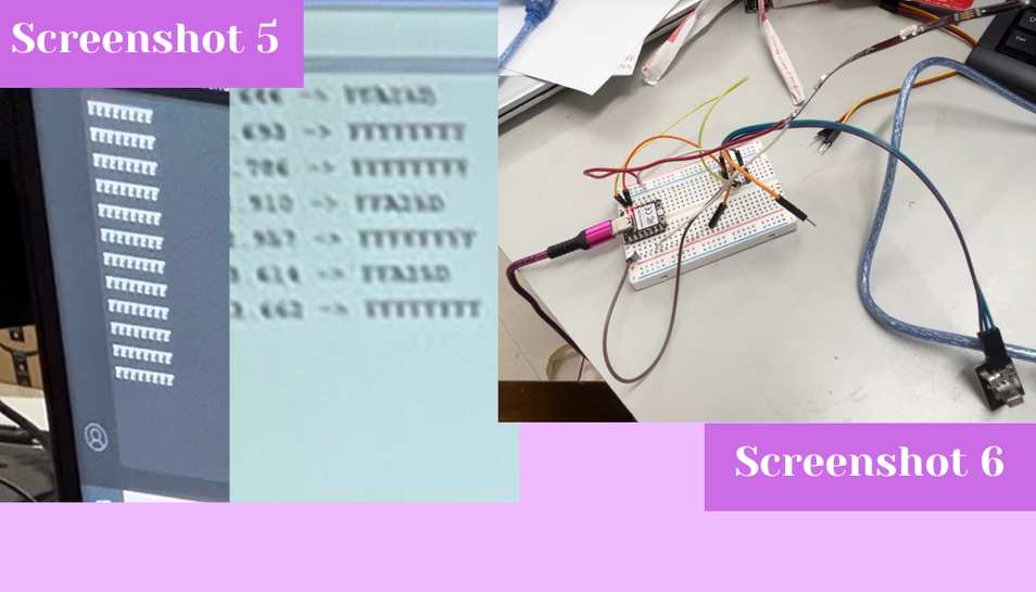
This code also worked but then would stop changing the NeoPixel’s color after a few minutes after uploading too, and in the serial monitor I noticed that the values the receiver was reciving were either complete gibberish, were FFFFFF, or occasionally were the correct HEX codes for a button (screenshot 5). This was confusing and I ended up submitting a question to former Fab graduate and electrical engineering professor Dr. Adam Harris because that day he was taking questions from the CLS Fab Lab students. I asked him if he knew why I was receiving random values, FFFFFF, or sometimes actual HEX values, and if he knew why the NeoPixels wouldn’t change color a few minutes after upload. While I was waiting for other students who where asking Dr. Harris questions, I began looking for other codes that inegrated IR remotes with NeoPixels. While looking for possabilites, I came across this website which instead of using the hex values of the remote, the code maps each to a number and prints it in the serial monitor and uses the value of that number to indicate a button push. This also eliminates the repetitive hex code FFFFFF being printed in the serial monitor when a button is repetitively pressed or held down. I first tried the the code that only prints in the serial monitor the number that is mapped to the HEX code for the button to see if the code worked. I kept the same wiring on the breadboard (screenshot 6).
// From this website: https://roboticsbackend.com/arduino-ir-remote-controller-tutorial-setup-and-map-buttons/
// Used by Ginny Foster for Final Project during Fab Academy 2023
#include <IRremote.h>

#define IR_RECEIVE_PIN D0

void setup() {
  Serial.begin(9600);
  IrReceiver.begin(IR_RECEIVE_PIN);
}

void loop() {
  if (IrReceiver.decode()) {
    IrReceiver.resume();
    Serial.println(IrReceiver.decodedIRData.command);
  }
}
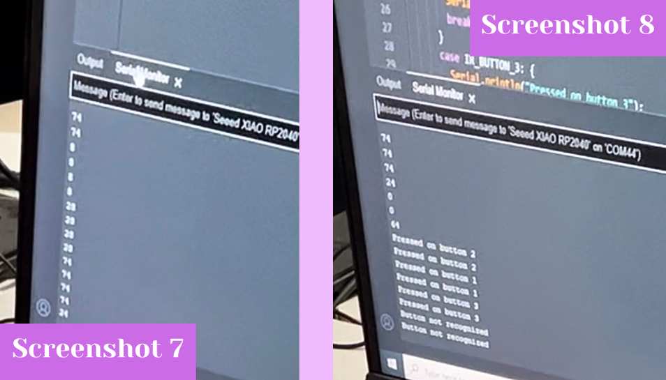
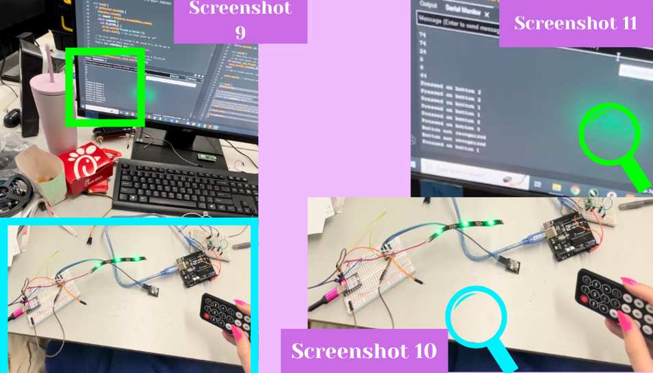
This code worked first try and gave me consistant numbers for each button I pressed (screenshot 7). Next, I began pressing every button on my remote and writing down what number came up in the serial monitor.
After I had a list of each number for every button I decided to try the longer version of the code above which prints in the serial monitor pressed on button __ depending on what button is pressed. I initially tried it with just the preset buttons, but I later expanded it as you can see below.
Working IR Remote Original Code
// From this website: https://roboticsbackend.com/arduino-ir-remote-controller-tutorial-setup-and-map-buttons/
// Used by Ginny Foster for Final Project during Fab Academy 2023

#include <IRremote.h>

#define IR_RECEIVE_PIN D0

#define IR_BUTTON_1 12
#define IR_BUTTON_2 24
#define IR_BUTTON_3 94
#define IR_BUTTON_PLAY_PAUSE 64

void setup() {
  Serial.begin(9600);
  IrReceiver.begin(IR_RECEIVE_PIN);
}

void loop() {
  if (IrReceiver.decode()) {
    IrReceiver.resume();
    int command = IrReceiver.decodedIRData.command;
    switch (command) {
      case IR_BUTTON_1: {
        Serial.println("Pressed on button 1");
        break;
      }
      case IR_BUTTON_2: {
        Serial.println("Pressed on button 2");
        break;
      }
      case IR_BUTTON_3: {
        Serial.println("Pressed on button 3");
        break;
      }
      case IR_BUTTON_PLAY_PAUSE: {
        Serial.println("Pressed on button play/pause");
        break;
      }
      default: {
        Serial.println("Button not recognized");
      }
    }
  }
}
After I got this working (screenshot 8)
 I then took the numbers I wrote down for buttons 1-9 and STRE, EQ, and play-pause and then began writing more
 #define’s at the top of my code and adding in case’s in my main code to print “Pressed on button _” in the serial monitor if the button was pressed. This resulted in the expanded code below and also worked like the shortened one above when I tested it (screenshot 8 and 11).
Working IR Remote Expanded Code
// From this website: https://roboticsbackend.com/arduino-ir-remote-controller-tutorial-setup-and-map-buttons/
// Adapted by Ginny Foster for Final Project during Fab Academy 2023

#include <IRremote.h>

#define IR_RECEIVE_PIN D0

#define IR_BUTTON_1 12
#define IR_BUTTON_2 24
#define IR_BUTTON_3 94
#define IR_BUTTON_4 8
#define IR_BUTTON_5 28
#define IR_BUTTON_6 90
#define IR_BUTTON_7 66
#define IR_BUTTON_8 82
#define IR_BUTTON_9 74
#define IR_BUTTON_0 22
#define IR_BUTTON_EQ 25
#define IR_BUTTON_STRE 13
#define IR_BUTTON_PLAY_PAUSE 64

#define DATA_PIN D4 // Data pin for the NeoPixel strip

void setup() {
  Serial.begin(9600);
  IrReceiver.enableIRIn();
}

void loop() {
  if (IrReceiver.decode()) {
    int command = IrReceiver.decodedIRData.command;
    switch (command) {
      case IR_BUTTON_1:
        Serial.println("Pressed on button 1");
        break;
      case IR_BUTTON_2:
        Serial.println("Pressed on button 2");
        break;
      case IR_BUTTON_3:
        Serial.println("Pressed on button 3");
        break;
      case IR_BUTTON_4:
        Serial.println("Pressed on button 4");
        break;
      case IR_BUTTON_5:
        Serial.println("Pressed on button 5");
        break;
      case IR_BUTTON_6:
        Serial.println("Pressed on button 6");
        break;
      case IR_BUTTON_7:
        Serial.println("Pressed on button 7");
        break;
      case IR_BUTTON_8:
        Serial.println("Pressed on button 8");
        break;
      case IR_BUTTON_9:
        Serial.println("Pressed on button 9");
        break;
      case IR_BUTTON_0:
        Serial.println("Pressed on button 0");
        break;
      case IR_BUTTON_EQ:
        Serial.println("Pressed on button EQ");
        break;
      case IR_BUTTON_STRE:
        Serial.println("Pressed on button STRE");
        break;
      case IR_BUTTON_PLAY_PAUSE:
        Serial.println("Pressed on button Play Pause");
        break;
      default:
        Serial.println("Button not recognized");
        break;
    }
    IrReceiver.resume();
  }
}
From there, because I knew that the remote was working consistently, I decided to add in commands to turn on NeoPixels into the code for each button. The command I took to turn them on is put inside the case for each button and the code is taken from the simple example in the NeoPixel Adafruit library, but instead of green I replaced each RGB value with the color I wanted it to be. When I tested this code, surprisingly it worked, and I noticed that if I tried to change the color ~10 minutes after I uploaded the code, that the NeoPixels would still change color (screenshot 10, see above). This resolves my issue of consistency with the color changing.
Working IR Remote Code with NeoPixels
// From this website: https://roboticsbackend.com/arduino-ir-remote-controller-tutorial-setup-and-map-buttons/ and from the Adafruit NeoPixel library code "simple"
// Adapted by Ginny Foster for Final Project during Fab Academy 2023

#include <IRremote.h>
#include <Adafruit_NeoPixel.h>

#define IR_RECEIVE_PIN D0

#define IR_BUTTON_1 12
#define IR_BUTTON_2 24
#define IR_BUTTON_3 94
#define IR_BUTTON_4 8
#define IR_BUTTON_5 28
#define IR_BUTTON_6 90
#define IR_BUTTON_7 66
#define IR_BUTTON_8 82
#define IR_BUTTON_9 74
#define IR_BUTTON_0 22
#define IR_BUTTON_EQ 25
#define IR_BUTTON_STRE 13
#define IR_BUTTON_PLAY_PAUSE 64

#define NUMPIXELS 50 // Number of NeoPixels in the strip
#define DATA_PIN D4 // Data pin for the NeoPixel strip

Adafruit_NeoPixel pixels(NUMPIXELS, DATA_PIN, NEO_GRB + NEO_KHZ800);

#define DELAYVAL 100 // Time (in milliseconds) to pause between pixels

void setup() {
  Serial.begin(9600);
  IrReceiver.enableIRIn();
  pixels.begin();
}

void loop() {
  if (IrReceiver.decode()) {
    int command = IrReceiver.decodedIRData.command;
    switch (command) {
      case IR_BUTTON_1:
        Serial.println("Pressed on button 1");
        pixels.clear();
        for(int i=0; i<NUMPIXELS; i++) { // For each pixel...
        pixels.setPixelColor(i, pixels.Color(245, 0, 87)); // pink
        pixels.show();
        break;
        }
      case IR_BUTTON_2:
        Serial.println("Pressed on button 2");
        pixels.clear();
        for(int i=0; i<NUMPIXELS; i++) { // For each pixel...
        pixels.setPixelColor(i, pixels.Color(255, 0, 0)); // red
        pixels.show();
        break;
        }
      case IR_BUTTON_3:
        Serial.println("Pressed on button 3");
        pixels.clear();
        for(int i=0; i<NUMPIXELS; i++) { // For each pixel...
        pixels.setPixelColor(i, pixels.Color(255, 61, 0)); // orange
        pixels.show();
        break;
        }
      case IR_BUTTON_4:
        Serial.println("Pressed on button 4");
        pixels.clear();
        for(int i=0; i<NUMPIXELS; i++) { // For each pixel...
        pixels.setPixelColor(i, pixels.Color(255, 234, 0)); // yellow
        pixels.show();
        break;
        }
      case IR_BUTTON_5:
        Serial.println("Pressed on button 5");
        pixels.clear();
        for(int i=0; i<NUMPIXELS; i++) { // For each pixel...
        pixels.setPixelColor(i, pixels.Color(139, 195, 74)); // green
        pixels.show();
        break;
        }
      case IR_BUTTON_6:
        Serial.println("Pressed on button 6");
        for(int i=0; i<NUMPIXELS; i++) { // For each pixel...
        pixels.setPixelColor(i, pixels.Color(0, 172, 193)); // light blue
        pixels.show();
        break;
        }
      case IR_BUTTON_7:
        Serial.println("Pressed on button 7");
        for(int i=0; i<NUMPIXELS; i++) { // For each pixel...
        pixels.setPixelColor(i, pixels.Color(41, 121, 255)); // blue
        pixels.show();
        break;
        }
      case IR_BUTTON_8:
        Serial.println("Pressed on button 8");
        for(int i=0; i<NUMPIXELS; i++) { // For each pixel...
        pixels.setPixelColor(i, pixels.Color(206, 47, 216)); // purple
        pixels.show();
        break;
        }
      case IR_BUTTON_9:
        Serial.println("Pressed on button 9");
        for(int i=0; i<NUMPIXELS; i++) { // For each pixel...
        pixels.setPixelColor(i, pixels.Color(106, 27, 154)); // light purple
        pixels.show();
        break;
        }
      default:
        Serial.println("Button not recognized");
        break;
    }
    IrReceiver.resume();
  }
}
Expanding onwards with a photoresistor
After I knew the remote was working with NeoPixels consistantly I moved to add the brightness aspect of my project. I started by making sure I could just control the brightness of a strip of NeoPixels without a remote involved. I added a photoresistor to my breadboard and connected the 5v –> 5v, GND –> GND, and the data pin –> A1 of the SEEED Xiao RP2040. I then referenced the brightness commands from the RGBWstrandtest example code from the Adafruit NeoPixel library and adapted it using what I knew about photoresistors to first read the value of the photoresistor by doing: int photoValue = analogRead(PHOTO_PIN);. Then I mapped the value that it read to 0-255 int brightness = map(photoValue, 0, 1023, 0, 255); because that is the number that the NeoPixels top out at, but the photoresistor will give values more than 255, thus the need to scale them by mapping. From there I used pixels.setBrightness(brightness); to set the brightness of the NeoPixels. All of this combined will read the value of the photoresistor and set the NeoPixel brightness based on the ambient light in whatever environment you’re in.
Working NeoPixel-photoresistor code
// Code partially from the Adafruit NeoPixel library code "simple"
// Adapted by Ginny Foster for Final Project during Fab Academy 2023

#include <Adafruit_NeoPixel.h>
#define PHOTO_PIN A1 // Data pin for the photoresistor
#define NUMPIXELS 50 // Number of NeoPixels in the strip
#define DATA_PIN D4 // Data pin for the NeoPixel strip
Adafruit_NeoPixel pixels(NUMPIXELS, DATA_PIN, NEO_GRB + NEO_KHZ800);
#define DELAYVAL 100 // Time (in milliseconds) to pause between pixels

void setup() {
  Serial.begin(9600);
  IrReceiver.enableIRIn();
  pixels.begin();
}

void loop() {
int photoValue = analogRead(PHOTO_PIN);  // Read value from photoresistor
int brightness = map(photoValue, 0, 1023, 0, 255);  // Map photoValue to brightness range (0-255)
Serial.println(photoValue);
pixels.setBrightness(brightness);  // Set NeoPixel strip brightness
pixels.setPixelColor(i, pixels.Color(255, 0, 0));
pixels.show();
}
This code worked as you can see in the video and photos of the serial monitor readings (screenshot 12) and shining bright when in a dark environment (screenshot 13) below, so my next step was to integrate this code into the IR remote-NeoPixel code to take the brightness when you change a color and then set the brightness based on that value.
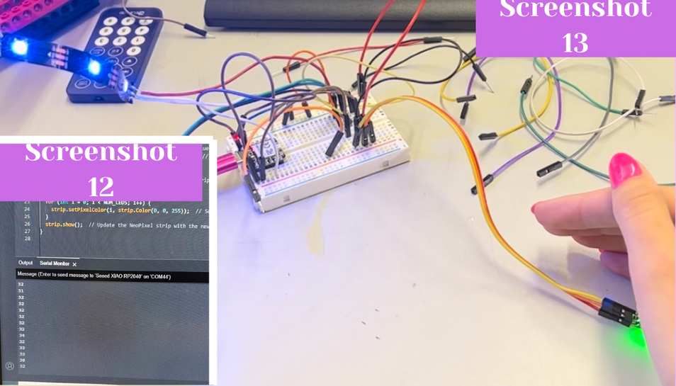 I did this by adding the three lines of brightness code into each
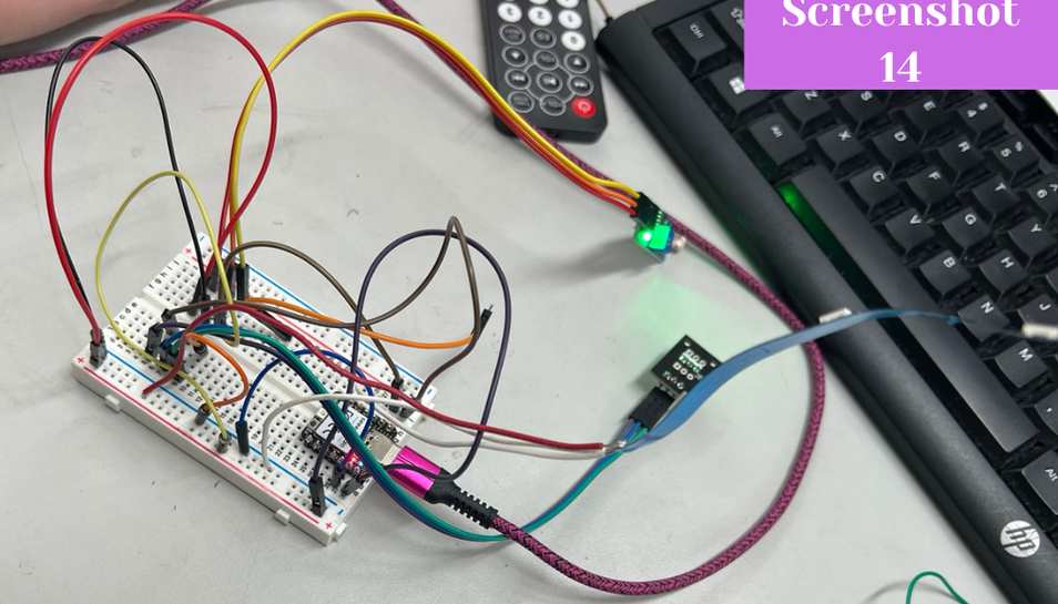
 case for the buttons and by adding #define PHOTO_PIN A1 to the top of the code. The wiring on my breadboard does look a little confusing (screenshot 14) but I did the following for ny wiring:
- RP2040 GND pin –> IR “G” pin, photoresistor GND pin, and NeoPixel GND pin
- RP2040 D0 pin –> IR “Y” pin (data pin)
- RP2040 A1 pin –> photoresistor “din” pin (data pin)
- RP2040 D4 pin –> NeoPixel “din” pin (data pin)
- RP2040 5V pin –> IR “R” pin (power), photoresistor 5V pin, and NeoPixel 5V pin
 This left me with the following code:
Working Combined Final Code
// Code partially from the Adafruit NeoPixel library code "simple", and from the following website: https://roboticsbackend.com/arduino-ir-remote-controller-tutorial-setup-and-map-buttons/
// Adapted and modified by Ginny Foster for Final Project during Fab Academy 2023

#include <IRremote.h>
#include <Adafruit_NeoPixel.h>

#define IR_RECEIVE_PIN D0

#define IR_BUTTON_1 12
#define IR_BUTTON_2 24
#define IR_BUTTON_3 94
#define IR_BUTTON_4 8
#define IR_BUTTON_5 28
#define IR_BUTTON_6 90
#define IR_BUTTON_7 66
#define IR_BUTTON_8 82
#define IR_BUTTON_9 74
#define IR_BUTTON_0 22
#define IR_BUTTON_EQ 25
#define IR_BUTTON_STRE 13
#define IR_BUTTON_PLAY_PAUSE 64

#define NUMPIXELS 50 // Number of NeoPixels in the strip
#define DATA_PIN D4 // Data pin for the NeoPixel strip
#define PHOTO_PIN A1 // Data pin for the photoresistor

Adafruit_NeoPixel pixels(NUMPIXELS, DATA_PIN, NEO_GRB + NEO_KHZ800);

#define DELAYVAL 100 // Time (in milliseconds) to pause between pixels

void setup() {
  Serial.begin(9600);
  IrReceiver.enableIRIn();
  pixels.begin();
}

void loop() {
  if (IrReceiver.decode()) {
    int command = IrReceiver.decodedIRData.command;
    switch (command) {
      case IR_BUTTON_1:
        Serial.println("Pressed on button 1");
        pixels.clear();
        int photoValue = analogRead(PHOTO_PIN);  // Read value from photoresistor
        int brightness = map(photoValue, 0, 1023, 0, 255);  // Map photoValue to brightness range (0-255)
        Serial.println(photoValue);
        pixels.setBrightness(brightness);  // Set NeoPixel strip brightness
        for(int i=0; i<NUMPIXELS; i++) { // For each pixel...
        pixels.setPixelColor(i, pixels.Color(245, 0, 87)); // pink
        pixels.show();
        break;
        }
      case IR_BUTTON_2:
        Serial.println("Pressed on button 2");
        pixels.clear();
        int photoValue = analogRead(PHOTO_PIN);  // Read value from photoresistor
        int brightness = map(photoValue, 0, 1023, 0, 255);  // Map photoValue to brightness range (0-255)
        Serial.println(photoValue);
        pixels.setBrightness(brightness);  // Set NeoPixel strip brightness
        for(int i=0; i<NUMPIXELS; i++) { // For each pixel...
        pixels.setPixelColor(i, pixels.Color(255, 0, 0)); // red
        pixels.show();
        break;
        }
      case IR_BUTTON_3:
        Serial.println("Pressed on button 3");
        pixels.clear();
        int photoValue = analogRead(PHOTO_PIN);  // Read value from photoresistor
        int brightness = map(photoValue, 0, 1023, 0, 255);  // Map photoValue to brightness range (0-255)
        Serial.println(photoValue);
        pixels.setBrightness(brightness);  // Set NeoPixel strip brightness
        for(int i=0; i<NUMPIXELS; i++) { // For each pixel...
        pixels.setPixelColor(i, pixels.Color(255, 61, 0)); // orange
        pixels.show();
        break;
        }
      case IR_BUTTON_4:
        Serial.println("Pressed on button 4");
        pixels.clear();
        int photoValue = analogRead(PHOTO_PIN);  // Read value from photoresistor
        int brightness = map(photoValue, 0, 1023, 0, 255);  // Map photoValue to brightness range (0-255)
        Serial.println(photoValue);
        pixels.setBrightness(brightness);  // Set NeoPixel strip brightness
        for(int i=0; i<NUMPIXELS; i++) { // For each pixel...
        pixels.setPixelColor(i, pixels.Color(255, 234, 0)); // yellow
        pixels.show();
        break;
        }
      case IR_BUTTON_5:
        Serial.println("Pressed on button 5");
        pixels.clear();
        int photoValue = analogRead(PHOTO_PIN);  // Read value from photoresistor
        int brightness = map(photoValue, 0, 1023, 0, 255);  // Map photoValue to brightness range (0-255)
        Serial.println(photoValue);
        pixels.setBrightness(brightness);  // Set NeoPixel strip brightness
        for(int i=0; i<NUMPIXELS; i++) { // For each pixel...
        pixels.setPixelColor(i, pixels.Color(139, 195, 74)); // green
        pixels.show();
        break;
        }
      case IR_BUTTON_6:
        Serial.println("Pressed on button 6");
        pixels.clear();
        int photoValue = analogRead(PHOTO_PIN);  // Read value from photoresistor
        int brightness = map(photoValue, 0, 1023, 0, 255);  // Map photoValue to brightness range (0-255)
        Serial.println(photoValue);
        pixels.setBrightness(brightness);  // Set NeoPixel strip brightness
        for(int i=0; i<NUMPIXELS; i++) { // For each pixel...
        pixels.setPixelColor(i, pixels.Color(0, 172, 193)); // light blue
        pixels.show();
        break;
        }
      case IR_BUTTON_7:
        Serial.println("Pressed on button 7");
        pixels.clear();
        int photoValue = analogRead(PHOTO_PIN);  // Read value from photoresistor
        int brightness = map(photoValue, 0, 1023, 0, 255);  // Map photoValue to brightness range (0-255)
        Serial.println(photoValue);
        pixels.setBrightness(brightness);  // Set NeoPixel strip brightness
        for(int i=0; i<NUMPIXELS; i++) { // For each pixel...
        pixels.setPixelColor(i, pixels.Color(41, 121, 255)); // blue
        pixels.show();
        break;
        }
      case IR_BUTTON_8:
        Serial.println("Pressed on button 8");
        pixels.clear();
        int photoValue = analogRead(PHOTO_PIN);  // Read value from photoresistor
        int brightness = map(photoValue, 0, 1023, 0, 255);  // Map photoValue to brightness range (0-255)
        Serial.println(photoValue);
        pixels.setBrightness(brightness);  // Set NeoPixel strip brightness
        for(int i=0; i<NUMPIXELS; i++) { // For each pixel...
        pixels.setPixelColor(i, pixels.Color(206, 47, 216)); // purple
        pixels.show();
        break;
        }
      case IR_BUTTON_9:
        Serial.println("Pressed on button 9");
        pixels.clear();
        int photoValue = analogRead(PHOTO_PIN);  // Read value from photoresistor
        int brightness = map(photoValue, 0, 1023, 0, 255);  // Map photoValue to brightness range (0-255)
        Serial.println(photoValue);
        pixels.setBrightness(brightness);  // Set NeoPixel strip brightness
        for(int i=0; i<NUMPIXELS; i++) { // For each pixel...
        pixels.setPixelColor(i, pixels.Color(106, 27, 154)); // light purple
        pixels.show();
        break;
        }
      default:
        Serial.println("Button not recognized");
        break;
    }
    IrReceiver.resume();
  }
}
When I tested this code it also worked as you can see in the video below.
So, my next step was to scale this from 3 NeoPixels to ~35 NeoPixels so that the strand could wrap all the way around my planned 3D printed NeoPixel holder.
Adding In an External Power Supply
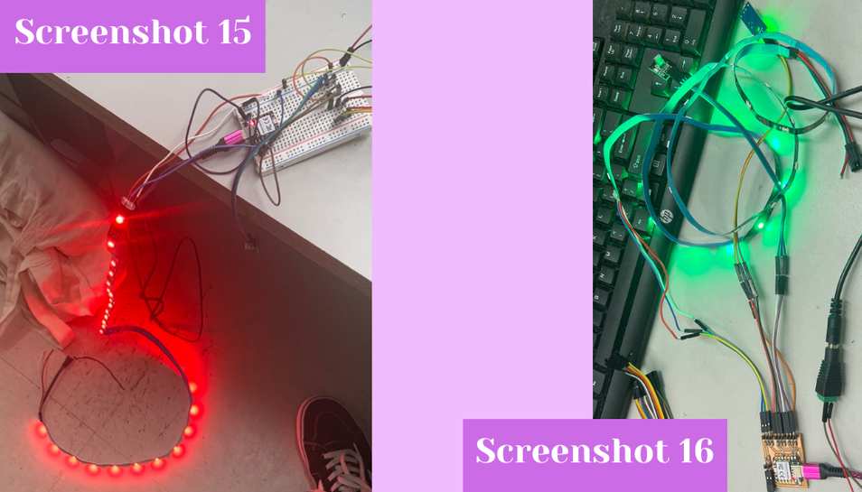
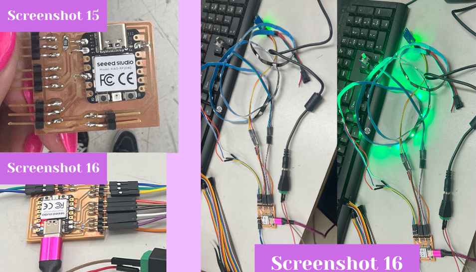
To expand from 3 NeoPixels to more than 30, I knew I needed an external power source because the SEEED Xiao RP2040 couldn’t supply enough current for many NeoPixels. To add the external power source I could refer back to my week 9: outputs board where I added in a power source to NeoPixels. I connected the 5V of the NeoPixels, the photoresistor, and the IR reciver to the power source which I plugged into the rail of the breadboard (screenshot 15). I then connected the ground pins of everything to ground of the external power supply, and also back to the GND pin of the SEEED Xiao RP2040 (screenshot 15). With all of that plugged in, I plugged in the external power supply to an outlet, and a USB-C cable to a brick and then to an outlet. From there I tried using the remote with the strip and it worked like it did when there were only 3 NeoPixels (screenshot 15). Once I knew that was working I could make a PCB for it.
Making a PCB
Designing the PCB
I decided to use Eagle in Fusion 360 to create my board for my final project. I went in and created a new electronics design from the file tab. I started by dragging out all schematic footprints I would need by searching for them in the left side picker and selecting on each component I wanted (screenshot 1). They are as follows:
- 1 Seeed Xiao RP2040
- 3 1x3 header pins
- 1 1x2 header pin
- 1 1206 SMD resistors
With all of the components dragged out, I began using the net tool from the top bar to connect the components together (screenshot 2). I used the net tool and clicked on each pin that I wanted to connect and it made a line between the selected pins; I did this for everything I wanted to connect (screenshot 2).
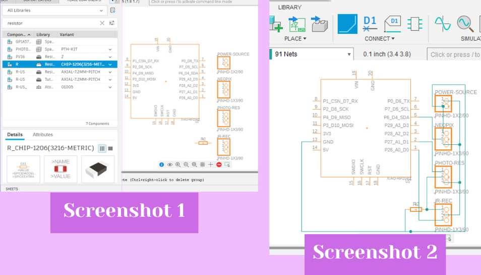 With everything netted I switched to the PCB editor by clicking on the PCB icon in the top left hand corner of the schematic editor. This opened up the PCB workspace and I began by arranging all of my components on the board and by clicking on and dragging in the boundaries of the PCB workspace (screenshot 3). My goal was to have a very small PCB because everything needed to fit into the middle of my lamp, and the board was nearly 2” x 2” so I think this was very successful. Next, I used the manual route tool from the top bar to connect each pad of the footprints together (screenshot 4, blue box). I upped the trace width to 20 mil (screenshot 4, left side) and then clicked on each pad and drew the traces (screenshot 4).
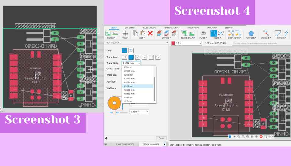 With everything routed and traces made (screenshot 5), I exported my file as a gerber by going to the manufacture tab and clicking on that option (screenshot 6).
- My PCB Design .brd
- My PCB Design .f3z
- Board Schematic .sch
- Board Top .png
- Board Profile .png
- Board Top and Profile .gbr (gerber)
Milling the PCB
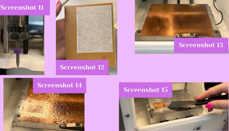
I downloaded my file from our lab’s Google Drive and then went into the Bantam milling software to mill the board. I used a large piece of Nitto tape to affix a piece of FR1 to the mill bed (screenshots 12 and 13). I stuck with the preset file setup for dimensions and thickness for FR1 boards and uploaded my gerber files for the copper top and the profile (screenshot 7). I then picked the bits I was going to use from the drop downs (screenshot 9) and then I used the “generate GCODE now” button to turn the gerber file into GCODE that the machine could read (screenshot 8). I then input the plan offset which is how far from the origin point you want your job to mill, so for example setting it to 0, 0 might be a bad idea because you might mill too close to the edge, and placing a design in the center of a new FR1 board would be wasteful, so I set mine slighlty off the corner edge to 7, 7 (screenshot 10).
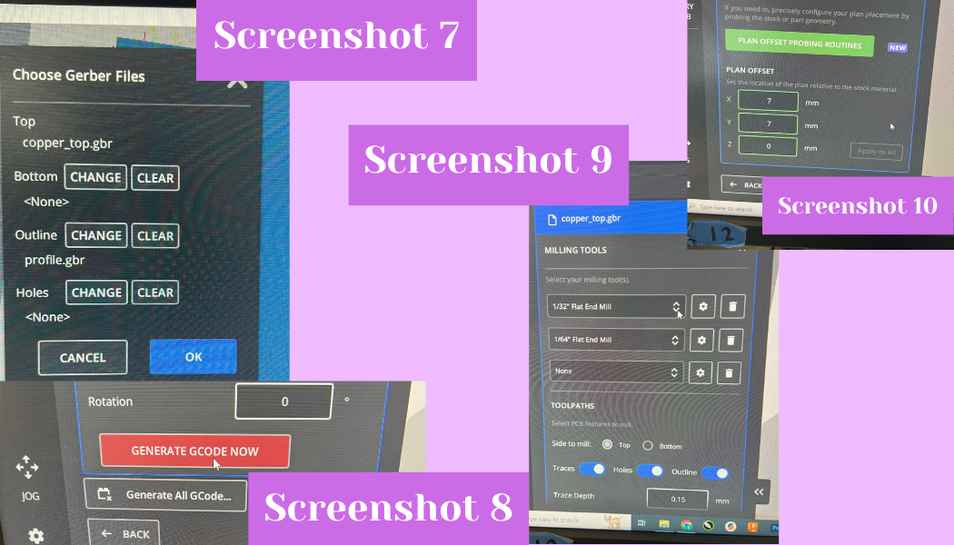 From there I installed a 1/64” two flute up cut flat endmill bit and then milled the file (screenshot 11). The job stopped about halfway through to change bits to the 1/32” two flute up cut flat endmill for the edge cut and larger areas of the design. After it was done milling (screenshot 14) I pried the FR1 up from the bed using a putty knife (screenshot 15), and then I soldered my components to the board. The components list is as follows:
- 1 SEEED Xiao RP2040
- 3 group of three surface mount header pins
- 1 group of two surface mount header pins
- 1 0 ohm SMD resistor
From there I installed a 1/64” two flute up cut flat endmill bit and then milled the file (screenshot 11). The job stopped about halfway through to change bits to the 1/32” two flute up cut flat endmill for the edge cut and larger areas of the design. After it was done milling (screenshot 14) I pried the FR1 up from the bed using a putty knife (screenshot 15), and then I soldered my components to the board. The components list is as follows:
- 1 SEEED Xiao RP2040
- 3 group of three surface mount header pins
- 1 group of two surface mount header pins
- 1 0 ohm SMD resistor
Testing the PCB board
With everything soldered onto my board (and no traces ripped!!), I proceeded with testing the board to ensure it worked (screenshot 15, picture below). I plugged all of my electronic inputs and outputs into the header pins, and then I uploaded my final combined code onto the SEEED Xiao RP2040 (screenshot 16, left). I then plugged in the external power source to the board, and into the wall. Finally, I plugged in the USB-C to a brick and then into the wall. I then used the remote and the NeoPixel turned on, changed brightness, and changed color! (screenshots 16, right side) Now that I had all of my electronics working I moved onto the physical aspects of my project.
Making The Outside Housing
To make the outside of my project that the light would shine through I first needed a box for the outside. I was originally going to make a tabbed box, but on my desk I’ve had a box made by one of my friend’s moms which has held some pens and pencils and has a 1920s cutout design on it, and I though that it would be interesting if I could adapt that for my final project. I started by asking her where she found the file because I was there when she cut it for me and I remember that she did not make the file. I learned that she found the file from a post on GlowForge’s user forum for someone that made a Frank Llyod Wright inspired candle holder/lantern. I downloaded the file, and decided that I would both change out the design on the sides of the box, that I would add in slots to the bottom for an acrylic slide which would diffuse the NeoPixel light so that you couldn’t see through directly to the NeoPixels, and that I would add a lid to the design so that I can’t see directly into the top of my lantern. I started doing this in Cuttle where I imported the candle holder/lantern design inside of a new design (screenshot 1). I then dragged out five rectangles from the side menu (screenshot 2). One I made 3.9” x 3.9”, two I made 4.0” x 4.9”, and the other two I made 4.9” x 4.2” using the type in dimension boxes (screenshot 3). The square would be the top panel, and the other four pieces would be the diffuser that would go behind the cut out design but infront of the electronics.
 I then added .125” tab holes in the bottom part of the box design (screenshot 4), as well as to the tops of the outside of the pattern pieces and the little rectangles with notches (screenshots 5).
 Finally, I added tabs to the rectangles I dragged out so that they would slot into the bottom piece like the patterned pieces do (screenshot 6). The next step was to export the file and open it in CorelDraw so I could replace the patterns and use the segment delete tool on the tabs where needed. I exported the file from cuttle by hitting file and then the export .svg option (screenshot 7).
 From there in CorelDraw I clicked on file and then open to open my cuttle file in CorelDraw. Next, I went online and found four patterns I liked for the patterns in the side of my lantern. I then opened each pattern in CorelDraw by clicking on file and then open. Once they were in CorelDraw, I traced bitmaps of each of the patterns. I did this by hitting the bitmaps button from ther top bar and then by clicking on outline trace (screenshot 8). From there I clicked on line art because I only needed the lines of each pattern as I was cutting them out (screenshot 8, red circle). In the settings tab of the convert to bitmap dialog box I adjusted the detail, smoothing, and corner smoothness of each pattern so that the pattern looked good and was not too distorted (screenshot 9). Next, in the colors tab, I changed the number of colors of each down to two colors by changing the number in the number of colors box (screenshot 10). After doing that I clicked ok, and the original image was deleted and I was left with a vector image of my pattern.
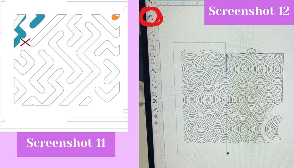
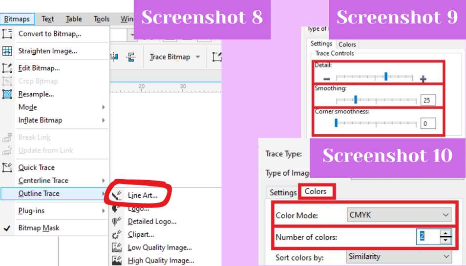 The next thing I did was deleted the original pattern that the box design came with, and I replaced it with each of the patterns I traced bitmaps of (screenshot 11 and 12). I also enlarged each pattern so that it would be large enough to cut in the laser cutter without a problem (screenshot 12). I used the segment delete tool to cut away the excess parts of the pattern (screenshot 12, red circle).
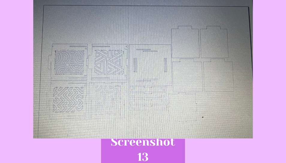
 Next, I used the segment delete tool to get rid of the lines were I added tabs to parts of the design. This left me with my final design which I first cut on cardboard (screenshot 13).
Laser Cutting Housing
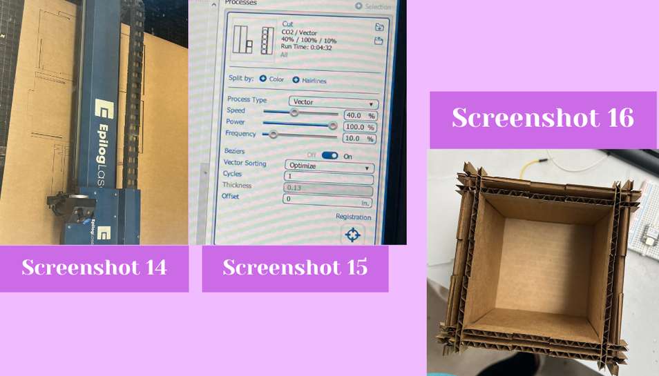
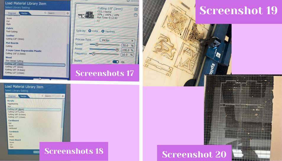
I first used cardboard to ensure my design would work before I actually used wood and acrylic. I loaded a piece of 18” x 25” cardboard into the largest laser cutter in our lab. I downloaded my file and then hit print on it to send it to the epilog interface. Inside the interface I imported the standardized settings for cutting on cardboard (speed: 40%, power: 100%, frequency: 10%) and I hit autofocus (screenshot 15). From there I hit print in the bottom right corner and then I hit the play pause button on the laser cutter to cut the file (screenshot 14). After it finished I took everything out and began assembling the box. I started by putting in the outer pieces with the patterns, followed by the solid inner walls, and finally the top skinny pieces and the lid. Everything fit together well after I put it together (screenshot 16) so I decided that I could proceed with cutting on wood and acrylic.
 I started by placing 1/8” wood into the laser cutter bed. I then went into my design and removed the pieces that I would be cutting on acrylic and then clicked print in CorelDraw. Inside the epilog interface I hit autofocus and imported the standardized settings for 1/8” wood (speed: 20%, power: 100%, frequency: 10%) and then hit print to send the file to laser cutter (screenshot 17). I hit the play button on the laser cutter and it cut the wooden pieces for my design (screenshot 19). After it was done, I took the wood and my cut pieces out and inserted a piece of 1/8” clear acrylic. I removed everything that was cut from wood in my design and left only the piece I needed cut from acrylic. Then I hit print to send it to the epilog interface where I imported the standardized settings for 1/8” acrylic, then I hit autofocus, and finally print to send it to the laser cutter (screenshot 18). Next, I hit play on the laser cutter and it cut my acrylic pieces (screenshot 20). After it was done I removed the acrylic and my pieces from the laser cutter.
Housing Aesthetic Elements
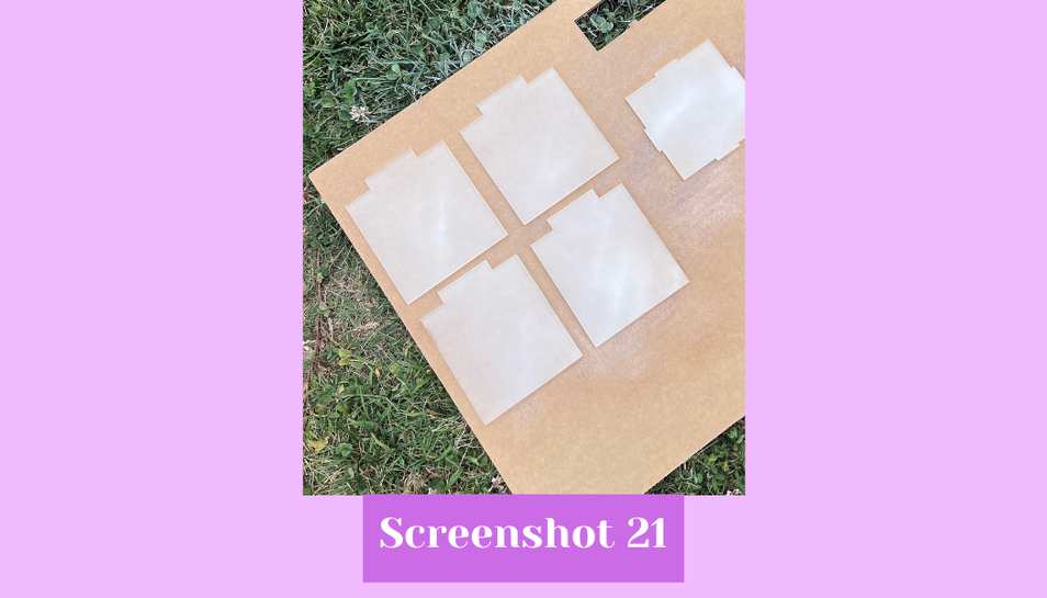
With my acrylic cut I could use glass frosting spray paint to make the clear acrylic hazy. I sprayed on three coasts of the Krylon Frosted Glass spray paint so that light could be seen through it but you couldn’t see anything obviously through the acrylic (screenshot 21). This was to disguise the electronics behind the acrylic pieces but still have the NeoPixels shine through.
- My CorelDraw Outer Box .cdr
- My CorelDraw Outer Box .svg
- My Cuttle Outer Box .svg
- The images I used for my final box patterns
Making the NeoPixel Holder
The final part of my final project is going to be making something that can both conceal my electronics and allow the NeoPixels to be held up and evenly spaced inside my lantern. I decided to do this by making a CAD designed and 3D printed open top box in Fusion 360.
Design
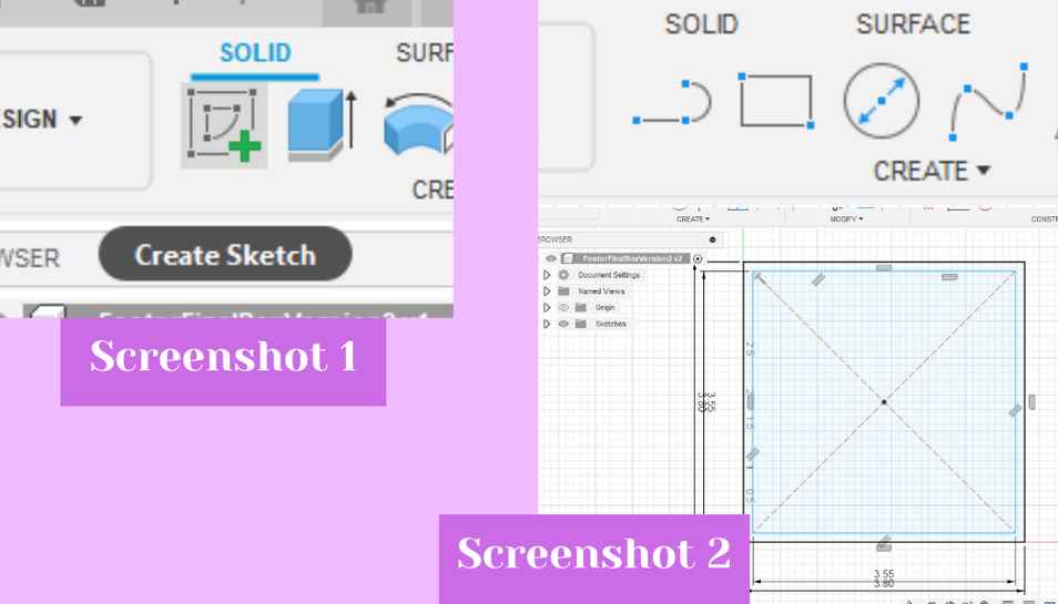
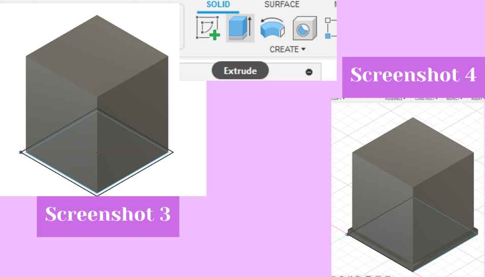
I in a new design workspace by creating a sketch from the top bar on the bottom XY plane (screenshot 1). I made a 3.55” x 3.55” square and then I hit shortcut letter “e” to extrude up the box (screenshot 2 and 3). I extruded the box up 4.15”. From there I made another sketch on the bottom XY plane of a 3.8” x 3.8” square which is .25” inches larger than the box I just made (screenshot 2).
 I then also hit “e” to extrude up the larger box, but I only extruded this up 0.25” (screenshot 4).
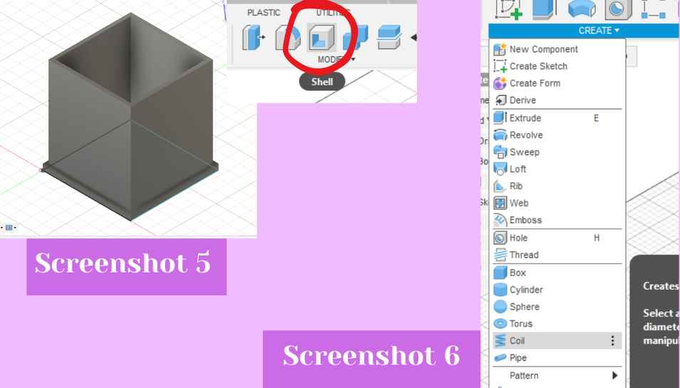
 Next, I used the shell tool from the modify toolbar to make the inside of the boxes I just made hollow (screenshot 5, red circle). I shelled the boxes .15” (screenshot 5). To add the little shelves to hold the NeoPixels, I decided to use a premade shape tool from the create drop down (screenshot 6). I picked the coil tool which allows you to easily make a spiral shape (screenshot 6).
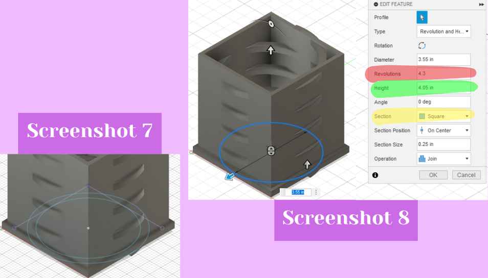
 I started by creating a sketch on the bottom XY plane of two circles inscribed within the boxes I made so that I had reference points for my coil (screenshot 7). Next, I activated the coil tool and began by first placing the center of the coil and then the outermost part of the circle. From there I changed the coil shape (called section) from a circle to a square because I needed a shelf that the NeoPixels could actually sit on without falling off (screenshot 8, yellow highlight). Next, I adjusted how many revolutions the coil made to 4.3 (screenshot 8, red highlight), then set the height to 4.05” (screenshot 8, green highlight), and then I clicked ok to create the coil.
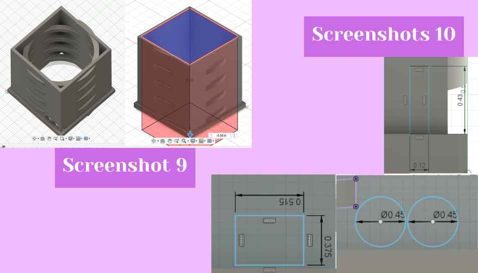
 Next, I made a sketch on the top area of the box I made so that I could extrude it down to cut away the parts of the coil that were inside the box because I needed that room for my electronics (screenshots 9). Finally, I made three sketches on the sides of my box for electronics holes. One was a 0.12” x 0.43” rectangle for the NeoPixel strip to come out of, a .0375” x 0.515” rectangle for the IR receiver, and the other was two circles with a 0.45” diameter next to each other for the power supply cord and the USB-C cord to come out of (screenshots 10).
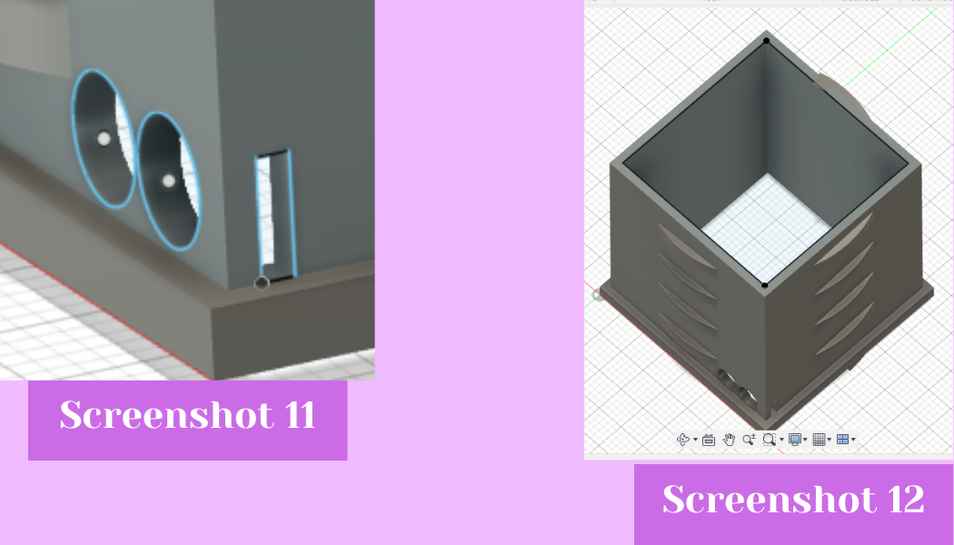
 I then intruded these holes into the wall of the box so they reached the interior area (screenshot 11). I also made a small clip in this design, but it was not for my final project, just something I needed to fix a personal project. With that I was done with my box design and was ready to print (screenshot 12).
3D Printing
The next step was to 3D print my design. I exported it as an .svg and opened it in Prusa Slicer. Once inside Prusa Slicer, I knew I needed supports for my coils, so I decided to use the paint on supports tool to achieve this because I didn’t need supports everywhere. I clicked on the paint bush icon from the left side bar (screenshot 13, red circle) and then in the dialog box that popped up I clicked on the smart fill option which allowed me to click on the underside of each coil to add supports there (screenshot 13). After I did this for all of the coil bottoms, I also did it for the electronics holes I made (screenshot 13). I then chose .20 mm SPEED for my print settings and 10% infill (screenshot 15). Finally, I clicked on the generate G-code button to make the G-code for my box. It then gave me a preview of the object and how long it was going to take to print, which was 8 hours (screenshot 14).
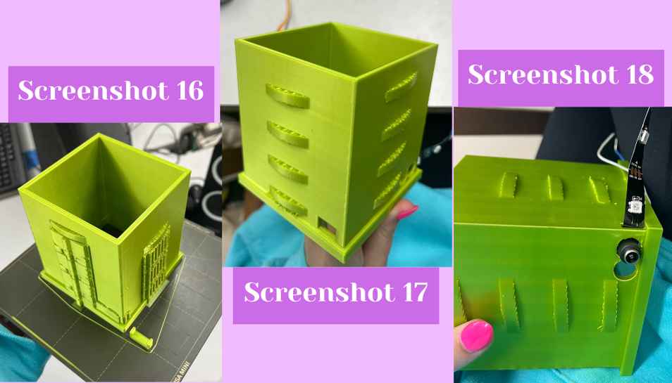
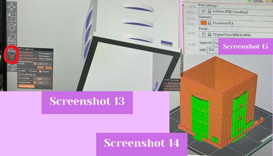 To print it I clicked on export G-code and then went to one of my lab’s printer specific websites to upload my file and print it. I chose printer 13 and used the upload button to pick my file, then after I wiped down the bed with alcohol, I clicked on the little printer icon to print the file. I then had to wait until it was done printing, and the next morning when I came in to the lab, it was finally done. I picked up the printer bed to remove my box as the printer bed is flexible and can be manipulated to break off 3D prints (screenshot 16). Next, I used a putty knife to help me break off the supports as they tend to be a little difficult to peel off. Once I had the supports removed (screenshot 17), I checked to make sure that my NeoPixels would fit through the hole I made them, and that the power supply would also fit (screenshot 18). They both did so I knew that my box would work for what I needed.
Final Assembly
Remote Stickers
To make my remote more customized, not as boring, and more user friendly, I decided to make some vinyl stickers to cover the base of the remote and all of the numbers, symbols, and words that do not pertain to my project. I measured the remote and started by making a rounded corner rectangle from the preset shape options in Silhouette Studio (screenshot 1). I then measured the diameter of one of the buttons and made a .34” x .34” circle also using the preset shapes menu (screenshot 2).
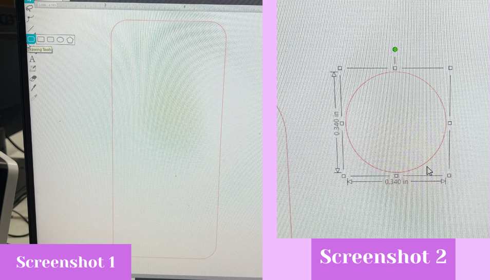 From there I gathered strips of vinyl sticker in the colors I wanted and stuck them down to a sticky mat for my lab’s vinyl cutters. I then copied the button circle a number of times and arranged the circles on the workspace in accordance to the position of the pieces of vinyl I made (screenshot 3). Next, I switched to the send tab on the right side of the workspace and selected Vinyl, Glossy as my material so it would have the correct cut settings for the material (screenshot 4).
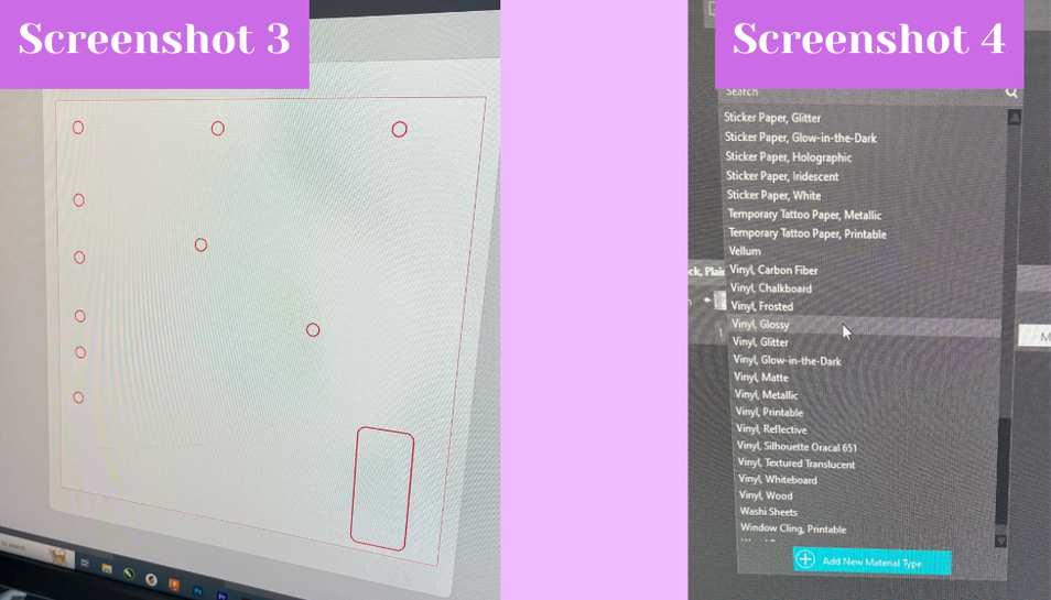 I then loaded the cut mat and hit send so the vinyl would cut (screenshot 5 and 6).
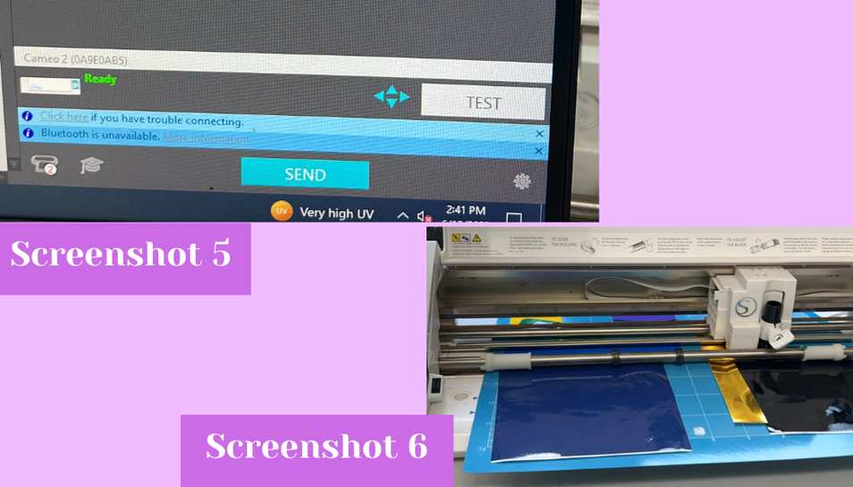 Afterwards, I used a pair of tweezers to apply the vinyl to the remote. (screenshot 7)
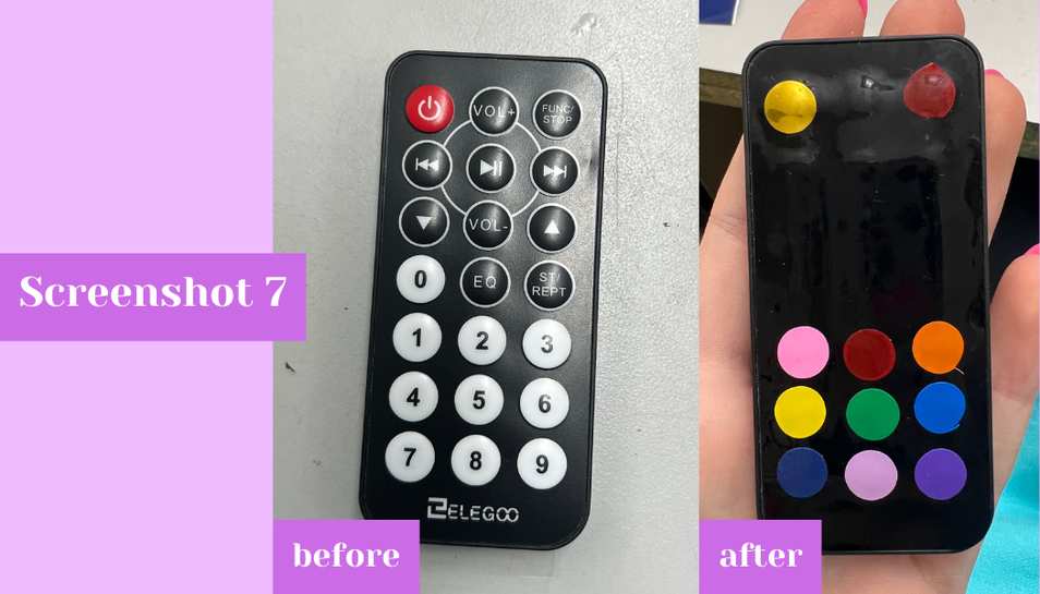
Box Assembly
Finally it came time to assemble my box. I started by realizing that I did not cut holes in the acrylic or wooden outside pieces of my box for the wires to go through so I made marks on each piece which needed another hole cut in it so I would know where to position them when I re-laser-cut them. I needed two holes for the power supply and the USB-C in both a pieces of acrylic and wood, a hole for the IR receiver in one of the acrylic pieces, and also a hole for the photoresistor in the top wooden piece. I quickly made each of the shapes I needed to cut in CorelDraw using the preset shapes tool (screenshot 7, red and green circles). The circles were .34” x .34” and the rectangle for the IR receiver was .2” x.245” (screenshot 7) and everything was set to hairline so it would cut not engrave (screenshot 8).
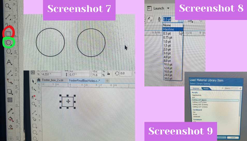 - My CorelDraw Outer Box Holes .cdr
- My CorelDraw Outer Box Hole .svg
- My CorelDraw Outer Box Holes .cdr
- My CorelDraw Outer Box Hole .svg
I then put each piece I needed in the laser cutter (screenshot 10), clicked the print button to print each design, imported either the 1/8” wood or acrylic setting depending on which material I was cutting (screenshot 9, see above picture), and then hit send and the play button to cut the design. I cut the acrylic first and then the wooden pieces and was left with perfect holes for each part I needed them for (screenshot 11).
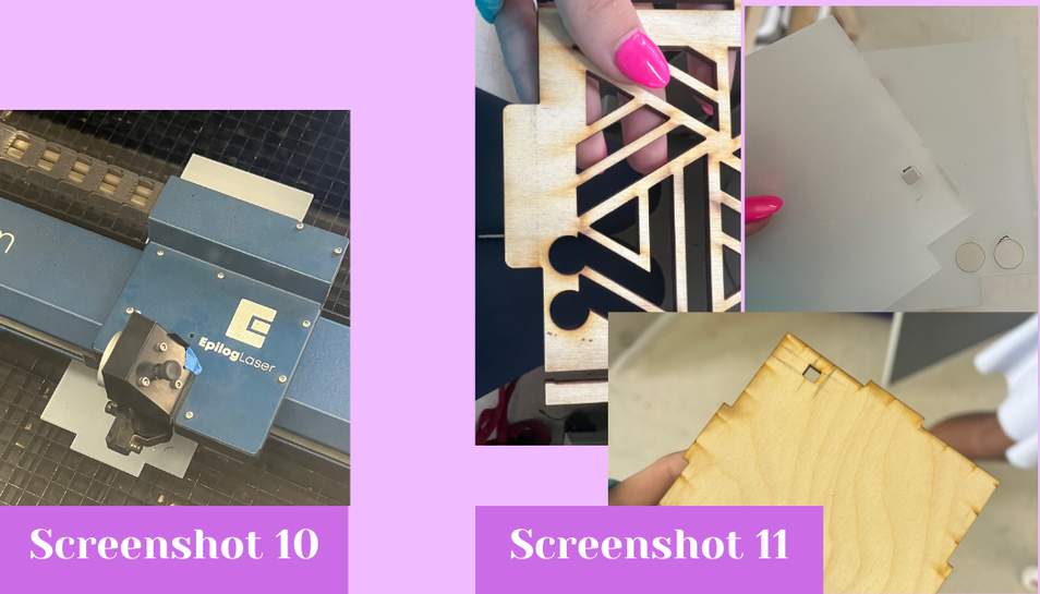 I then could proceed with the assembly. I started by putting two pieces of the outer box by slotting in each side to the bottom piece (screenshot 1). I then slide the other two sides of the out box into the bottom piece and into the first two sides (screenshot 2). I then inserted the acrylic pieces into the bottom behind the outer wood pieces (screenshot 3).
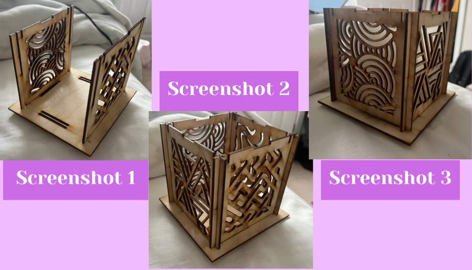 I then strung the NeoPixels around the outside of the NeoPixel holder, and peeling off a little bit of the sticky backing to affix the end of the strip to the top of the holder (screenshot 4). Next, I placed my PCB with the photoresistor, IR receiver, and end of the power supply attached into the inside of the NeoPixel holder (screenshot 5).
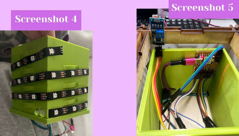 Next, I plugged in the power supply cord into the piece that was sticking through the side of the outer box to supply power, and I also fed through the USB-C cord and plugged it into the PCB board I made. Next, I situated the IR receiver into it’s hole in the acrylic so that it could receive commands from the remote properly and accurately. Finally, I placed the lid on the top of the box making sure that the photoresistor was properly sticking through the top of the box so it could read the ambient light of the environment its in. With that my lantern was assembled and all I had left to do was test it in its final form (screenshots 6). I used the remote to turn it on and change the colors and when I made it darker, or the room was darker, the NeoPixels got brighter as they should. In a bright environment the NeoPixels were dimmer as I expected, and with that I had finished my project (screenshots 6)(see final video for the lantern working in dark and bright environments and changing color).
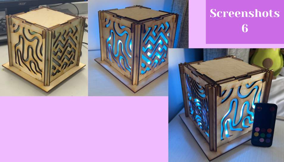 You can find a quick access to all of my files I made during this final project below.
You can also see my final slide and video below which I presented to Neil Gershenfeld during Fab Academy 2023 final project presentations on June 14th, 2023.
Video and Slide
Final Presentation Slide
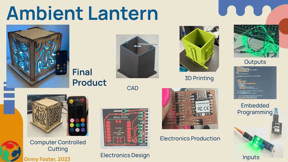
Final Presentation Video
All My Files
- My NeoPixel Holder .f3d
- My NeoPixel Holder .stl
- My PCB Design .brd
- My PCB Design .f3z
- My PCB Schematic .sch
- My PCB Top .png
- My PCB Profile .png
- My PCB Top and Profile .gbr (gerber)
- My CorelDraw Outer Box .cdr
- My CorelDraw Outer Box .svg
- My Cuttle Outer Box .svg
- My CorelDraw Outer Box Holes .cdr
- My CorelDraw Outer Box Holes .svg
- The images I used for my final box patterns
- My Sticker Design .studio3
- My Sticker Design .svg