4. Embedded Programming
This week I worked on using Arduino, a 412 chip, and a Raspberry Pi Pico to learn about C++, MicroPython, and bare metal programming/programming without libraries. With my group we discussed the architecture of different computer systems.
Group Work
You can see my work along with Dariyah Strachan, Dylan Ferro, Stuart Christhilf, and David Tian on the Charlotte Latin Fab Lab site for student group B. This week I helped fill out the chart that looked at the datasheet for our chip. From helping fill this chart out I learned that an ATTiny 1614 uses TinyAVR architecture which means you have to use a special programmer to upload code to it. I also learned that it has four 8-bit registers and can only be programmed using C and C++ programming languages. Finally, I learned that it has 14 PWM pins with a maximum operating voltage of 4.3 V, I could also see the SOIC pinout. The SOIC pinout revealed the identity of the pins. For example, pin 1 is the input supply pin or where you put power in, pin 14 is the ground pin, pin 10 is the UPDI pin, pins 2-13 are GPIO pins, and pins 2-5 and 8-13 are also analog pins. The datasheet for the ATTiny1614 can be accessed here.
Programming an Arduino
I’ve known how to program an Arduino for a few years now so this part of the assignment was a breeze compared to some other parts of this weeks assignment. I began by choosing what I wanted to do. I wanted to create what amounts to a light sensor that would turn on three lights depending on how much light is on the photoresistor. I began by using the blink sample code to create the program to only blink the three lights before adding in the photoresistor. I began by wiring together the three LEDs on a breadboard, connecting each to the pin and ground with a 383 ohm resistor between the LEDs and ground (screenshot 1). With everything wired, I began writing the code. I started this by defining the pins for each LED. Then inside the void setup() brackets I made each LED an output by writing pinMode(the-pin-number, OUTPUT);. After doing that inside the void loop() I wrote the commands to turn each LED on and off with pauses in between. After doing that I plugged my Arduino into my breadboard by connecting the 5V to the power rail, one of the ground pins to the ground rail, and pins of the Arduino to the LED. From there I complied and then uploaded my code to the Arduino. All of the lights worked first try so I felt like I then needed to test to make sure the photoresistor was reading values. I could also use these values to create the threshold for which light turn on at what value reading. To do this I began by putting my photoresistor into my breadboard away from my LEDs which I left in but not turned on and flashing. To one end of the photoresistor I connected a 10k ohm resistor and then from the resistor I added a wire to the ground rail. I then used a jumper wire from the other leg of resistor to connect it to the A0 pin of the Arduino because I need it to read analog values from the photoresistor. From there I found a simple code from this website to start the serial monitor and then read the values from the photoresistor. I found the code from this website. Then I uploaded the code to the Arduino using the compile button in the top left corner of the Arduino and then using the upload button located next to the compile button. Once I opened the serial monitor using the button in the top right corner I could see that there were values popping in the serial monitor. The code I used for this is below.
Photoresistor only test code
// Code found from: https://www.circuitbasics.com/how-to-use-photoresistors-to-detect-light-on-an-arduino/#:~:text=Photoresistors%20are%20analog%20sensors%20that,for%20making%20light%20controlled%20switches.
// Used during Fab Academy 2023 by Ginny Fotser
int photoPin = A0;

void setup() {
  Serial.begin(9600);
}

void loop() {
  int light = analogRead(photoPin);
  Serial.println(light);
  delay(100);
}
Next I connected everything together by combining the two codes I had. I essentially combined the defining of the pins at the beginning of the code and then also defined the values for the thresholds for each light to turn on. Next, inside the void setup() I combined the setting of each pin as an input or an output and the beginning of the serial monitor. From there I created the variable for the value of the photoresistor inside the void loop() and added that variable to print in the serial monitor. Next, I made four if statements for turning on and off each light or none of them depending on the value of the photoresistor. With that done I made sure all of it was wired correctly and then compiled and uploaded the code. It started on green because I was facing a bright open window and when I stood in front of the window which you can see as I got closer to the breadboard setup the lights go from yellow to red as I block out more of the light. You can find the code and videos below.
Final Arduino Code
// Code written by Ginny Foster during Fab Academy 2023
// I referenced code from this website to help writing the code: https://www.circuitbasics.com/how-to-use-photoresistors-to-detect-light-on-an-arduino/#:~:text=Photoresistors%20are%20analog%20sensors%20that,for%20making%20light%20controlled%20switches
// I also used the blink example code from the Arduino library

// Define the pin numbers for the LEDs and photoresistor
const int redPin = 8;
const int yellowPin = 9;
const int greenPin = 10;
const int photoPin = A0;

// Define the threshold values for the LEDs light levels
const int redThreshold = 80;
const int yellowThreshold = 150;
const int greenThreshold = 200;

void setup() {
  // Set the LED pins as outputs
  pinMode(redPin, OUTPUT);
  pinMode(yellowPin, OUTPUT);
  pinMode(greenPin, OUTPUT);
  // Begin the serial monitor
  Serial.begin(9600);
  // Set the photoresistor pin as an input
  pinMode(photoPin, INPUT);
}

void loop() {
  // Read the value of the photoresistor and print that value into the serrial monitor
  int photoValue = analogRead(photoPin);
  Serial.println(photoValue);
  // Wait 1 second
  delay(100);
  // Turn on the designated LED based on the light level as defined earlier by the thresholds
  if (photoValue < redThreshold) {
    digitalWrite(redPin, HIGH);
    digitalWrite(yellowPin, LOW);
    digitalWrite(greenPin, LOW);
  } else if (photoValue < yellowThreshold) {
    digitalWrite(redPin, LOW);
    digitalWrite(yellowPin, HIGH);
    digitalWrite(greenPin, LOW);
  } else if (photoValue < greenThreshold) {
    digitalWrite(redPin, LOW);
    digitalWrite(yellowPin, LOW);
    digitalWrite(greenPin, HIGH);
  } else {
    digitalWrite(redPin, LOW);
    digitalWrite(yellowPin, LOW);
    digitalWrite(greenPin, LOW);
  }
}
Programming an ATTiny 412 Chip Using Bare Metal Programming
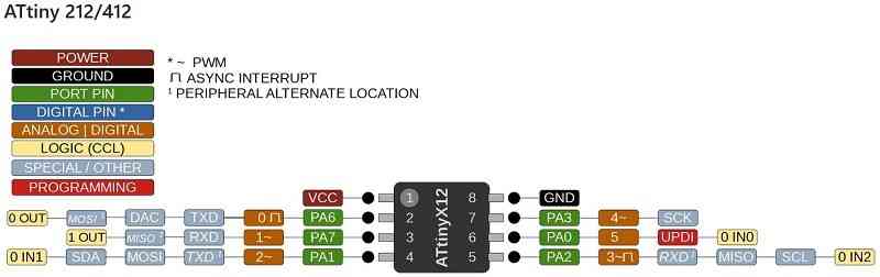
I began by listening to a lecture to BareMetal by Mr. Tom Dubick. He taught us the basics about BareMetal programming on the Arduino so we could use that example and apply it to an ATTiny412 chip. I first began by looking at the ATTiny 412 datasheet from here. The datasheet revealed the SOIC pinout which has since been adapted into a helpful pinout as seen below. The SOIC pinout identified the location of each pin and the pin’s purpose. For example, pin 1 is the input supply aka where you plug power in, and pin 8 is the ground pin, pins 2-7 are all GPIO pins, and pin 6 is the UPDI pin, finally pins 2-5 and 7 are all analog pins as well.
 From there I got started by wiring together my breadboard. I started by connecting the ATTiny pin 6 (aka the UPDI) to an Arduino pin 6. I then connected the 5v pin from the Arduino to pin 1 of the ATTiny 412 and the ground pin to pin 8 of the ATTiny, next I pushed in a gumdrop LED and a 330 ohm resistor to the breadboard. I connected the resistor to the negative side of the LED, the resistor to ground, and connected the positive side of the LED to pin 4 of the ATTiny 412. From there I wanted to make sure the Arduino was communicating with the ATTiny ok so I started uploading a blink code for pin 4. I changed the pin number of the blink example code for the analog/digital pin of pin 4 on the ATTiny which is 2. From there I uploaded it and it looked good so I proceeded with doing the BareMetal code.
// Adapted by Ginny Foster during Fab Academy 2023
// Adapted from the "blink" example in the Arduino library
void setup() {
  // initialize digital pin 2 as an output.
  pinMode(2, OUTPUT);
}

// the loop function runs over and over again forever
void loop() {
  digitalWrite(2, HIGH);  // turn the LED on (HIGH is the voltage level)
  delay(1000);                      // wait for a second
  digitalWrite(2, LOW);   // turn the LED off by making the voltage LOW
  delay(1000);                      // wait for a second
}
To switch that to BareMetal I first consulted Chatgpt and asked it to generate me a C++ code that blinked an LED connected to PA1. It gave me this exact code:
// Written by ChatGPT during Fab Academy 2023

#include <avr/io.h>
#include <util/delay.h>

#define LED_PIN PINA1

void setup()
{
  // Set PA1 as output
  PORTA.SET |= (1 << LED_PIN);
}

void loop()
{
  // Turn on the LED
  PORTA.OUT |= (1 << LED_PIN);

  // Wait for 1 second
  _delay_ms(1000);

  // Turn off the LED
  PORTA.OUT &= (1 << LED_PIN);

  // Wait for 1 second
  _delay_ms(1000);
}

int main()
{
  setup();

  while (1)
  {
    loop();
  }

  return 0;
}
It looked very similar to the code that Mr. Dubick had shown us as a model for blink code for an Arduino. I did make some changes to #define LED_PIN PINA1 because the varible was not really helpful and it was slightly wrong. I changed each varible from DDRA |= (1 << LED_PIN); to DDRA |= (1 << 1); because Mr. Dubick reviewed bit shifting with us and I knew I had to keep every other bit in port A off and only keep the bit connected to PA1 on. I also knew that the varible written was slightly off because PINA1, to my knowlege I dont think it the correct way to point to PA1. I also corrected the delay sections to delay(500);. From there I also removed the int main() section and the two #include libraries because they weren’t necessary. This left me with the following code.
// Written by Ginny Foster during Fab Academy 2023
// Adapted from code generated using ChatGPT by Ginny Foster
// Originial code can be found above

void setup()
{
  // Set PA1 as output
  PORTA.SET |= (1 << 1);
}

void loop()
{
  // Turn on the LED
  PORTA.OUT |= (1 << 1);

  // Wait for 1 second
  delay(500);

  // Turn off the LED
  PORTA.OUT &= ~(1 << 1);

  // Wait for 1 second
  delay(500);
}
I then uploaded this code after uploading the jtagudpi library to my arduino so that I turned my arduino into a programmer. The code worked which I was very surprised at since I had been putting this part of the week off for a long time. The LED would blink on and off with a half second delay in between each blink.
Programming a Raspberry Pi Pico using C++
I’ve only been using a Raspberry Pi Pico for about four or five months and I began to use it in my Electrical Engineering class taught by one of my instructors for Fab Academy, Mr. Tom Dubick. I am not super experienced with it but I know the basics. I know to use it you have to download the RP2040 library in Arduino in the library manager and also download something else, but if you need to know the full process I know that a fellow Fab Academy student from this year Adam Stone has some excellent documentation about the process. I began by connecting a micro USB cable to the Pico board and then while holding the white boot button down I plugged it into my laptop. I did not release the button until a file popped up called UF_2. Once that opened up I could hit the minus button of that tab, release the button, and then I could choose the Raspberry Pi Pico from the board selector drop down in the top left corner. With the board selected, I began by uploading the example code from the Arduino library by hitting file, examples, and then blink to flash the onboard LED and make sure everything was working as intended. When that code pulled up, I just hit the compile button in the top left corner and then the upload button in the top right to send it to the board. It started flashing, so I knew everything was working and functioning correctly. From there I transferred over the LEDs and photoresistor from the Arduino breadboard onto the breadboard with the Raspberry Pi Pico. I then wired the LEDs to pins 11, 12, and 13 for LEDs red, yellow, and green of the Pico and the photoresistor to pin 0 of the Pico. I found the pin values from page 129 of the beginner’s manual for using MicroPython with a Pico and the image is also below and the manual can also be downloaded at the bottom of the MicroPython section. From there all I had to do was copy over the Arduino code and update the pin numbers corresponding to where I had just connected the LEDs and photoresistor. Then I compiled and uploaded the code using the top two left buttons as mentioned above. It worked and the video can be found below along with the code. It is worth nothing that the photoresistor and lights were a little touchy/spasm-y but they did work.
Final Raspberry Pi Pico C++ Code
// Code written by Ginny Foster during Fab Academy 2023
// I referenced code from this website to help writing the code: https://www.circuitbasics.com/how-to-use-photoresistors-to-detect-light-on-an-arduino/#:~:text=Photoresistors%20are%20analog%20sensors%20that,for%20making%20light%20controlled%20switches
// I also used the blink example code from the Arduino library


// Define the pin numbers for the LEDs and photoresistor
const int redPin = 11;
const int yellowPin = 12;
const int greenPin = 13;
const int photoPin = 0;

// Define the threshold values for the LEDs light levels
const int redThreshold = 80;
const int yellowThreshold = 150;
const int greenThreshold = 200;

void setup() {
  // Set the LED pins as outputs
  pinMode(redPin, OUTPUT);
  pinMode(yellowPin, OUTPUT);
  pinMode(greenPin, OUTPUT);
  // Begin the serial monitor
  Serial.begin(9600);
  // Set the photoresistor pin as an input
  pinMode(photoPin, INPUT);
}

void loop() {
  // Read the value of the photoresistor and print that value into the serrial monitor
  int photoValue = analogRead(photoPin);
  Serial.println(photoValue);
  // Wait 1 second
  delay(100);
  // Turn on the designated LED based on the light level as defined earlier by the thresholds
  if (photoValue < redThreshold) {
    digitalWrite(redPin, HIGH);
    digitalWrite(yellowPin, LOW);
    digitalWrite(greenPin, LOW);
  } else if (photoValue < yellowThreshold) {
    digitalWrite(redPin, LOW);
    digitalWrite(yellowPin, HIGH);
    digitalWrite(greenPin, LOW);
  } else if (photoValue < greenThreshold) {
    digitalWrite(redPin, LOW);
    digitalWrite(yellowPin, LOW);
    digitalWrite(greenPin, HIGH);
  } else {
    digitalWrite(redPin, LOW);
    digitalWrite(yellowPin, LOW);
    digitalWrite(greenPin, LOW);
  }
}
Programming a Raspberry Pi Pico using MicroPython
To begin I unplugged the Raspberry Pi I was using for the Arduino part as mentioned above and then I downloaded Thonny, a coding app recommended by former Fab Academy grad and instructor Dr. David Taylor. I followed the setup instructions from a tutorial booklet Dr. Taylor gave us. To do this I plugged in the Pico while holding down the boot button, and then I changed the interpreter in the bottom right-hand corner
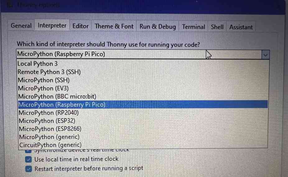
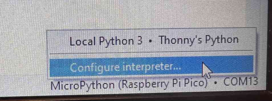 to the Micropython (Raspberry Pi Pico) from there I had to configure the interpreter so I clicked on that from the drop-down. I then selected MicroPython (Raspberry Pi Pico).
 From there I got stumped because once I clicked ok for the configuration but at the bottom box or the Python shell it told me:
Device is busy or does not respond. Your options:

  - wait until it completes current work;
  - use Ctrl+C to interrupt current work;
  - reset the device and try again;
  - check connection properties;
  - make sure the device has suitable MicroPython / CircuitPython / firmware;
  - make sure the device is not in bootloader mode.

Could not interrupt current process. Please wait, try again or select Stop/Restart!
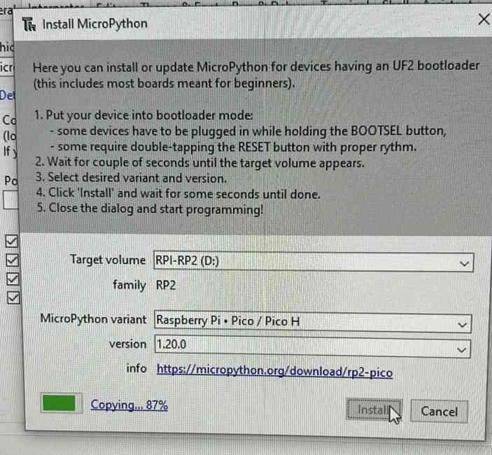
I was stumped and so I decided to do some googling to see if anyone else had the same issue. I eventually found this website which says “[Links to] download the correct MicroPython UF2 file for your board: Raspberry Pi Pico
Then go ahead and:
Push and hold the BOOTSEL button and plug your Pico into the USB port of your Raspberry Pi or other computer. Release the BOOTSEL button after your Pico is connected.
It will mount as a Mass Storage Device called RPI-RP2.
Drag and drop the MicroPython UF2 file onto the RPI-RP2 volume. Your Pico will reboot. You are now running MicroPython.”
This website basically told me that my issue was that I didn’t have Micro Python properly installed and set up.
After following those steps my Pico connected correctly and from there everything went by easily.
 I began by making sure the Pico was connected and working correctly by blinking the onboard LED. I got this code from page 48 of the beginner’s manual and pasted it into the workspace of Thonny. I then began wiring up a circuit to blink an LED using a button to fulfill the requirement to use an input and an output. I placed to button first and on the top left of the button I wired a 10K ohm resistor as my pull-down resistor; Below at the bottom left I connected a jumper wire to the power rail. Then on the top right side, I connected a jumper wire to pin __, and across from that on the bottom right I connected a jumper wire to the positive leg of my LED. I connected a 383 ohm resistor to the negative leg of my LED and then from that resistor I connected a jumper wire to the negative rail of the breadboard. To supply power and ground I connected jumper wires from the power (pin 40/VBUS) and ground pins (pins 3, 8, 13, 18, 23, 28, 33, or 38) to the positive and negative rails of the breadboard. With everything connected I began following the tutorial/lesson in the manual on how to code an LED to blink with a button. This lesson starts on page 55 and ends on page 57. I followed along with the instructions and the main takeaway was that spaces in Thonny really matter and have a big impact on what you code does. For the last part of the code:
 led_external.value(0) it needs to be outside of the loop but still part of the main code and to do this you just delete four of the spaces in front of the line which moves it outside the loop. If I didn’t do that when the button would be pushed the LED would flash on and off instead of just being steady on. With my code written and my board wired I hit the green play button aka the run button from the top bar of Thonny to send the code to my board. It worked as it should. The code for both, the videos, and the Pico manual can be found below.
Micro Python Onboard LED Test Code
// Written by Gareth Halfacree and Ben Everard and found in Raspberry Pi Pico Beginners Manual on page 48
// Used by Ginny Foster during Fab Academy 2023

import machine
import utime
led_onboard = machine.Pin(25, machine.Pin.OUT)

while True:
    led_onboard.value(1)
    utime.sleep(5)
    led_onboard.value(0)
    utime.sleep(5)
Micro Python Button LED Code
// Written by Gareth Halfacree and Ben Everard and found in Raspberry Pi Pico Beginners Manual
// Adapted by Ginny Foster during Fab Academy 2023

import machine
import utime
led_external = machine.Pin(0, machine.Pin.OUT)
button = machine.Pin(15, machine.Pin.IN, machine.Pin.PULL_DOWN)

while True:
   if button.value() == 1:
        led_external.value(1)
        utime.sleep(2)
   led_external.value(0)
Raspberry Pi Pico Beginners Manual File
Reflection
This week has been very helpful for improving my knowledge of programming. I have never been good at programming and still will actively avoid it because I’m more of a mechanical engineering person, but this week has definitely made programming seem a little bit less hard. I also learned how to use Thonny, something which I’ve never heard of or used before, and it was a pretty easy app to learn. I also got a little exposure to BareMetal programming which I learned about just this week, and is still a little confusing.