13. Networking and Communications
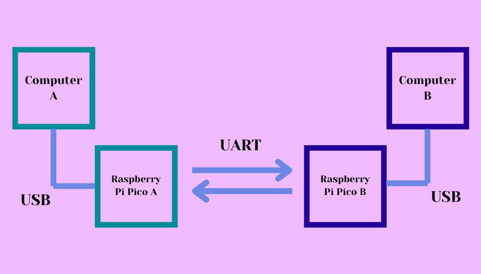
This week I used UART communication to communicate between two Raspberry Pi Pico W’s, and I used wireless communication on a Raspberry Pi Pico W to control a servo motor. I also designed and milled a PCB board for the UART communication. Finally, I worked with Ryan Kim to communicate with two Raspberry Pi Pico W’s to control the color of NeoPixels.
Group Work
This week I worked with Ryan Kim and we used to Raspberry Pi Pico W’s to send RGB values and then turn a NeoPixel different colors based of the RGB values one of the Pico W’s was receiving. I learned a lot about wireless communication and how to upload and configure wireless code from this group project and you can see more of what we did here.
Wired Connection with UART
Initial Testing
I began this week with no knowledge of what networking was, but through Neil’s lecture and the cheat sheet I was given by my instructor, I figured out enough to complete the assignment. I began by following a YouTube video on how to connect two Pico’s with UART. This video guided me through how to get two picos to speak to each other. I first tried it out on two Raspberry Pi Picos connected to breadboards and uploaded the easy_comms code to each board and then followed by pico_comms_a to one board and pico_comms_b to the other. After doing that I wired the TX(pico a) –> RX(pico b), RX(a) –> TX(b), and GND –> GND. Then I saw inside the shell in Thonny the two sending each other messages and then I knew that they were both working. With that I moved to integrate an output with UART communication.
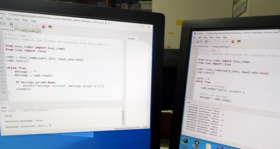
The shell of each Thonny window when the Pico were sending messages back and forth
Pico_comms_a code
// Code from this repo: https://github.com/kevinmcaleer/easy_comms
// Used by Ginny Foster during Fab Academy 2023

# Pico_comms_a
# Sends commands and listens to responses from pico_comms_b

from easy_comms import Easy_comms
from time import sleep

com1 = Easy_comms(uart_id=0, baud_rate=9600)
com1.start()

while True:
    message = ""
    message = com1.read()

    if message is not None:
        print(f"message received: {message.strip('\n')}")
    sleep(1)
Pico_comms_b code
// Code from this repo: https://github.com/kevinmcaleer/easy_comms
// Used by Ginny Foster during Fab Academy 2023

# Pico_comms_b
# Sends commands and listens to responses from pico_comms_a

from easy_comms import Easy_comms
from time import sleep

com1 = Easy_comms(uart_id=0, baud_rate=9600)
com1.start()

count = 0
while True:
    # send a message
    com1.send(f'hello, {count}')

    #check for messages
    message = com1.read()

    if message is not None:
        print(f"message received: {message.strip('\n')}")
    sleep(1)
    count +=1
Easy_comms code
// Code from this repo: https://github.com/kevinmcaleer/easy_comms
// Used by Ginny Foster during Fab Academy 2023

#Easy comms is a simple class that allows you to send and receive messages over a serial port.

from machine import UART, Pin
from time import time_ns

class Easy_comms:

    uart_id = 0
    baud_rate = 9600
    timeout = 1000 # milliseconds

    def __init__(self, uart_id:int, baud_rate:int=None):
        self.uart_id = uart_id
        if baud_rate: self.baud_rate = baud_rate

        # set the baud rate
        self.uart = UART(self.uart_id,self.baud_rate)

        # Initialise the UART serial port
        self.uart.init()

    def send(self, message:str):
        print(f'sending message: {message}')
        message = message + '\n'
        self.uart.write(bytes(message,'utf-8'))

    def start(self):
        message = "ahoy\n"
        print(message)
        self.send(message)

    def read(self)->str:
        start_time = time_ns()
        current_time = start_time
        new_line = False
        message = ""
        while (not new_line) or (current_time <= (start_time + self.timeout)):
            if (self.uart.any() > 0):
                message = message + self.uart.read().decode('utf-8')
                if '\n' in message:
                    new_line = True
                    message = message.strip('\n')
                    # print(f'received message: {message}')
                    return message
        else:
            return None
Making a Board
Now that I knew that the easy_comms library worked I made a board for the led_comms version. I started
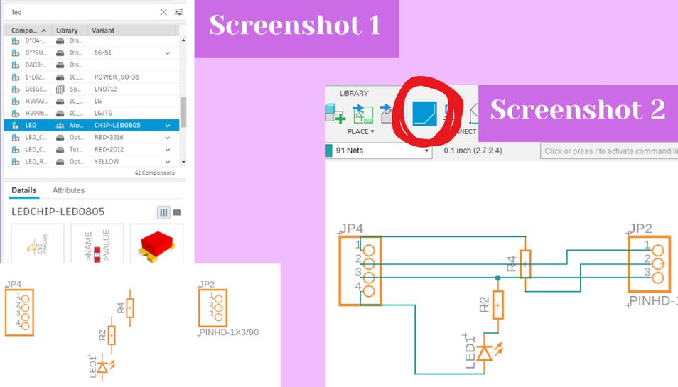
by creating a new electronics design from the file tab. I started by dragging out all schematic footprints I would need by searching for them in the left side picker and selecting on each component I wanted (screenshot 1). They are as follows:
- 1 1x3 header pin
- 1 1x4 header pin
- 2 1206 SMD resistors
- 1 LED SMD 806
With all of the components dragged out, I began using the net tool to connect the components together (screenshot 2, red circle).
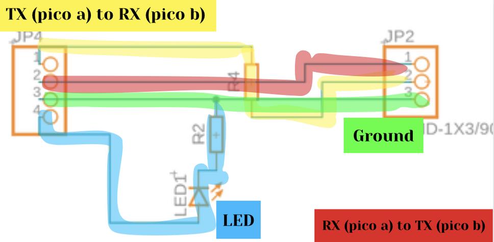
I used the net tool and clicked on each pin that I wanted to connect and it made a line between the selected pins; I did this for everything I wanted to connect (screenshot 2). There is also an annotated diagram showing the connections of everything below screenshots 1 and 2.
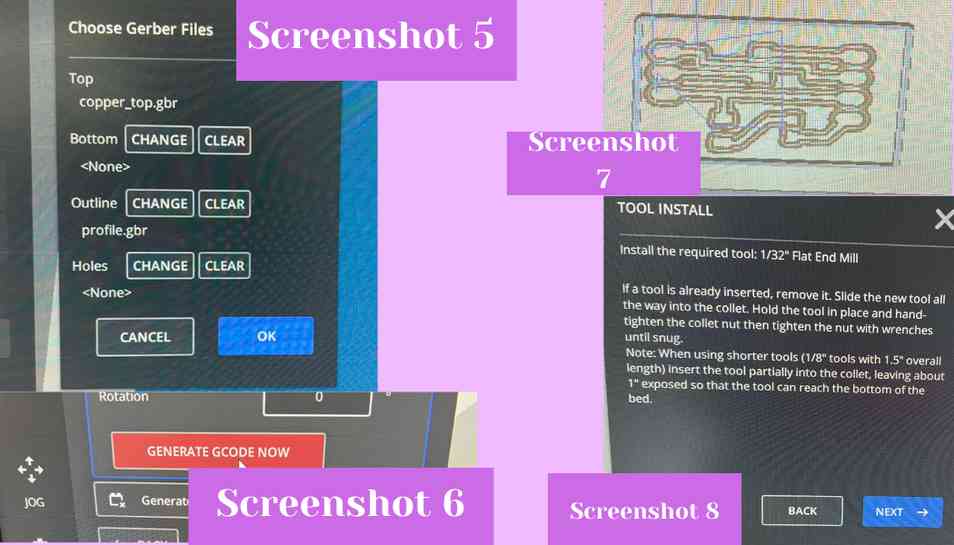
 With everything netted I switched to the PCB editor by clicking on the PCB icon in the top left hand corner of the schematic editor. This opened up the PCB workspace and I began by arranging all of my components on the board and by clicking on and dragging in the boundaries of the PCB workspace (screenshot 4). Next I used the manual route tool from the top bar to connect each pad of the footprints together (screenshot 5) and I upped the trace width to 20 mil (screenshot 3).
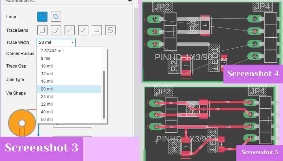 With everything routed and traces made, I exported my file as a Gerber by going to the manufacture tab and clicking on that option.
Milling the Board
I downloaded my file from our lab’s Google Drive and then went into the Bantam milling software to mill the board. I used a large piece of Nitto tape to affix a piece of FR1 to the mill bed. I stuck with the preset file setup for FR1 boards and uploaded my Gerber files for the copper top and the profile (screenshot 5). I then used the “generate GCODE now” button to turn the Gerber file into GCODE that the machine could read (screenshot 6). The GCODE displayed a preview of the file in the workspace and because it looked good I proceeded with the rest of the setup (screenshot 7). From there I installed a 1/64” two flute up cut flat endmill bit and then milled the file. The job stopped about halfway through to change bits to the 1/32” two flute up cut flat endmill for the edge cut and larger areas of the design (screenshot 8).
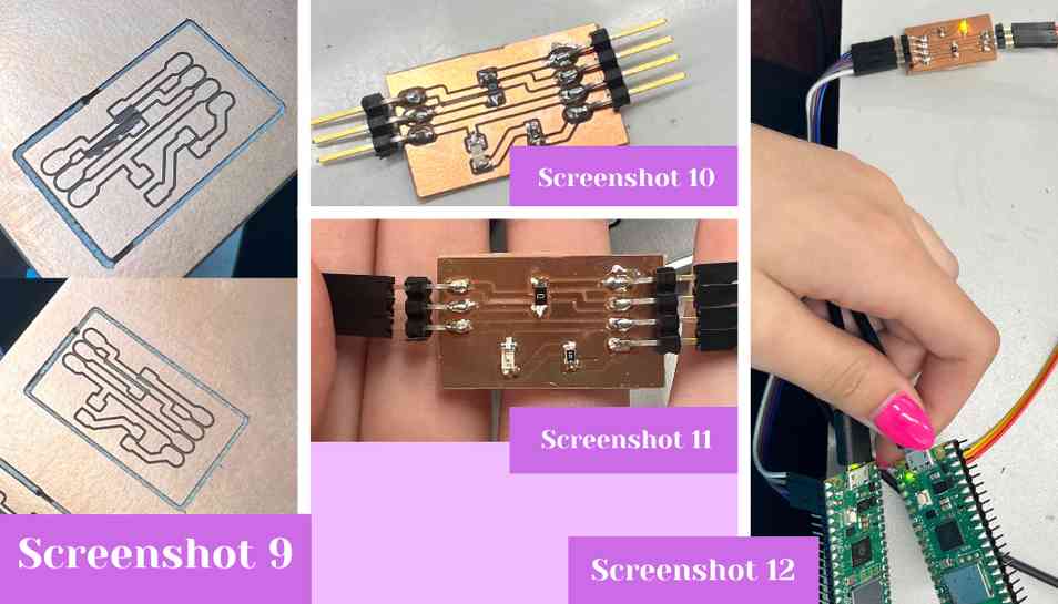
 After it was done milling I noticed that the trace that goes under the 0 ohm resistor was almost certainly ripped from the 1/64” endmill which I noticed, after taking it out, had some white stuff in the flutes of the bit (screenshot 9, top picture). I decided to then re-mill the file just to be sure that the trace wasn’t ripped, and this time I used a 0.005” PCB V shaped PCB engraving bit for the fine detail cutting. The second time around, the result looked much better (screenshot 9, bottom photo), so I pried the FR1 up from the bed using a putty knife. Next, I soldered my components to the board (screenshot 10). The components list is as follows:
- 1 group of three surface mount header pins
- 1 group of four surface mount header pins
- 1 orange LED
- 1 330 ohm SMD resistor
- 1 0 ohm SMD resistor
After I soldered everything together, I used ribbon female to female wires to connect the Pico W’s to the board I made (screenshots 11 and 12).
After it was done milling I noticed that the trace that goes under the 0 ohm resistor was almost certainly ripped from the 1/64” endmill which I noticed, after taking it out, had some white stuff in the flutes of the bit (screenshot 9, top picture). I decided to then re-mill the file just to be sure that the trace wasn’t ripped, and this time I used a 0.005” PCB V shaped PCB engraving bit for the fine detail cutting. The second time around, the result looked much better (screenshot 9, bottom photo), so I pried the FR1 up from the bed using a putty knife. Next, I soldered my components to the board (screenshot 10). The components list is as follows:
- 1 group of three surface mount header pins
- 1 group of four surface mount header pins
- 1 orange LED
- 1 330 ohm SMD resistor
- 1 0 ohm SMD resistor
After I soldered everything together, I used ribbon female to female wires to connect the Pico W’s to the board I made (screenshots 11 and 12).
Test LED UART
To test the board I first plugged a wireless Pico into my computer while pressing the boot button. I then opened a Thonny window and clicked on the configure interpreter button in the bottom right corner (screenshot 13). Next I clicked on “install or update micro python” (screenshot 14) which opened up a bottom pop up where I could select which Raspberry Pi board I was using which was a Raspberry Pi Pico W (screenshot 15).
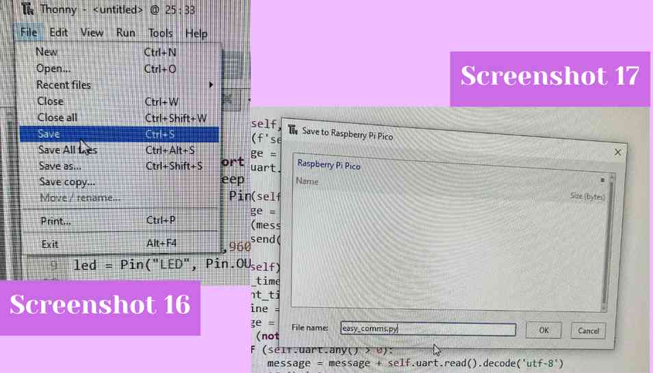
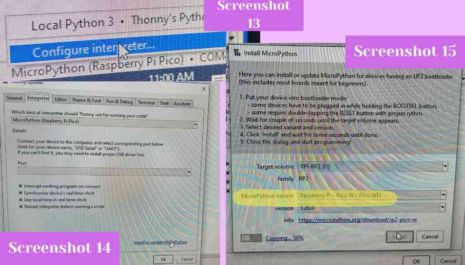 From there I did the same thing for a second Pico W board so that I had two Pico W boards connected to my computer. From there I saved the easy_comms library to each Raspberry Pi board by hitting “file” then “save” (screenshot 16) then “save to Raspberry Pi Pico” and then I entered a name for the file before saving it to the board (screenshot 17).
 I then ran the
 led_client on one Pico and led_server on the other. After hitting the green play run button on each window, the Pico’s began sending messages back and forth and the messages could be seen in the shell of each Thonny window. Additionally, the LED began blinking like it should in response to the Pico’s sending messages to each other.
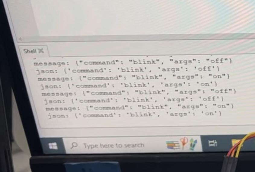
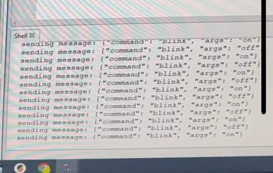 The two above images are taken from the video so that you can more easily see what’s happening in each shell, the top image is from the left shell and the bottom image is from the right shell
Wireless Connection
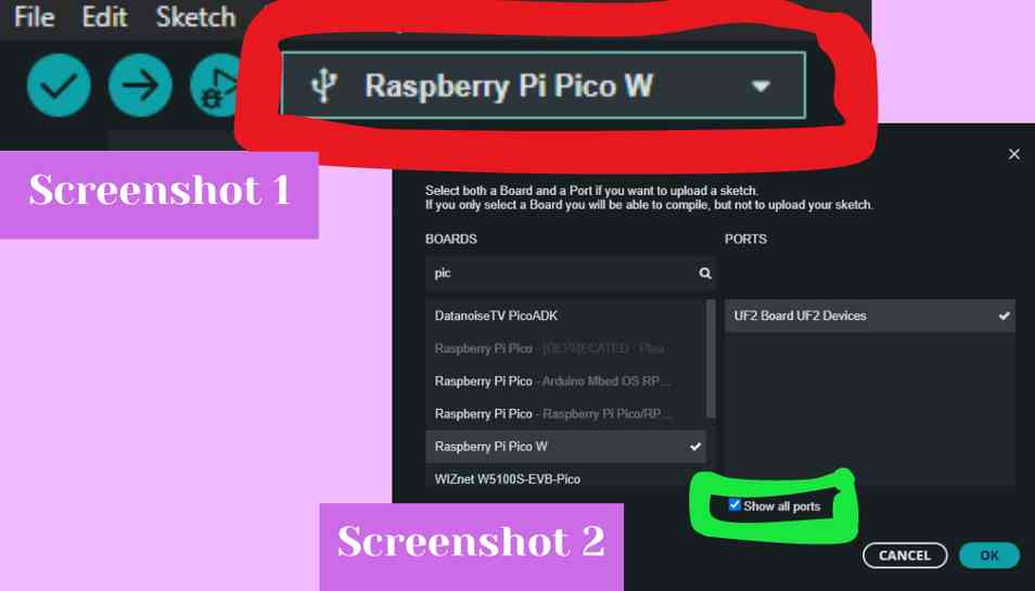
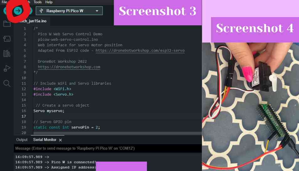
I started by finding this tutorial to help guide me through wireless communication with a Pico W. I started by connecting a small servo motor to the 5V, GND, and the GPIO 2 pin of a Raspberry Pi Pico W (screenshot 4, see below). From there I turned on my phone’s hotspot and then entered my phone hotspot SSID and password into the code. I then plugged in the Pico W into my computer while holding down the boot button. Then I went into the board selector in Arduino from the top bar (red circle, screenshot 1) and opened it and searched for the Pico W and then clicked on the show all ports box to selected the UF2 Board (green circle screenshot 2).
 From there I uploaded the code using the upload button (red circle screenshot 3).
 I then opened the serial monitor to see the status of the connection to my hotspot, but all it kept printing in the serial monitor was
 .’s. I looked in the code and it does this when it is trying to establish a connection to the network. I then realized that maybe my hotspot wasn’t working so I replaced that information with my WiFi SSID and password, and this time when I uploaded the code, the serial monitor said that it established a connection, and then it printed an IP address which when I copied into a browser opened up an interface which allowed me to drag my mouse across the screen and by doing this I could change the position of the servo arm (screenshot 5).
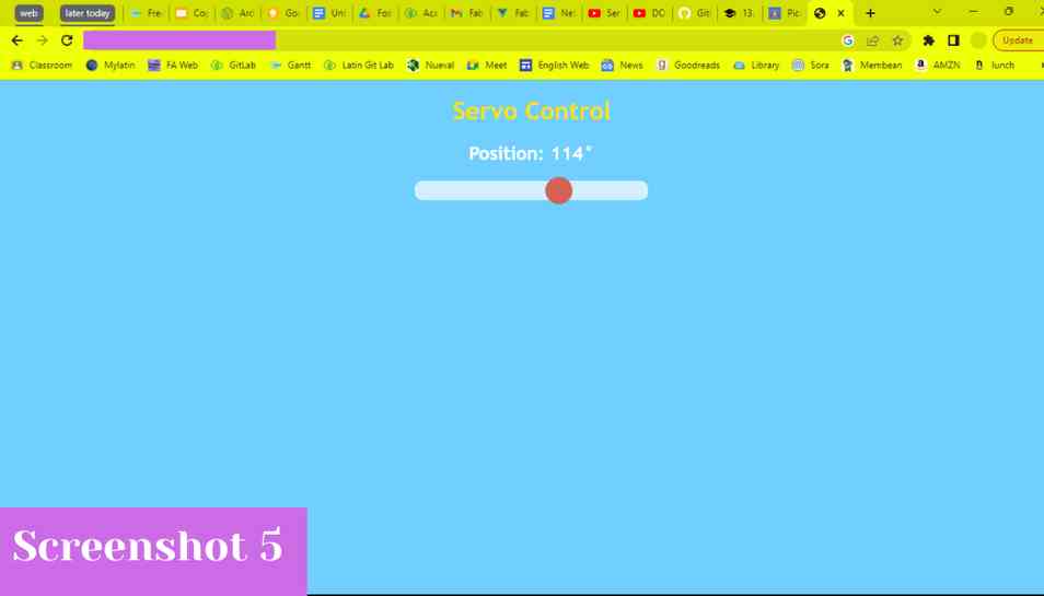 I then realized that the code created it’s own wireless back and forth with it’s self because the webpage that it gives in the serial monitor is like the client and the main code acts as a server which acts if it receives data from the client in the form of the slider bar being toggled. I found this was really interesting because I thought that for wireless communication you had to have two different microcontrollers talking to each other over a network and that you couldn’t do wireless communication with only one microcontroller because it could only perform on task. I think that using wireless communication like this would be really interesting and helpful to use in any interactive projects.
Wireless Code
/*
Pico W Web Servo Control Demo
picow-web-servo-control.ino
Web interface for servo motor position
Adapted from ESP32 code - https://dronebotworkshop.com/esp32-servo
DroneBot Workshop 2022
https://dronebotworkshop.com
*/
// Used by Ginny Foster during Fab Academy 2023
// Include WiFi and Servo libraries
#include <WiFi.h>
#include <Servo.h>
// Create a servo object
Servo myservo;
// Servo GPIO pin
static const int servoPin = 2;
// Network credentials
const char* ssid = "YOUR SSID";
const char* password = "YOUR PASSWORD";
// Web server on port 80 (http)
WiFiServer server(80);
// Variable to store the HTTP request
String header;
// Decode HTTP GET value
String valueString = String(5);
int pos1 = 0;
int pos2 = 0;
// Current time
unsigned long currentTime = millis();
// Previous time
unsigned long previousTime = 0;
// Define timeout time in milliseconds (example: 2000ms = 2s)
const long timeoutTime = 2000;
void setup() {
// Attach to servo and define minimum and maximum positions
// Modify as required
myservo.attach(servoPin, 600, 2400);
// Start serial
Serial.begin(115200);
// Connect to Wi-Fi network with SSID and password
WiFi.begin(ssid, password);
while (WiFi.status() != WL_CONNECTED) {
delay(500);
Serial.print(".");
}
// Print local IP address and start web server
Serial.println("");
Serial.println("Pico W is connected!");
Serial.print("Assigned IP address: ");
Serial.println(WiFi.localIP());
server.begin();
}
void loop(){
// Listen for incoming clients
WiFiClient client = server.available();
// Client Connected
if (client) {
// Set timer references
currentTime = millis();
previousTime = currentTime;
// Print to serial port
Serial.println("New Client.");
// String to hold data from client
String currentLine = "";
// Do while client is connected
while (client.connected() && currentTime - previousTime <= timeoutTime) {
currentTime = millis();
if (client.available()) { // if there's bytes to read from the client,
char c = client.read(); // read a byte, then
Serial.write(c); // print it out the serial monitor
header += c;
if (c == '\n') { // if the byte is a newline character
// if the current line is blank, you got two newline characters in a row.
// that's the end of the client HTTP request, so send a response:
if (currentLine.length() == 0) {
// HTTP headers always start with a response code (e.g. HTTP/1.1 200 OK) and a content-type
client.println("HTTP/1.1 200 OK");
client.println("Content-type:text/html");
client.println("Connection: close");
client.println();
// Display the HTML web page
// HTML Header
client.println("<!DOCTYPE html><html>");
client.println("<head><meta name=\"viewport\" content=\"width=device-width, initial-scale=1\">");
client.println("<link rel=\"icon\" href=\"data:,\">");
// CSS - Modify as desired
client.println("<style>body { text-align: center; font-family: \"Trebuchet MS\", Arial; margin-left:auto; margin-right:auto; }");
client.println(".slider { -webkit-appearance: none; width: 300px; height: 25px; border-radius: 10px; background: #ffffff; outline: none; opacity: 0.7;-webkit-transition: .2s; transition: opacity .2s;}");
client.println(".slider::-webkit-slider-thumb {-webkit-appearance: none; appearance: none; width: 35px; height: 35px; border-radius: 50%; background: #ff3410; cursor: pointer; }</style>");
// Get JQuery
client.println("<script src=\"https://ajax.googleapis.com/ajax/libs/jquery/3.3.1/jquery.min.js\"></script>");
// Page title
client.println("</head><body style=\"background-color:#70cfff;\"><h1 style=\"color:#f7e00a;\">Servo Control</h1>");
// Position display
client.println("<h2 style=\"color:#ffffff;\">Position: <span id=\"servoPos\"></span>°</h2>");
// Slider control
client.println("<input type=\"range\" min=\"0\" max=\"180\" class=\"slider\" id=\"servoSlider\" onchange=\"servo(this.value)\" value=\""+valueString+"\"/>");
// Javascript
client.println("<script>var slider = document.getElementById(\"servoSlider\");");
client.println("var servoP = document.getElementById(\"servoPos\"); servoP.innerHTML = slider.value;");
client.println("slider.oninput = function() { slider.value = this.value; servoP.innerHTML = this.value; }");
client.println("$.ajaxSetup({timeout:1000}); function servo(pos) { ");
client.println("$.get(\"/?value=\" + pos + \"&\"); {Connection: close};}</script>");
// End page
client.println("</body></html>");
// GET data
if(header.indexOf("GET /?value=")>=0) {
pos1 = header.indexOf('=');
pos2 = header.indexOf('&');
// String with motor position
valueString = header.substring(pos1+1, pos2);
// Move servo into position
myservo.write(valueString.toInt());
// Print value to serial monitor
Serial.print("Val =");
Serial.println(valueString);
}
// The HTTP response ends with another blank line
client.println();
// Break out of the while loop
break;
} else {
// New lline is received, clear currentLine
currentLine = "";
}
} else if (c != '\r') { // if you got anything else but a carriage return character,
currentLine += c; // add it to the end of the currentLine
}
}
}
// Clear the header variable
header = "";
// Close the connection
client.stop();
Serial.println("Client disconnected.");
Serial.println("");
}
}
Reflection
This week I think I learned a ton. I haven’t ever done any type of networking or communications before so this week was definitely a big learning experience. I learned about UART and how to communicate using the RX and TX pins of a microcontroller. I also learned about wireless communication through my group work and my individual work. I learned that wireless communication doesn’t need to have two microcontrollers involved and can instead happen between an interface and a microcontroller, and how to take serial monitor data and turn it into a variable to use in code in python. I can definitely see the advantages of using wireless communication in projects as it could allow for user ease and also a reduction in electronics needed in a project.