12. Molding and Casting
This week I designed, milled, molded, and casted a circular piece. I also analyzed some molding and casting material samples and reviewed the safety data sheets for them.
Group Work
This week I analyzed some material samples that my group members made and I reviewed their safety data sheets. You can see my work along with my group member’s Dariyah Strachan, Dylan Ferro, Stuart Christhilf, and David Tian work on the Charlotte Latin Fab Lab site for student group B.
Design
I began my design in Fusion 360 because this was the software that I knew best. I started by adding a cylinder from the create menu and I extruded it up .2 in (screenshot 1). Next I went online to find a design that I wanted on the top of my design. Next, I downloaded the picture set of the flowers and then I imported the image into Fusion 360 by adding it as a canvas. To add an image as a canvas you click on the insert button in the 3D workspace, and then you hit the canvas button (screenshot 2). I set the surface of the canvas to the top surface of the cylinder I had just made, and then I used the corner manipulation handle to scale the flower size up a little bit (screenshot 2). Next, I clicked ok to add the canvas, and then I could begin tracing the canvas.
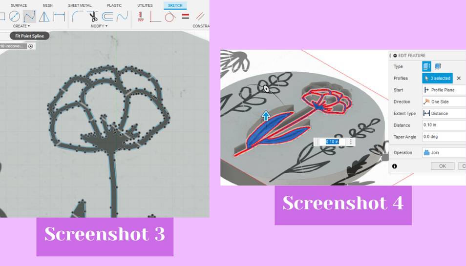
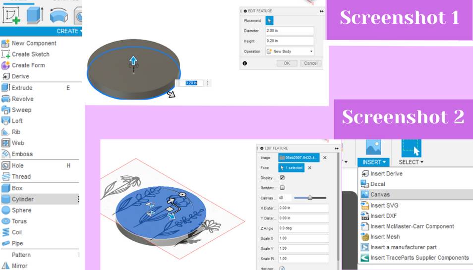 To trace the canvas I created a new sketch on the top surface of the cylinder. In the sketch workspace I used the fit point spline tool to go around the edges of the flower design to trace it (screenshot 3). Once I was done tracing the flower I hit the shortcut letter “e” to close and save the sketch and to open up the extrude dialog box (screenshot 4). In there I extruded my design up by 0.1 in.
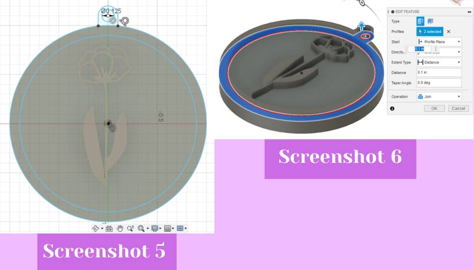
 From there I also felt like my design needed an outer edge so I created a sketch with two circles on the top face. One circle was the diameter of the existing cylinder and one was slightly smaller than that diameter (screenshot 5). Once I had these two circles, I hit the shortcut letter “e” and then I extruded the circle rim up to the same height as the flower which was 0.1 in (screenshot 6). From there I added a hole because it was originally supposed to be a keychain decoration but that didn’t end up working as you will see below (screenshot 5). To add this I created a sketch on the bottom plane of a center point circle that was tangent to the top edge of the design, I then added two lines from the side of the circle I sketched to the design. Next, I added a concentric center circle inside the circle I just sketched. Next, I clicked finish sketch and then hit shortcut letter “e” to extrude (screenshot 6). I extruded this sketch up to the same height of the rim and flower design, or 0.1 in heigh.
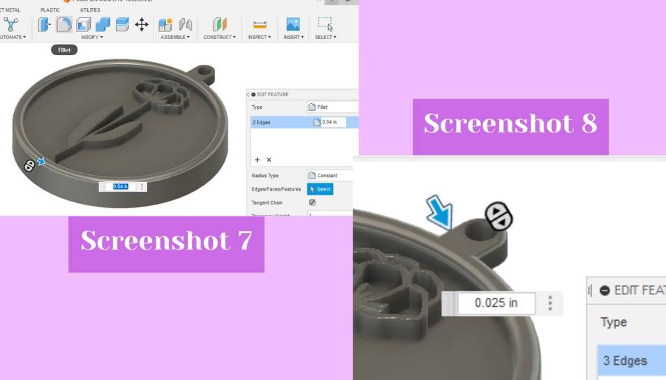
 Next, to add the fillet on the outer rim and bump out of the design, I clicked on the fillet tool from the modify menu (screenshot 7). I filleted the outer rim 0.04 in, and the bump out 0.025 in (screenshot 7 and 8).
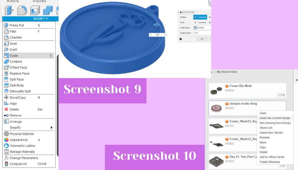
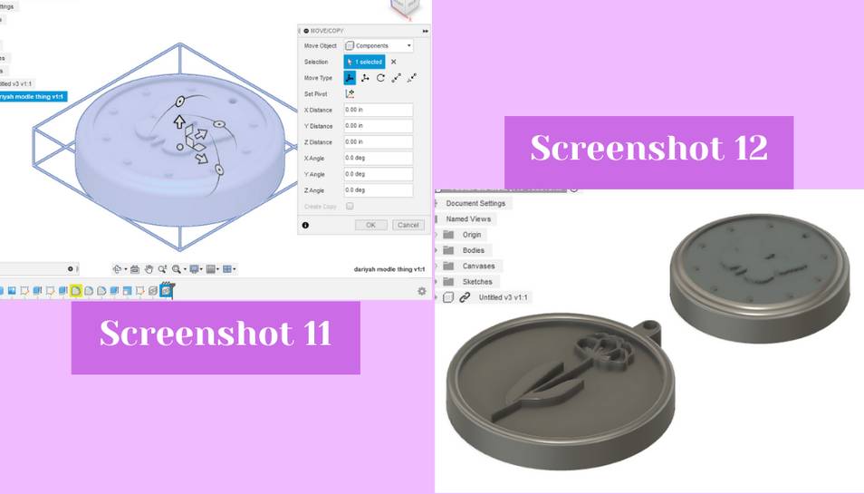
 Finally I thought my design was not big enough to make out some of the fine details of the flower so I decided to scale my design up, a trick I learned from Dariyah Strachan. To do this you go to the modify drop down in the 3D workspace, and then click on scale (screenshot 9). In the dialog box you select the object you would like to scale and then you can type a value for how much you would like to scale the design up or down in the scale factor box (screenshot 9). I scaled my design up 1.25. Finally, to make better use of the wax block and save time, Dariyah Strachan and I shared eachothers designs with one another so we could both add eachothers design to our design and then both generate a toolpath for it so that we could both learn how to do this skill. To add her design to my design, I had her export her design as a .f3d so that it would retain the correct fusion format and history. Once I downloaded it, I imported it into Fusion 360 by hitting the file button in the top left, then I hit the open button, next I clicked on the file, from there the design imported. To add it to my design file I clicked on the imported file, making sure the document I wanted was open in the background, and then I hit insert into current design (screenshot 10). This inserted her and my design into the same document (screenshots 11 and 12). With our design combined, I could then start on the toolpath.
Toolpath
It is worth noting that I have tried to use the Fusion 360 manufacture workspace before in my Engineering Designs Methods II class last spring, but I had a lot of trouble with it even with help from Dr. David Taylor and Mrs. Barbara Morrow, two former Fab Academy graduates and teachers. Our class, in small groups, was trying to make chocolate molds for Valentines Day by taking a Fusion design, using the manufacture workspace to make a toolpath, and then cutting the design from wax, to then make a mold from it. Dr. Taylor did end up working it out and tried to explain it to me, but I did not fully understand then what he did to make his work. Because of the trouble with the manufacture workspace, our class ended up abandoning the project, but going in with that prior knowledge was very helpful for this week.
To guide me, I followed Mrs. Barbara Morrow’s video on how to use the manufacture workspace because she had helpfully recorded a video for the 2023 Fab students on how to use the workspace.
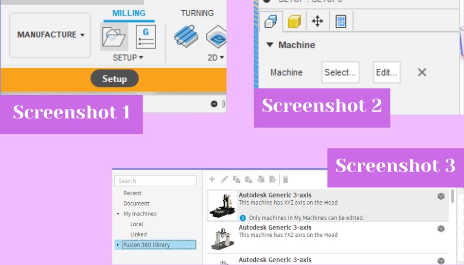
To begin in the manufacture workspace, I switched into the workspace by hitting the big box in the upper left corner and then clicking on “manufacture” (screenshot 1) This opens the manufacture workspace where the first step was to create a new setup. To do this I hit the file folder icon in the top bar on the left hand side (screenshot 1). This opened the setup dialog box where I could begin creating the setup for my material. The first step was to select a machine, and I chose the “Autodesk Generic 3-axis” by hitting “select” and then in the Fusion 360 library picking “Autodesk Generic 3-axis” (screenshot 2 and 3).
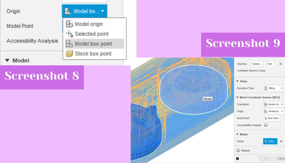
 Next I set the origin to the model box point by selecting that option from the drop down (screenshot 8). I could then pick a point of the model to set the origin at, and I chose a corner of the design. I then selected the two designs that I wanted to mill by using the model selector feature (screenshot 9).
 Next, I clicked on the second tab of the setup dialog box, this tab has a yellow cube at the top (screenshot 10). Inside this tab you can change the stock. I selected “fixed size box” from the mode drop down (screenshot 11), and then I entered the dimensions of the wax block Dariyah and I were using. We measured the block using a pair of calipers and then put those dimensions into our respective manufacture setups. I set the width as 3 inches, the depth as 8 inches, and the height as .63 inches (screenshots 12). Because Dariayh and I wanted to try a different way to make a two part mold, we decided to change the Z model position to “Offset from the bottom (-Z)” (screenshot 13). We did this so that we would mill out the object we designed and not a negative hole of the object we designed.
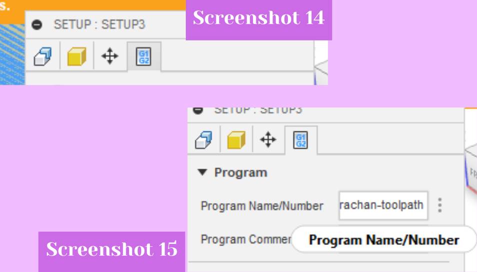
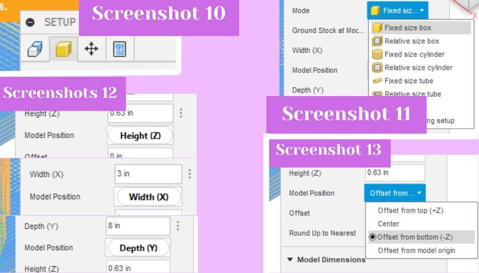 I did not change anything in the third tab of the setup dialog box, but I did change something in the fourth tab. The fourth tab has a white box with numbers on it and I clicked on it to edit the file name in the tab (screenshot 14). I typed in a file name in the “program name/number” to avoid confusion with other people’s milling files on the communal computer for the milling machines (screenshot 15).
 To confirm the setup I hit the ok button at the bottom of the dialog box. This created the setup and to see if it had worked you can look next to it in the left side browser to see if it has a green check. If it does not, something is likely missing, not updated correctly, or it has another problems.
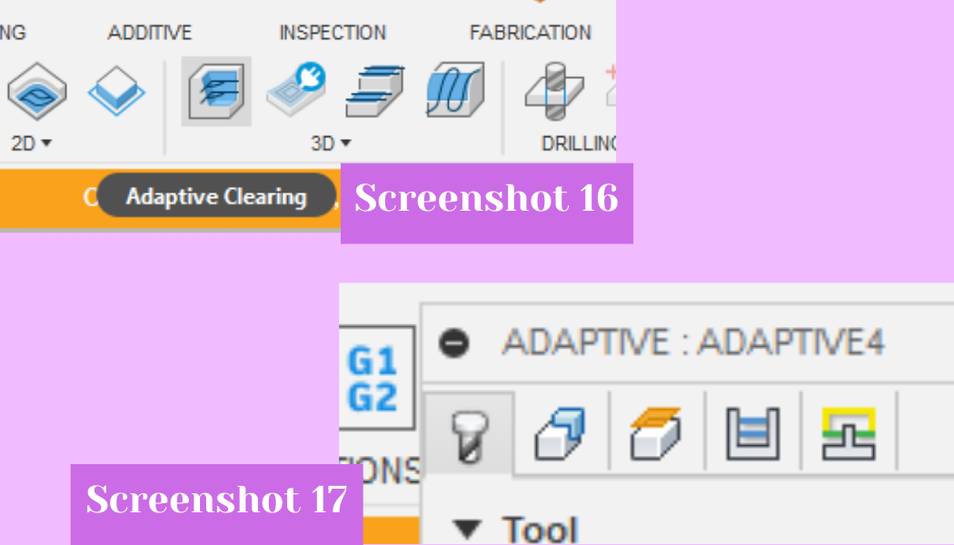
Next, I could create the toolpath after the setup was complete. To create a toolpath I went to the 3D tab dropdown and then clicked on the adaptive clearing option (screenshot 16). Inside the dialog box that opens and inside the first tab, the first step was to pick the tool that you would be milling with (screenshot 17).
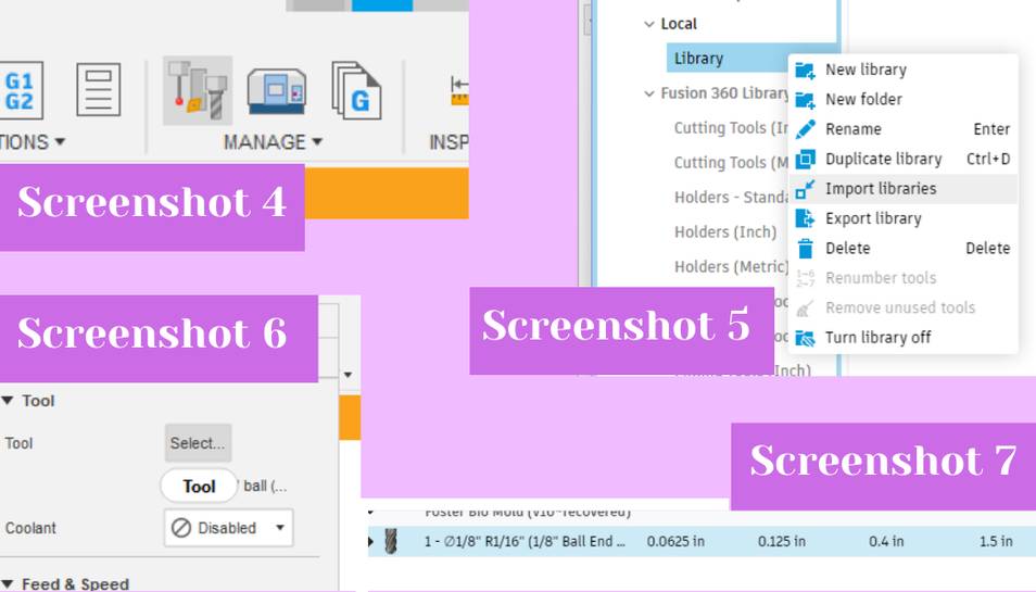
 I had to first download the Bantam Tools tool library because it had the tools that our lab uses frequently. To do this I searched online for “bantam tool library fusion 360” and the top hit was what I was looking for. I downloaded the file it linked, and then cliked on the tool library to open it up (screenshot 4). Inside the tool library I clicked on the local library tab, and then I right clicked on the local library tab to open up a menu of options (screenshot 5). From the menu I selected import library (screenshot 5). This opened up my downloads folder where I could select the tool library and add it to the Fusion tool library. With that the library was added and I could select a tool from that library for the adaptive clearing toolpath. To add that tool I hit the select button from the tool row (screenshot 6). I selected the 1/8” ball nose bit from the Bantam tool library becuase initally and incorrectly I misheard that that was the only bit we were allowed to use for milling wax (screenshot 7). Choosing this bit was sort of a big misstep by me because a ball nose bit uses only the very small end of the bit to remove material. The ball nose bit would have been better to use exclusively for a finishing pass, and some sort of two flute up cut bit would have been way better to use for an initial pass because it clears out a lot of material quickly which is the goal of a first pass. I only found this out after I had done the first pass using the 1/8” ball nose, but it was still a helpful learning experience because now I can use this information for future cuts.
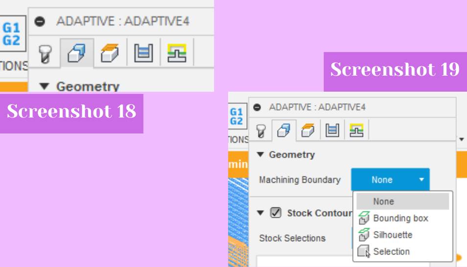
 With the tool chosen, I left the feeds and speeds as the presets and moved onto the second tab of the adaptive clearing dialog box. The second tab has a white and blue cube and I clicked on that to open it up (screenshot 18). Inside there I set the machining boundary to none from the drop down because I wanted basically all of the wax block gone except for my design (screenshot 19).
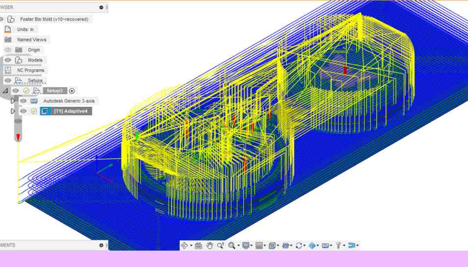
 I left the third, fourth, and fifth tabs alone for my initial pass, and clicked ok to generate the toolpath. Once the toolpath was finished, I let it generate which took ~2 minutes. I could then see the tools’s proposed route.
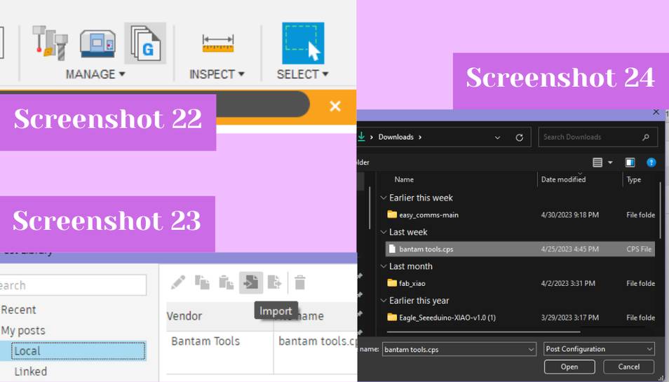
 With everything looking okay, I then could export the GCODE. To do this I had to download a special post processor and I learned this from fellow Fab 23’ student Merritt Backerman. To do this I googled for Bantam Tools Fusion 360 post processor, with this website being where I found the post processor. I downloaded the post processor from that website and then navigated to the post library from the manage tab inside Fusion (screenshot 22). Next, I clicked on the file icon with a right pointing arrow which is the import button (screenshot 23). I selected the post processor file from my downloads and then the library was imported (screenshot 24).
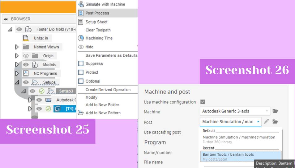
 To use the post processor once it was installed, I right clicked on the adaptive clearing toolpath in the browser (screenshot 25). Next, I chose post process from the list of options (screenshot 25). It then opened up a window where I could name the file and choose a post processor. It automatically selects machine simulation but if you click on the file icon on the right of the post line, you can pick your own. I chose the Bantam Tools one because it was what I needed (screenshot 26). From there I could change the file name and then to generate the toolpath I hit the post button. With that I had generated the initial toolpath.
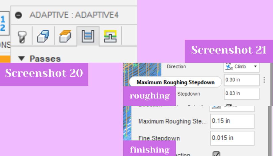
 To generate the finishing toolpath, I learned from Dr. Taylor that I could chnage the stepover of the toolpath to make it tighter and get a finishing toolpath that way. After learning that, and while milling out the inital toolpath I went and made the finishing toolpath. I right clicked on the adaptive clearing toolpath and then hit the top edit button to change the toolpath’s settings. I searched in all of the five tabs for somewhere to change the stepover, but all I could find was the stepdown. I also tried googling to see if someone else knew where I could find it, but I also could not find any advice on the location of the stepover. I read the discription of the stepdown and decided that it was very similar to what I wanted, so I chose to edit that for my finishing pass. I decided to half the stepdown value from .3 inches to .15 inches (screenshot 21). The stepdown can be found in the fourth tab of the dialog box which has a white U with two blue lines in the middle of it (screenshot 20). With that changed I exported the GCODE again using the same method as above.
Milling
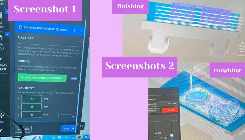
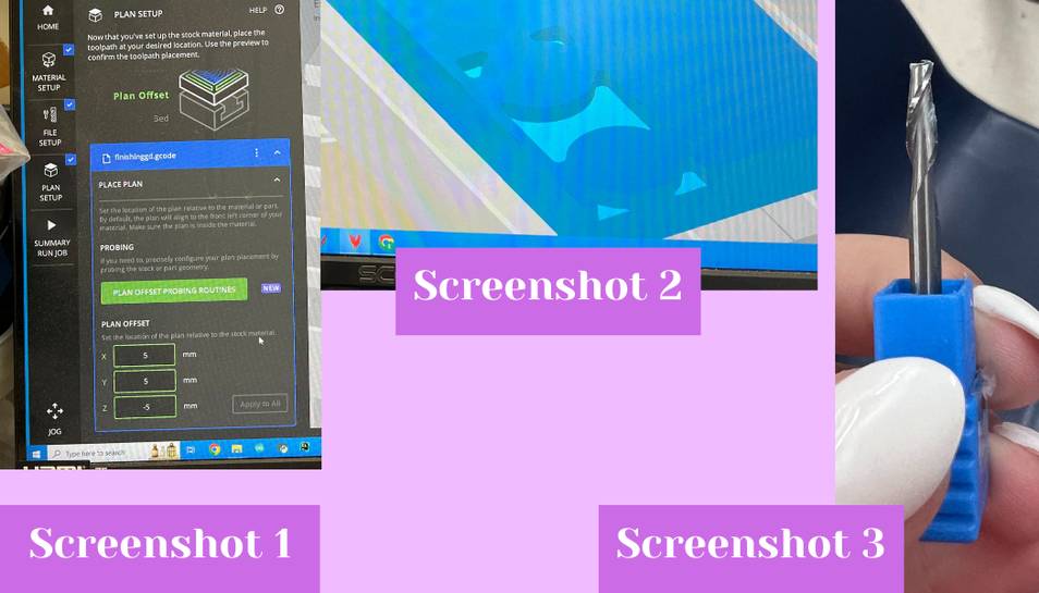
To mill our designs, Dariyah and I picked one of our files to mill and then went to the large milling machine in our lab. The large milling machine is a Bantam Tools Desktop CNC Milling Machine. We first used Nitto tape to secure down the wax bocks to the machine bed. We went through the Bantam milling software to upload and mill the file. The software is incredibly easy to use and to get started, we uploaded the GCODE file by clicking on the import design button in the file setup tab (S1). Next, we selected the tool we wanted to use with was the 1/8” ball nose bit which was already added in the machine from a previous person using it to mill (S1). We originally thought this was the only bit we were allowed to use, but we later found out that we could use virtually any bit that goes in the mill for the wax because it is hard wax, you will also see more on that later. From there we could change the material size in the material setup tab (S3). We added the measurements of the wax block to the corresponding measurement boxes (S3). Next, in the plan setup tab we could edit the position of the toolpath in relation to the material (screenshot 1 and S2). We changed the position of the tool path to be 5.5 mm from the X axis, 25 mm from the Y axis, and -39 mm from the Z axis (screenshot 1 and S2). The the axis was set about .1” from the bed because we did not want to hit the bed as another Fab Academy student accidentally did. With that set, we went to the summary job tab to mill the file by clicking mill single file (screenshot 2). Once it starts milling you can also adjust the feed and speed from the default 100% that it uses for milling by using the feed rate and spindle sliders. We ended up using ~50% feed and ~120% spindle after some advice from Mr. Adam Durrett which I mention below.

 The machine started the spindle and it started carving out our design (screenshot 3). Periodically, Dariyah and I had to pause the mill to use a vacuum to suck all of the wax flakes off the top of the material to prevent the bit collet from getting gunked up with wax. We did this by hitting the pause job button and then by opening the safety cover after the mill had paused and using the vacuum to suction everything out. We could then un-pause the mill and it would (usually) start up again fine. On our first mill, about 1/6th of the way in, the wax block suddenly pulled up from the machine bed while the bit was moving through the machine (screenshot 4). Because I very quickly hit the red emergency stop button, the bit did not break, but we did have to restart the entire toolpath mill again because the emergency stop resets the machine.
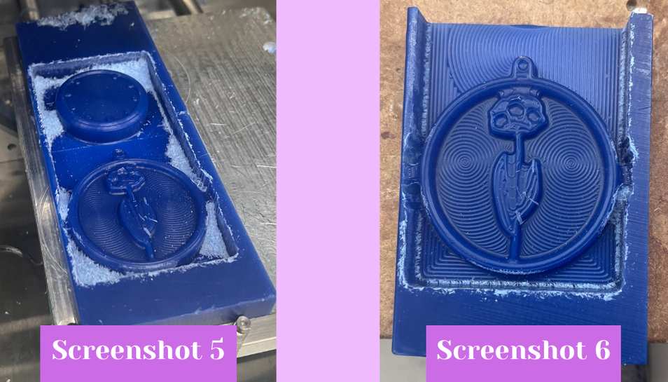
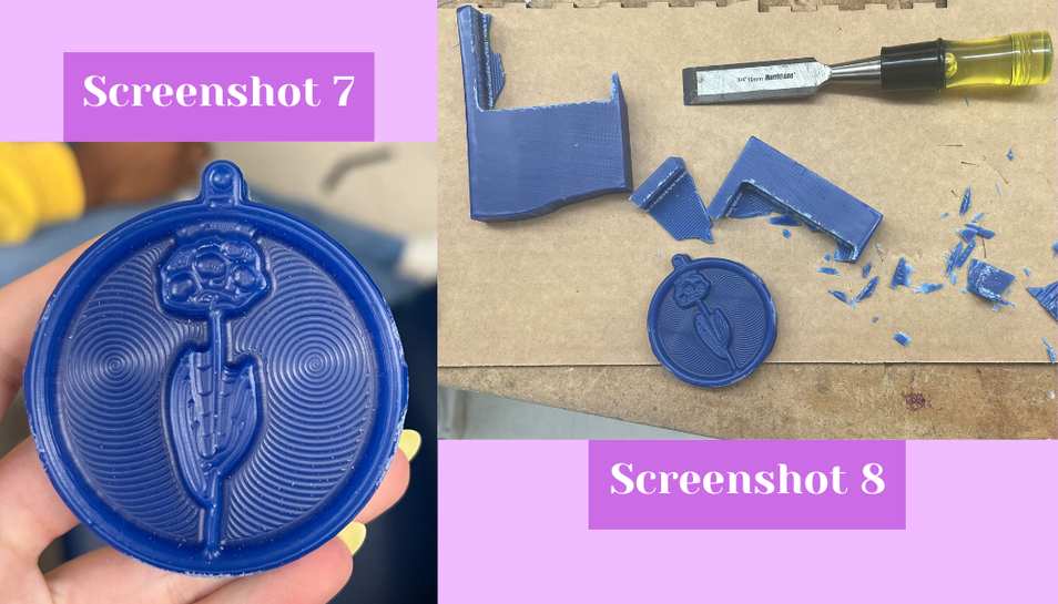
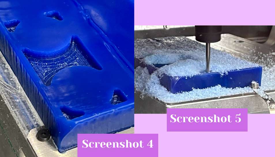
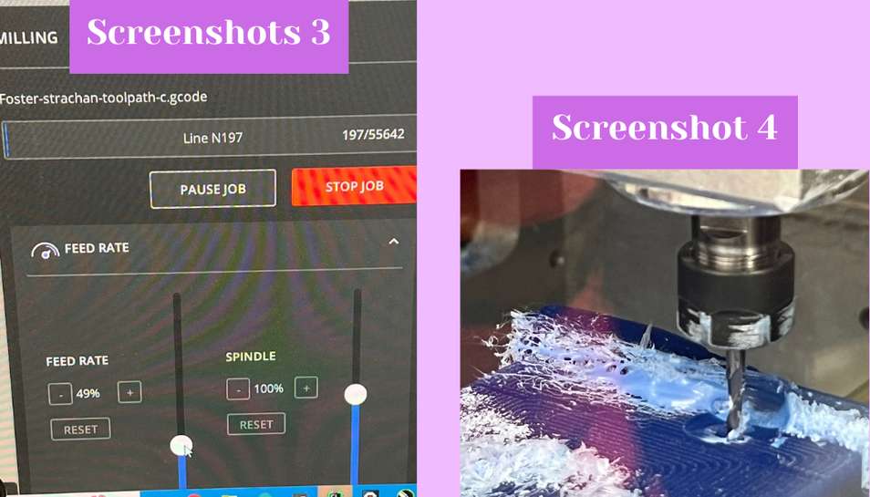 We took this opportunity to bandsaw the wax blocks about half way down. We learned that the wax block has to be very well secured onto the bed, so when we reattached it, I first took some 80 grit sandpaper to the bottom of the wax block to rough the bottom to allow for a better adhesion between the Nitto tape and the wax block. We reattached the wax, changed the plan setup offset to -14 mm and then restarted the mill. This time, everything was going well with the vacuuming until about 4/5ths of the way in, after vacuuming out the wax shavings, the job would not un-pause and start again. Because of the refusal to un-pause the job, we were left no choice but end the job and start all over again. This was really annoying, and we were warned that it sometimes happens, but we also needed to remove the wax shavings so it was pretty much an unavoidable problem. After restarting it, we had to wait for it to air cut until it could get back down to the unfinished areas. We also then got a tip from Mr. Adam Durrett that to stop the very high picthed whiny-screechy sound that the mill makes while milling the wax we could change the feed rate to 50% and the spindle speed to ~120% from the milling box inside the bantam software (screenshot 3, seen above). This helped with the noise significantly. After the third try worked and went all the way down, we could then run the finishing toolpath. We followed the same uploading process as we did above, and then set it to mill. This mill also ended up refusing to unpause about 1/2 way through so it had to be run twice to get it to fully mill. Once the mill was done, we used a paint spackle knife to pry the wax off the machine bed (screenshot 5 and 6). We then used a chisle and a wooden mallet to chisle the piece the rest of the way off the wax block (screenshot 7 and 8). Then we could proceed to molding our pieces.
Milling pt. 2
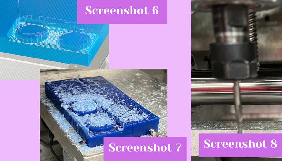
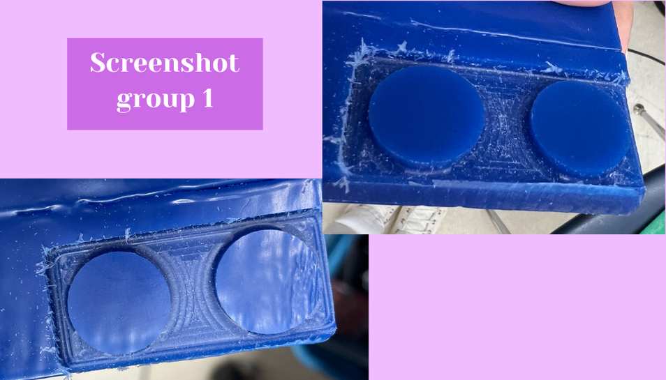
I later went back and milled a second piece of wax to demonstrate that I know how to a roughing and finishing pass. Because Dariyah and I had done our wax together we also did this together so we both individually made the tool paths which was of two 1” circle with a .2” height. We made a pocket toolpath for a 1/8” two fluted up-cut flat endmill the roughing toolpath because it would clear out a lot of the empty space in the design and leave the smaller detail for the finishing toolpath. For the finishing toolpath we both used the adaptive clearing option and set it for the 1/8” ball nose end mill. I exported both toolpaths as G-CODE and then went to the milling machines. I opened up the roughing file inside the bantam milling workspace inside the file setup tab. In the file setup I offset the toolpath in the X by 5 mm, in the Y by 5 mm, and in the Z by -5 mm (screenshot 1). The toolpath looked right in the viewer so I then added the bit (screenshot 2).I added the 1/8” two fluted up-cut flat endmill to the large bantam milling machine (screenshot 3).
 I then hit the mill single file button and the machine began the roughing pass (screenshot 4 and 5).
 After it was done, I uploaded the finishing pass file into the milling workspace (screenshot 6) and I also changed the bit to a 1/8” ball nose end mill (screenshot 8). I hit mill single file again and the milling machine ran the finishing pass (screenshot 7).
 The combination of the two left me with a nice looking cut (screenshot group 1).
- Milling pt. 2 roughing and finishing toolpath file .f3d
- Milling pt. 2 roughing and finishing toolpath file .stl
- Milling pt. 2 roughing file G-CODE
- Milling pt. 2 finishing toolpath file G-CODE
Molding The Piece
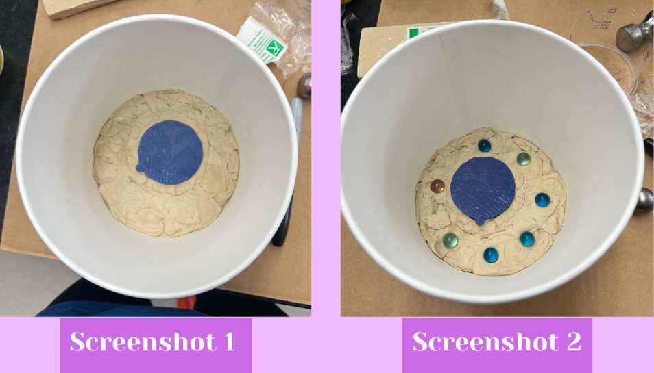
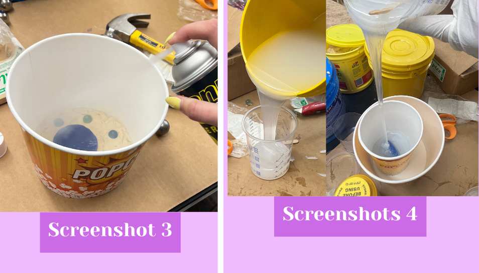
To make a mold of my piece I followed the instruction from this video by the company, Smooth-On, that makes MoldStar, Task8, and other popular casting and molding products. Before starting I also reviewed the MoldStar 31T datasheet from here. This video basically says to place your desired object half in clay inside a molding box (screenshot 1). Then add acorn nuts to the clay, spray two coats of mold release, and pour MoldStar over the exposed half of the model (screenshots 2, 3, and 4).
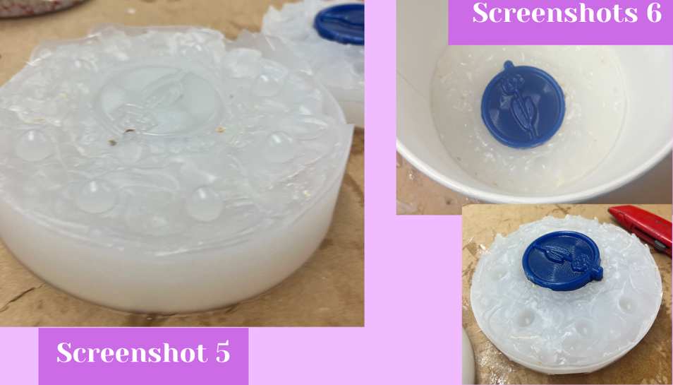
 From there you let it set up and then demold the clay and acorn nuts from that half while keeping the model embedded in the silicone half. You then reassemble the mold box around the model embedded in the silicone (top photo screenshot 6). Once it is reassembled, you spray two coats of mold release on the top surface of the model and silicone to prevent the other half of the mold from sticking it to it. From there you add a cone shaped piece of clay off the top so you can pour in whatever casting material you want once the mold is done. Then you can pour a second layer of MoldStar on to make the second half of the two part mold. Once it is set you remove the mold box and separate the two layers (screenshot 5).
 With that you have a two part mold. I essentially also followed these steps, but instead of a mold box I used a paper popcorn bucket because our lab uses those for molding. I also used marbles instead acorn nuts because Dariyah and I could find those more easily.
Casting From My Mold
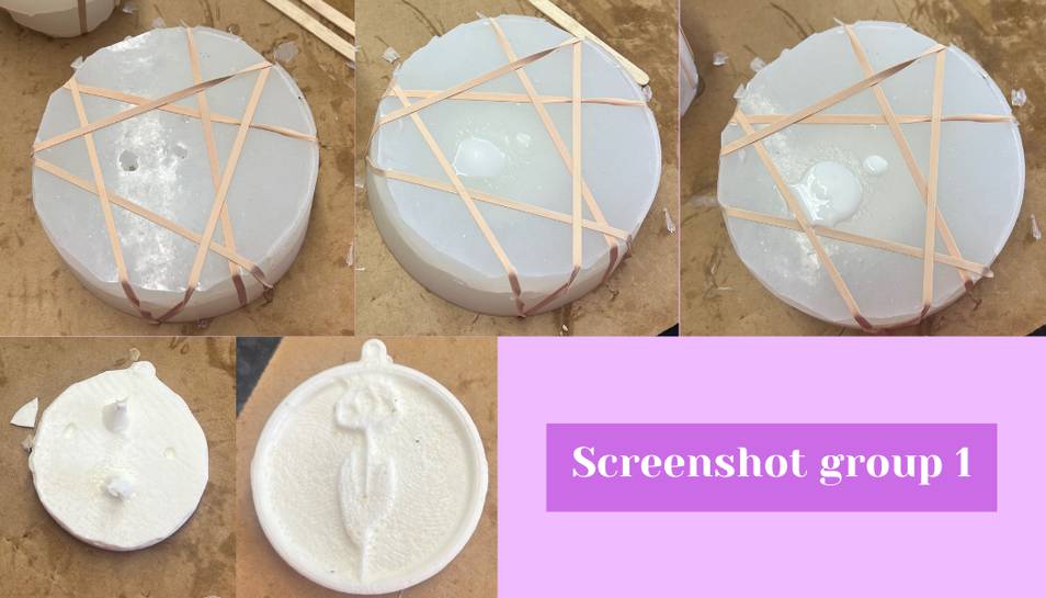
To cast using my two part mold, I began by realizing that I had forgotten to add a pour spout and a vent to my mold so I had to use an Exacto knife to carve out a hole in the thinnest part of the top of my mold. I took the knife, made an X cut and then cut the triangles to create a vaguely circular pour and vent holes. To ensure that the casting material would not stick to the mold I took mold release and sprayed it generously all over each mold half. Next, I placed the two mold halves together and then I took ~5 rubber bands to secure the two mold halves together (first photo screenshot group 1). Before mixing the TASK-8, I reviewed the datasheet from here and made note of the fact that the TASK-8 gets very hot when the two parts are combined. From there, I mixed in a 1:1 ratio parts A and B of TASK-8 using plastic cups and I popsickle stick. From there I quickly mixed the two parts because the pot life is 2.5 minutes. After I thought it was satisfactorily mixed I poured it through the pour spout and into the mold. After it was poured in I left it to set up (second and third photo screenshot group 1). I came back later and began removing the rubber bands to demold the cast. I took off the top of the mold, but because the TASK-8 expanded up a bit after I left it, there was a spout in the bottom that prevented immediate demolding. I broke up this spout up by using a chisle and a wooden mallet (first photo second row screenshot group 1). I hit the TASK-8 spout several times with the chisle until it gradually broke off in serveal pieces. I eventually broke it back the the mold and could then demold it. (last photo second row screenshot group 1)
Concluding Thoughts
This week I learned basically the entire process of how to make a mold and cast it. Through that I finally learned how to actually use the Fusion 360 manufacture workspace for milling, though I do personally find it still a little hard to work with as it is, in my opinion, not that intuitive. I also came to learn that you should ideally use the biggest bit possible for a roughing pass, and a smaller bit like a ball nose bit for a finishing pass. I also learned that I should remember to put a pour spout and a vent in my two part mold because without it you cannot pour material in and you will have to DIY a messy one, like I did, with a knife. Furthermore, I learned that when mixing the two parts of TASK-8, I should probably mix a little more slowly to prevent air bubbles in my cast. Finally, it did not effect any of the molding process, but I probably should have tried to smooth out the clay a little bit more so that two halves of the mold would fit together more seamlessly.