3. Computer Controlled Cutting
This week I participated in the group project assignment to test our laser cutters, made a vinyl sticker, and made a laser cut parametric design.
Group Work
We characterized the settings of our laser cutter. You can see my work along with Dariyah Strachan, Dylan Ferro, Stuart Christhilf, and David Tian on theCharlotte Latin Fab Lab site for student group B. This week I learned that color mapping very finnicky on the medium laser cutter and that if you need to color map for a laser cutting design you should use the large laser cutter because you can split the design by color in the printer settings window and you don’t have to manually enter the colors which removes a possible point of error. I also learned that you can switch color palettes in CorelDraw because our color palette was in CMYK which caused everything to mess up and one of our teachers, and fellow Fab Academy participants Mr. Zack Budzichowski told use after we had already switched laser cutters that you could switch the color palette from CMYK to RGB.
Vinyl Sticker
To begin this week I decided to make my vinyl sticker. Because at the Charlotte Latin Fab Lab, we stick our stickers on the window of our teacher’s office, I knew I wanted the same design for the sticker that’s on the back of my laptop, because it is a lyric from one of my favorite songs by my current favorite band that should definitely be immortalized on Charlotte Latin School property for forever. The song is Snap Out of It by the Arctic Monkeys, and I found the sticker online at this link.
Creation of My Sticker Design
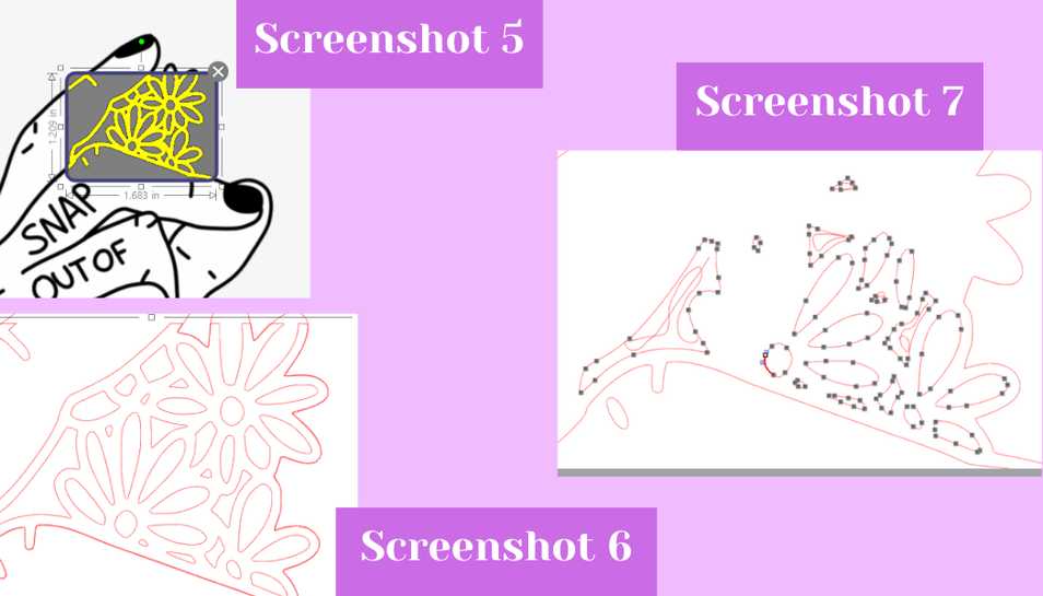
I started by clicking file and then pen and opened the file that my sticker reference image was in. After opening it, I didn’t bother resizing it yet and instead clicked the butterfly looking symbol in the right hand side bar to open the trace panel. After opening the trace panel I clicked on the top ‘select trace area’ button and dragged over the main design in the image I imported. After selecting that, I toggled around with the sliders and buttons in the trace panel until I liked the yellow outline that was displayed (screenshot 1). When I was done I clicked ‘trace’ under the trace styles menu to trace the image. It then generated a red outline of my sticker which would be what I would cut from black to create the outline (screenshot 2).
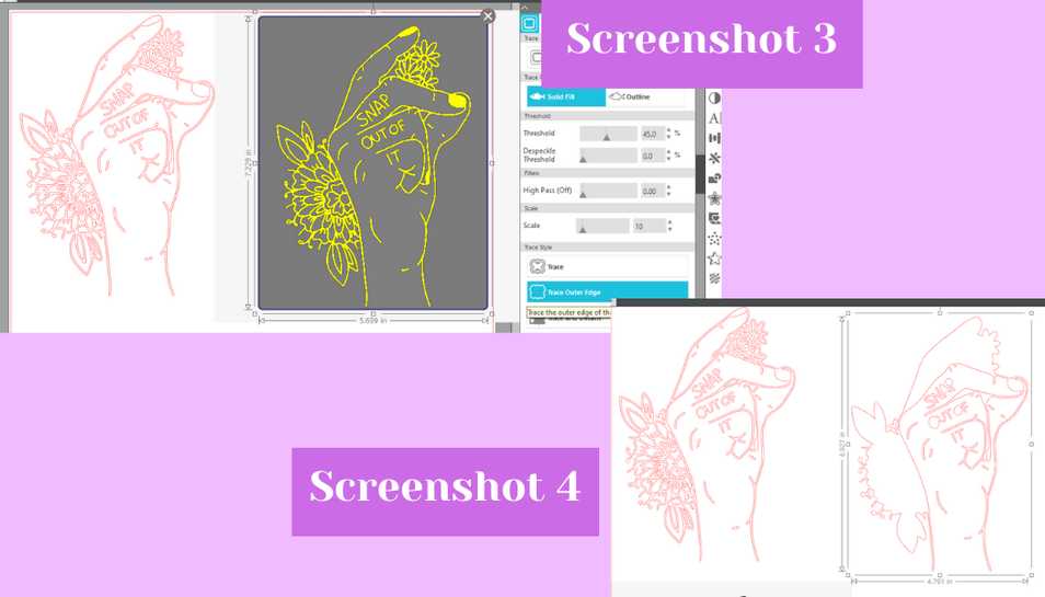
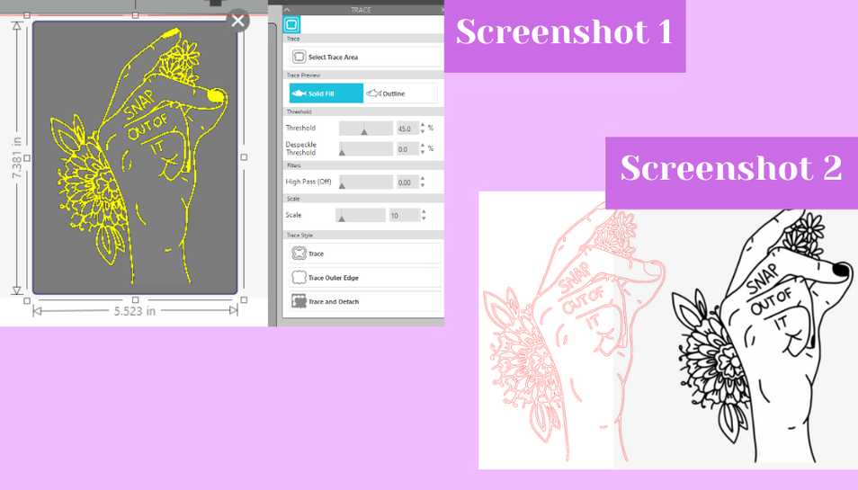 Next I traced over the reference image again but this time I clicked ‘trace outer edge’ from the trace styles menu (screenshot 3). While this did trace the outside edge I also found that it did trace some of the inside too (screenshot 4).
 To fix this I double clicked on the inside red lines and selected with my cursor one of the red lines so that it became highlighted. Then I began repetitively hitting the delete key on my keyboard to begin removing the unwanted inside red lines (shown in screenshots 6 and 7 with smaller parts of my design). I went through and did this until the only lines left were just the outermost red lines but I did keep the lines where there was negative space in the main part of the image like the gap between the first and middle finger. I did this because this part of the sticker would be the white background for the rest of the sticker and couldn’t have any gaps except for there was negative space. Next, I began tracing smaller sections of the image to create the cut lines for the more detailed parts of the sticker that I wanted to be in a different color other than white or black (screenshot 5). I did this for both flower clusters, the leaves, and the center of the flowers. With the smaller traces I also went through the process of double clicking on the red lines, and then using the select tool to click on a line and then using the delete key to delete the unnecessary lines (screenshots 6 and 7). You can download the file below.
My Vinyl Sticker File Download Studio3
My Vinyl Sticker File Download .svg
Vinyl Cutting My Sticker
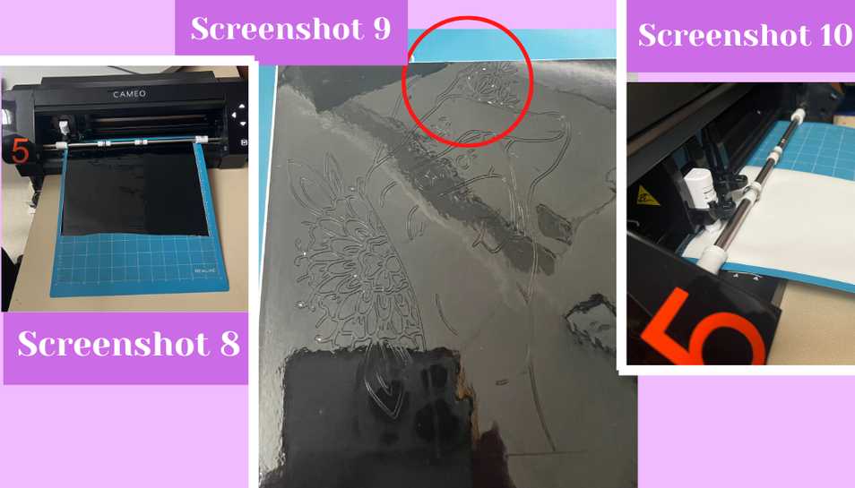
Once I had the cut lines for the black outline, the white background, the two flower clusters, the leaves, and the center of the flowers I went to find my vinyl. I chose shiny vinyl for all of the parts of the sticker, and I went with black for the outline, white for the background, two different shades of green for the leaves, deep yellow for the center of the flowers, and a lilac purple for the flower petals. With my vinyl chosen, I used the Cameo 5 vinyl cutter to cut my stickers. I started the cutting process by sticking down a piece of vinyl to a sticky cut mat which I then loaded by pressing the up arrow on the right screen of the Cameo. With the cut mat loaded, I removed all of the red design lines from the workspace by dragging them out except for the one that I needed to cut. With only the design I need on the workspace, I switched tabs in Silhouette Studio from the design tab to the send tab located in the top right corner of the page. In the send tab I changed the material from the drop down tab to ‘Glossy Vinyl’ from there I just hit the send button at the bottom of the send tab to send my design to the vinyl cutter. On the vinyl cutter, I hit the play button on the right side screen and my design started cutting (screenshot 8). I did this for all of my colors of vinyl and only had an issue with the black vinyl (screenshots 9 and 10). For the black vinyl I accidentally sent the design to cut too far up on the page causing the vinyl cutter to cut off the piece of vinyl creating an incomplete sticker design (screenshot 9). To fix this I had to move the red line design further down on the design page and then re-cut on the vinyl. The second time it came out much better.
Assembling My Sticker
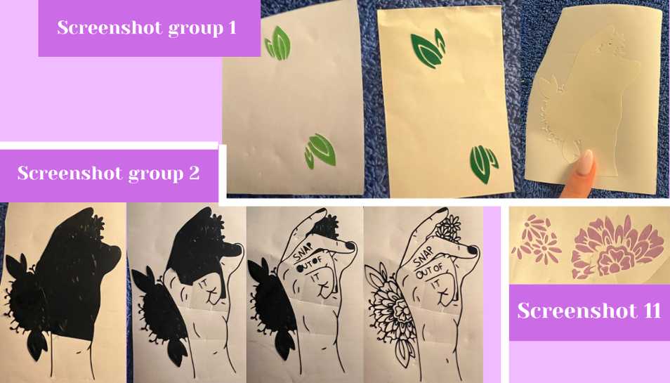
To assemble my sticker was slightly challenging and time consuming because I went slowly to make sure everything came out looking good. I began by peeling off all of the background vinyl not used in my design (screenshot group 1). Next, I started doing the same for the black outline sticker. Because this sticker had many thin and small disconnected lines I decided to take a knife and cut the vinyl to work in sections. Going section by section, I used three different pairs of tweezers to carefully weed the vinyl (screenshot group 2). Eventually I got all of the black vinyl weeded, only loosing one tiny thumb crease mark which was so small it was not worth replacing. Then I worked on weeding the flower clusters which was far harder than the black outline because it was difficult to work in sections because of the many tiny petals of the flowers (screenshot 11).
 Next I began carefully assembling my sticker. I used some clear transfer tape to stick my sticker on top of one another, and I started by putting any petals that had come off of the sticker paper while weeding onto the black outline sticker because that’s where they would have ended up if they had not accidentally come off the sticker paper. Only a few pieces needed this like some of the flower petals and the yellow insides of the flowers. Then I used the transfer tape and stuck it overtop of the black outline sticker. Next I used the edge of my credit card to make sure the black vinyl fully adhered to the transfer tape. After making sure it was pressed down well, I carefully and slowly peeled the white sticker backing off from the sticker. This left the black sticker outline, sticky side out, adhered to the transfer tape (screenshot group 3 picture 2). I then placed the white background flat on my desk and slowly lined the black outline up with white background. When I felt confident that it would stick on straight and in line with the white background I laid and then pressed the transfer tape down onto the white background sticker. I then used my credit card again to press down on the transfer tape to make sure that the black sticker was fully stuck onto the white sticker (screenshot group 3 picture 3). When I felt sure that everything would stick, I peeled back the transfer tape revealing my black outline overtop the white background (screenshot group 3 picture 4).
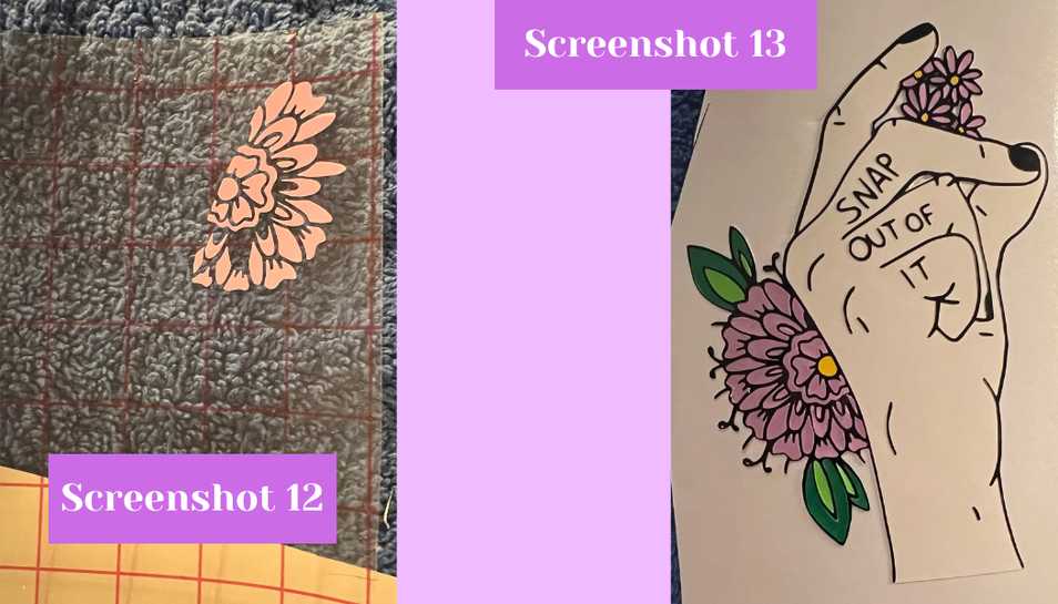
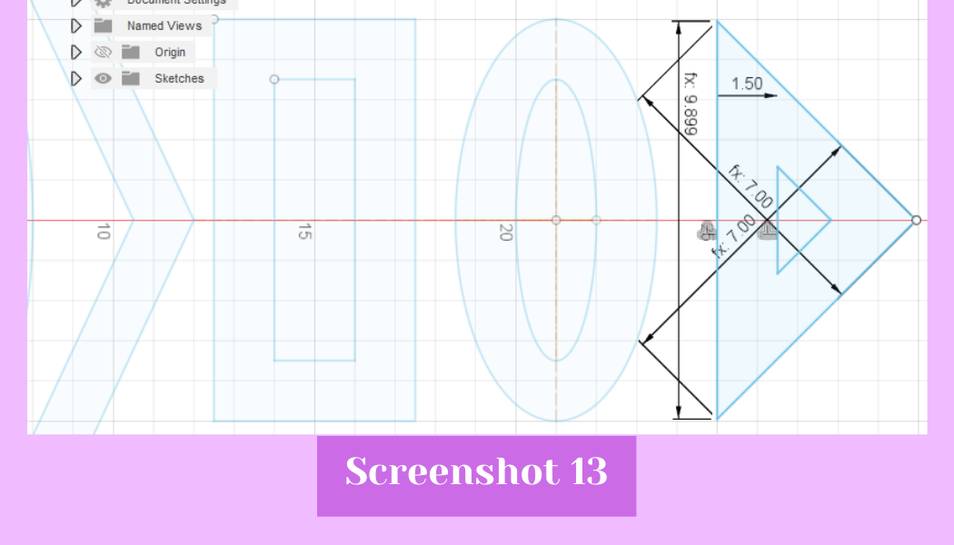
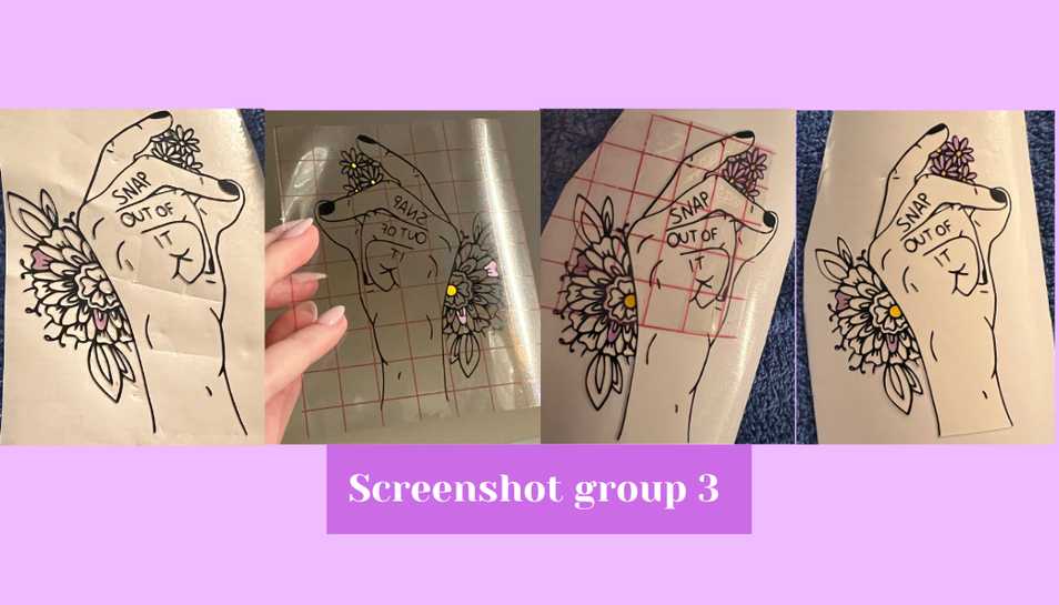 I then used more transfer tape and repeated the same process of sticking it to the front of the stickers needing to be moved, peeling the backing off, and then aligning and sticking the sticker down on the white background with the black outline. I did this for the petals, and the leaves (screenshot 12). For the leaves I decided which green I wanted on the outside and which green I wanted on the inside, and then removed the corresponding leaf part from each cluster. Once I had everything stuck down, I had finished and the only thing left to do was use transfer tape to stick my sticker to Mr. Dubick and Dr. Taylor’s office window as is tradition with the Charlotte Latin Fab Academy students (screenshot 13).
Parametric Design
I began to make my parametric design by finding something cool I wanted to design. I googled parametric design and scrolled through the images until I found something I wanted to design. The inspiration was for a parametric lampshade, but I just liked the shape of it so did not make the hole for lamp, but someone could always add a hole for the light to go in if wanted. The link for the inspiration image can be found here. Though the link is for a tutorial on how to make the lampshade, I did not watch or follow the tutorial. I decided to design in Fusion 360 because it is where I best know how to use user parameters.
Designing in Fusion 360
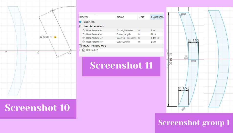
To start designing I went to the modify tab drop down and clicked on the change user parameters button to open the user parameters box where they can be added and edited. I added a parameter for four things initially. One for material thickness, one for circle diameter, one for curve length, and one for curve width (screenshot 11). With all of those added I clicked ok and then clicked the create a sketch button from the top bar. I selected the XY plane as the plane for the sketch. Once in the sketch menu I created a circle by selecting the shape from the top bar. I used the origin as the center point of the circle and in the box that opened up where you can type a number to change the diameter of the circle, I instead typed the text for the user parameter I set: “circle-diameter.” After entering that I created a second reference circle just to keep my tabs aligned correctly. The second circle was 1.5” less than the circle-diameter. Next I created a reference line by using shortcut letter “L.” The line was a horizontal radius coming from the center of the circle. Then I used the line tool again by the shortcut to create a rectangle using the user parameters “material-thickness” for the width, and “curve-width” for the length (screenshot 1). Then I used the trim tool from the top bar (scissors icon) to remove the part of the rectangle which touched the outer part of the circle and the bit of the circle between the two long lines. Doing this created a slot in which the pieces could fit into. Then I before I copied this around the circle, I created some more guidelines. I made three lines using the line shortcut letter “L” from the center, each 22.5° degrees away from one another so that each slot would be an equal distance from the others. With those lines turned into construction lines in the sketch palette on the right, I could copy and paste the first slot around the circle. I started doing this by selecting the three slot lines and copying and pasting them using the ‘command’ key and ‘C’ and then the ‘command’ key and ‘V’ (screenshot 2). Once it copied, I used the arrows and circle slider that appeared to move the slot around. I used the circle slider to tilt the slot to an angle of 22.5° and then the up and right arrows to position the slot so that it touched the edges of the inside and outside circle (screenshot 3).
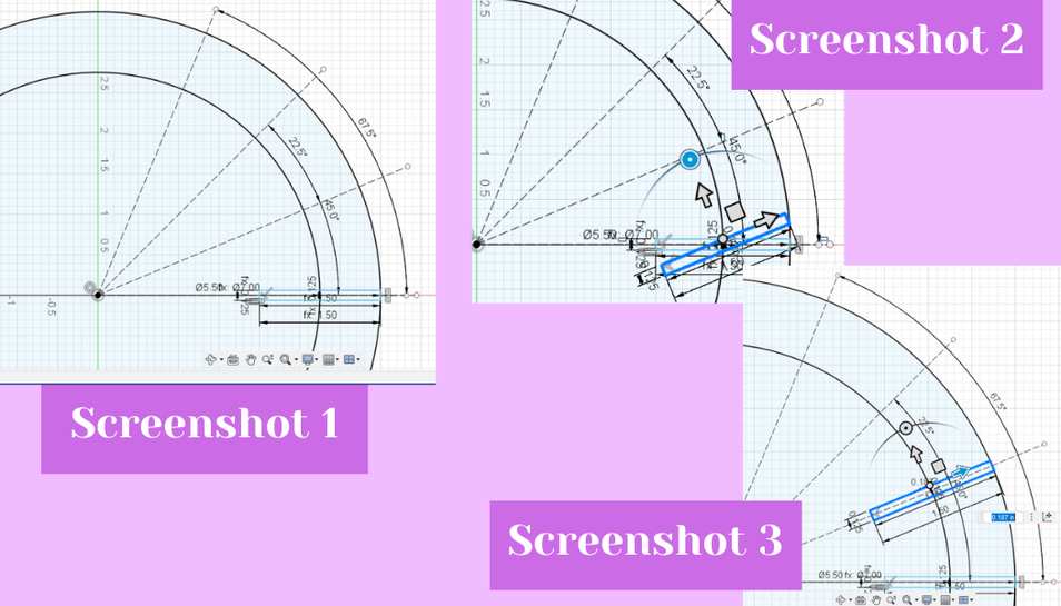 Then I used the trim tool from the top bar to remove the part of the outside circle that the slot lines intersected with. I repeated the copy, paste, rotate, move, and trim process for the slots at 45° (screenshot 4), 67.5°, and at 90° (screenshot 5).
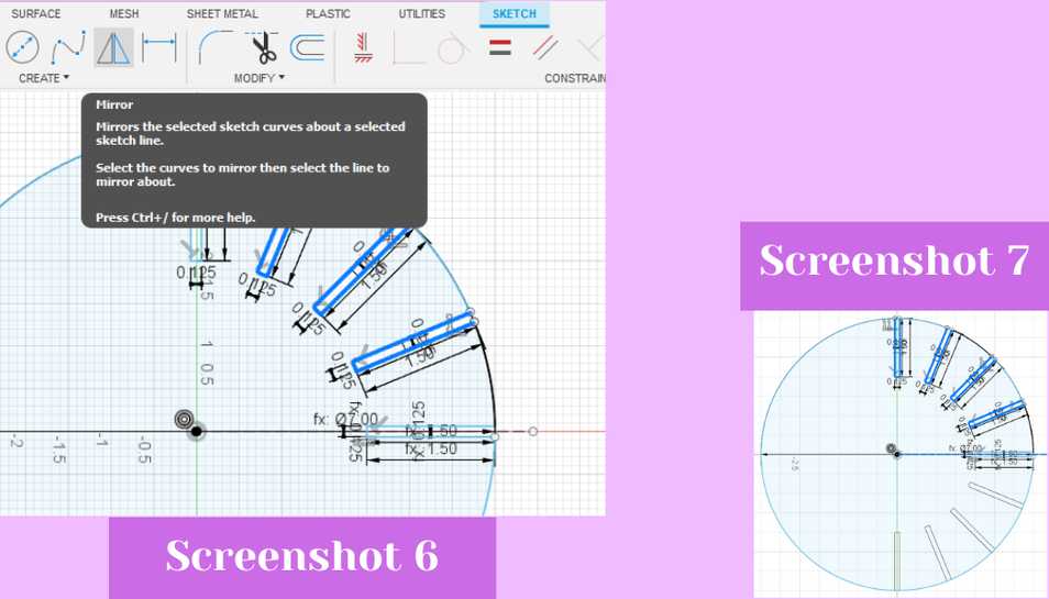
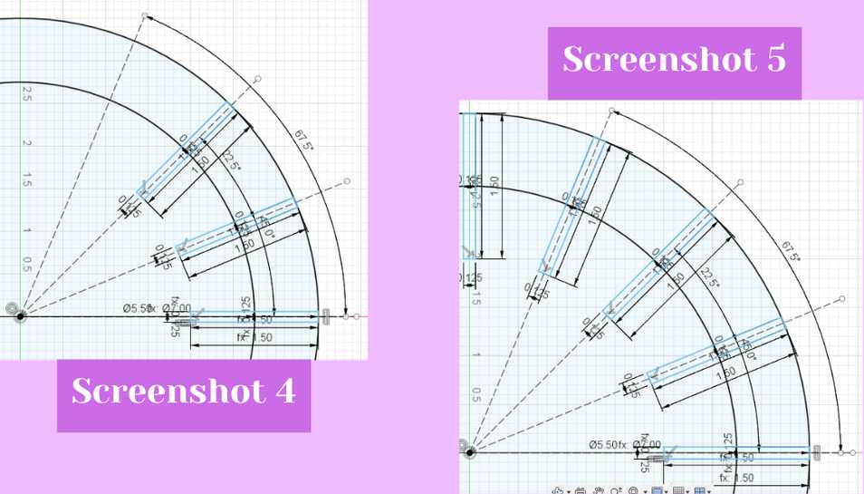 Once I had all of the slots for the upper right corner I used the mirror tool to mirror the slots from the top to the bottom right (screenshot 6). In the mirror dialog box that opened once I selected it from the top bar, I selected all of the slot lines except that horizontal slot as the objects to mirror and the mirror line as the horizontal guideline (screenshot 7).
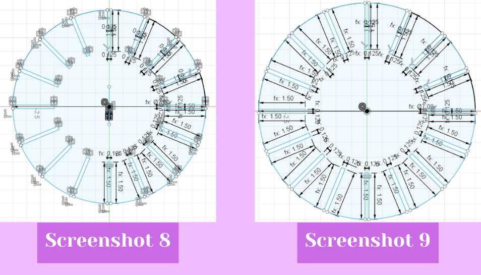
 When they mirrored, I used the trim tool to trim the parts of the outer circle which intersected with the slot lines. Then I dimensioned every line with its corresponding user parameter to make sure that if the user parameters were changed that the mirrored slots would also change. From there I mirrored all slots except the verticals slots to the left side of the circle (screenshot 8), again trimming the outer circle, and dimensioning the lines with user parameters (screenshot 9).
 From there I created more user parameters for the arc, the elongated >, the rectangle, the oval, and the triangle (screenshot 10 and groups 1 and 2).
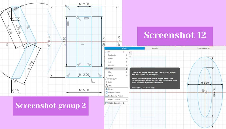 I then used the line tool and inputting the user parameters for the creation of all shapes except the oval. For the oval I used the elipse tool from the shapes drop down menu to create it (screenshot 12, see above). I used user parameters for all of these to ensure they were the same width and could also be changed if I so desire. After creating all the shapes I went to laser cut them out (screenshot 13). You can download my parametric file below.
Kerf
One thing I had to consider while designing was how to incorporate the laser cutter kerf into my design to ensure that my design would press fit correctly. Kerf is the small (yet substantial) amount of material that gets vaporized by the laser while cutting. If kerf is not taken into account, for example a 3” diameter circle will measure in at 2.9” if the kerf is 0.05”. To make that circle 3” exactly you would have to design the circle to be 3.1”. You can find a more detailed explanation of kerf here. Anyways, to account for the kerf of my lab’s laser cutters, I set the parameters to account for the kerf on the main wheel’s slots by adding 0.02” (the laser cutter’s kerf) to each user parameter I set. I did mess up slightly because the first time I went to cut, I subtracted the kerf value instead of adding it, resulting in too tight of a fit, and the second time I overcorrected resulting in a loose fit, but the third time I hit the nail on the head by adding .02” like I should’ve originally.
My Parametric .dxf File Download
My Parametric .f3d File Download
Laser Cutting Parametric Design
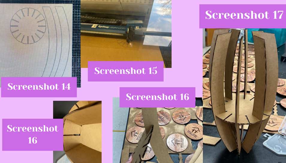
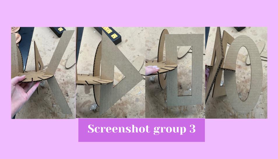
I began by exporting my Fusion 360 design as a .dxf and then uploading my design to the large laser cutter computer. Then I made sure that all lines were hairline and hit print. In the epilog print screen that opened, I imported the settings to cut or vector cardboard, and then loaded my material into the bed of the laser cutter. The print setting for vectoring/cutting cardboard are preloaded, as the lab has pre-set options, but the speed, power, and frequency were set at 40.0%, 100.0%, and 10.0% respectively. Then I made sure auto focus was selected, dragged the design overtop of the cardboard, and then hit print at the bottom right of the screen to send the design to the laser cutter (screenshot 14). I then selected the job from the laser cutter screen and hit the play/pause button to start the cut (screenshot 15). I initially only cut the center wheel and the curve. But once I knew that the curve fit within the slot, I cut more curves and one of each of the other shapes. I then put the pieces into the slots but discovered that the spacing of the slots was too small, so I updated the user parameters to make it slightly bigger and then re-cut the center wheel (screenshot 16 right). This time the slot was too big so I made it a little smaller, but not as small as the first time, and then re-cut it again (screenshot 16 left). The third time the pieces all fit well, so I put a curved piece in every other slot because I like the curved pieces best (screenshot 17). I also did put one of each of the other shapes in the center wheel too so I could see what they looked like (screenshot group 3).