9. Output Devices
This week I conducted the max voltage test for group work and I designed and milled a PCB to control NeoPixels with an external power source.
Group Work
This week Dariyah Strachan and I were tasked conducting the max voltage test and our other group members used a multimeter and an oscilloscope for other tests. You can see my work along with my group member’s Dariyah Strachan, Dylan Ferro, Stuart Christhilf, and David Tian work on the Charlotte Latin Fab Lab site for student group B.
Designing a Final Project PCB
Getting Started
So right now I am having some trouble getting any type of motor to work with a basic Arduino so in the interim I am going to switch directions and work on my potential final project two just incase I can’t ever get a motor to work, as a failsafe. I have worked with NeoPixels before but I have only used more than eight once and I couldn’t remember how to connect the external power supply to the Arduino so I referenced Adafruit’s guide to connecting an external supply to your NeoPixels during the creation of my board.
Board Design
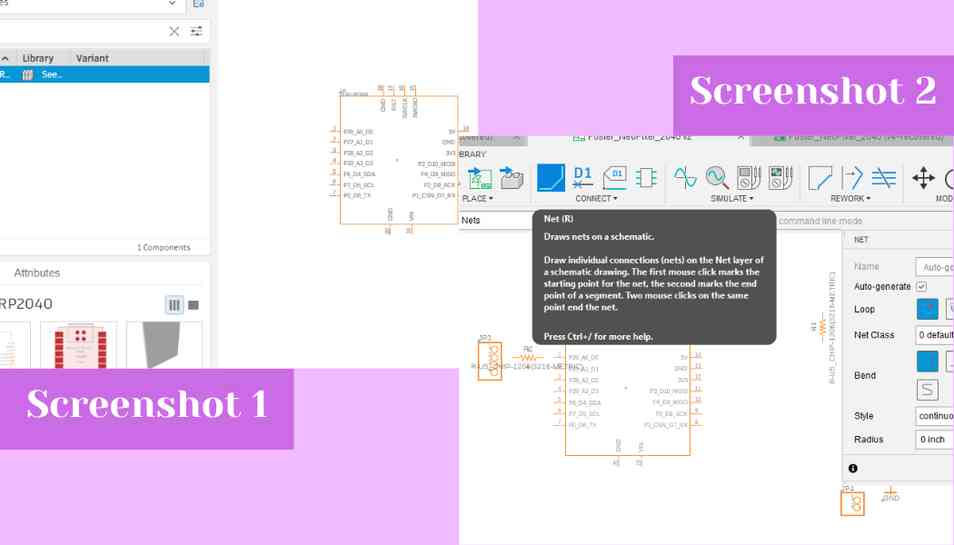
After referencing the Adafruit guide and learning that I likely would need an external power supply if I wanted to control more than 8 NeoPixels, that placing a 300-500 ohm resistor between the microcontroller and the data pin was advisable, and that I should share the ground on the external supply and the microcontroller, I decided to use Eagle in Fusion 360 to create my board for this week. I went in and created a new electronics design from the file tab. I started by dragging out all schematic footprints I would need by searching for them in the left side picker and selecting on each component I wanted (screenshot 1). They are as follows:
- 1 SEEED Xiao RP2040
- 1 1x2 header pin
- 1 1x4 header pin
- 2 1206 SMD resistors
- 1 LED SMD 806
I decided to integrate an LED into my board as an indicator to make sure it was working which is why there is an LED on the board. I also could not find the 1x3 header pins in the schematic library which is why I used the 1x4 header pin. I did later find the 1x3 header pin but must have skipped over it while looking though. Anyways, with all of the components dragged out, I began using the net tool to connect the components together (screenshot 2).
 I used the net tool and clicked on each pin that I wanted to connect and it made a line between the selected pins; I did this for everything I wanted to connect (screenshot 3). With everything netted I switched to the PCB editor by clicking on the PCB icon in the top left hand corner of the schematic editor (screenshot 4). This opened up the PCB workspace and I began by arranging all of my components on the board and by clicking on and dragging in the boundaries of the PCB workspace (screenshots 5 and 6).
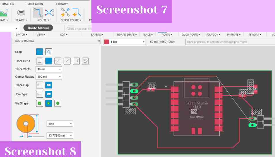
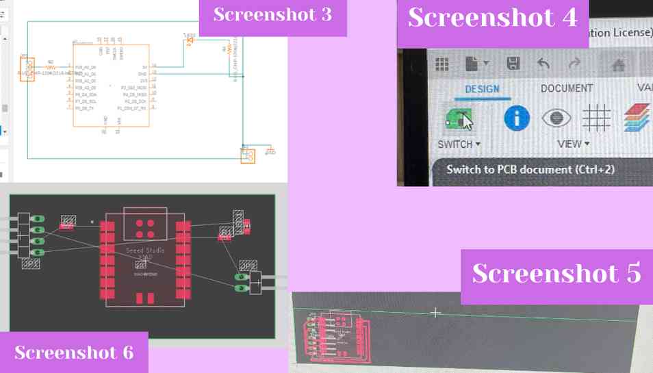 Next I used the manual route tool from the top bar to connect each pad of the footprints together (screenshot 7). I upped the trace width to 10 mil and then clicked on each pad and drew the traces as can be seen in screenshot 8 (screenshot 8).
 With everything routed and traces made, I exported my file as a Gerber by going to the manufacture tab and clicking on that option.
- Board File Download .f3z
- Board File Download .brd
- Board File Download .png (profile and top)
- Board File Download .sch (schematic)
Milling the Board
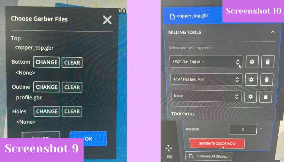
I downloaded my file from our lab’s Google Drive and then went into the Bantam milling software to mill the board. I used a large piece of Nitto tape to affix a piece of FR1 to the mill bed. I stuck with the preset file setup for FR1 boards and uploaded my Gerber files for the copper top and the profile (screenshot 9). I then used the “generate GCODE now” button to turn the Gerber file into GCODE that the machine could read (screenshot 10).
 From there I installed a 1/64” two flute up cut flat endmill bit and then milled the file. The job stopped about halfway through to change bits to the 1/32” two flute up cut flat endmill for the edge cut and larger areas of the design. (screenshot 11). After it was done milling I pried the FR1 up from the bed using a putty knife, and then I soldered my components to the board. The components list is as follows:
- 1 SEEED Xiao RP2040
- 1 group of three 90 degree surface mount header pins
- 1 group of two 90 degree surface mount header pins
- 1 red LED
- 1 330 ohm SMD resistor
- 1 474 ohm SMD resistor
From there I installed a 1/64” two flute up cut flat endmill bit and then milled the file. The job stopped about halfway through to change bits to the 1/32” two flute up cut flat endmill for the edge cut and larger areas of the design. (screenshot 11). After it was done milling I pried the FR1 up from the bed using a putty knife, and then I soldered my components to the board. The components list is as follows:
- 1 SEEED Xiao RP2040
- 1 group of three 90 degree surface mount header pins
- 1 group of two 90 degree surface mount header pins
- 1 red LED
- 1 330 ohm SMD resistor
- 1 474 ohm SMD resistor
Note on milling and testing
The first time I made this board, (screenshot 12, try 1) when I tested it some part of it (I am not sure which) popped and the two power supply wires got very got. I should’ve seen this short coming for a few reasons which I shall list below:
1. There was a very obvious trace rip (see yellow circle on screenshot 12)
2. The soldering job on the left side resistor was horrible, as was the soldering on the LED and the power supply header pins
3. The solder bridge from the left side resistor and the LED onto the large copper islands in the center of the board meant that the 5V supply of the SEEED Xiao RP2040 was going to the data pin of the NeoPixels which is very not good!!
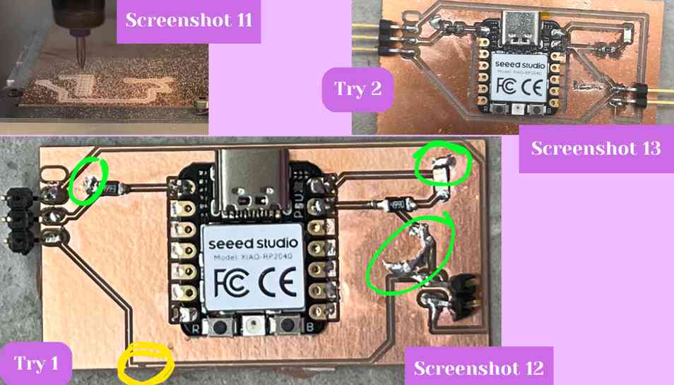 After learning from that experience that a ripped trace cannot be haphazardly fixed nor can you solder onto the copper islands because they touch other things too, I re-milled the board and tried again (screenshot 13, try 2). The second time was vastly better and I didn’t rip a trace or solder poorly with the exception of something I will mention below. Anyways, back to regularly scheduled programming :)
Testing
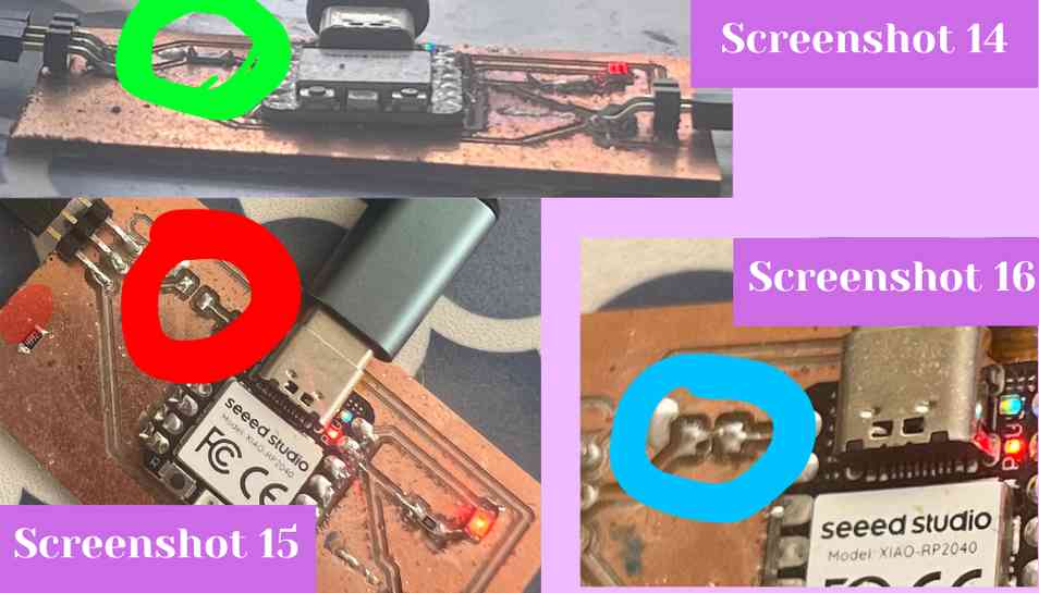
To see if my board worked, I plugged in a test strip of NeoPixels, the 5V power supply, and the USB-C cable and then uploaded the “simple” code from the Adafruit NeoPixel library. I swapped out the pin to pin D0 and the number of pixels to 2. When I uploaded the code though, even though the LED was on, the NeoPixels did not light up. I found this perplexing and took a multimeter to my board to see what the issue was. I first tested the voltage on the NeoPixel pins to see if it was getting any, it was getting the 5V like it should be, so I also did this for the power supply pins, and they were also correct. From there I decided to use the continuity feature of my multimeter which checks for a connection across two different points in a circuit. This is useful because you can see if a part of your circuit is even connected together. I went through with the continuity test for each part of my board but when I checked the data line going to the NeoPixels, the multimeter did not beep like it should when two parts are correctly connected. I tried a few times and still got nothing so I realized that some part of the resistor was not soldered correctly (see resistor in question in green circle of screenshot 14). To fix this to took off the resistor from my board because it is an optional component that is not necessary to the functionality of the NeoPixels. I heated up each side of the resistor and pulled it off the board (de-soldered resistor pads can be seen in red circle of screenshot 15). I then created a small solder bridge across the space left behind and took a razor blade to slice the copper between the resistors pads to ensure I did not create a bridge that connected to the copper island (solder bridge can be seen in blue circle of screenshot 16).
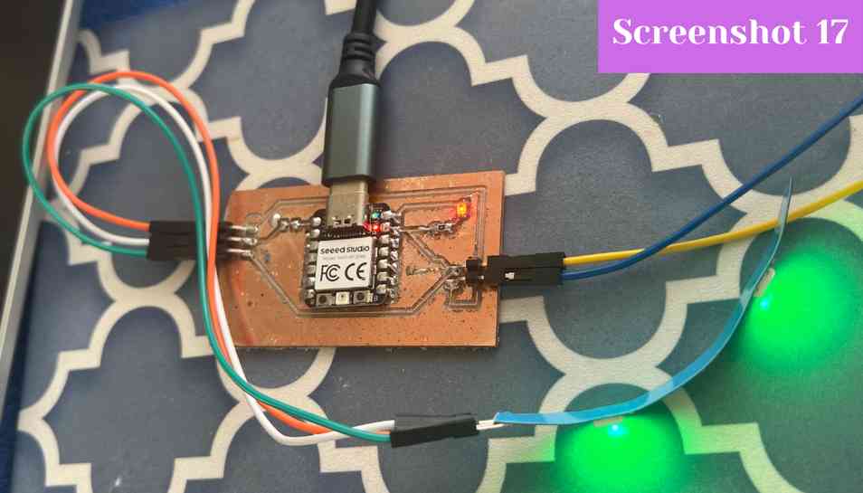
 After I fixed the resistor, I re-tested the continuity of the data line and the multimeter beeped like it should to indicate continuity. After this was fixed I plugged my SEEED Xiao RP2040 back into my computer and the NeoPixels started flashing green immediately like they were programmed to do (screenshot 17).
Final Code
// NeoPixel Ring simple sketch (c) 2013 Shae Erisson
// Released under the GPLv3 license to match the rest of the
// Adafruit NeoPixel library
// Modified by Ginny Foster during Fab Academy 2023

#include <Adafruit_NeoPixel.h>
#ifdef __AVR__
 #include <avr/power.h> // Required for 16 MHz Adafruit Trinket
#endif

// Which pin on the Arduino is connected to the NeoPixels?
#define PIN        D0 // On Trinket or Gemma, suggest changing this to 1

// How many NeoPixels are attached to the Arduino?
#define NUMPIXELS 2 // Popular NeoPixel ring size

// When setting up the NeoPixel library, we tell it how many pixels,
// and which pin to use to send signals. Note that for older NeoPixel
// strips you might need to change the third parameter -- see the
// strandtest example for more information on possible values.
Adafruit_NeoPixel pixels(NUMPIXELS, PIN, NEO_GRB + NEO_KHZ800);

#define DELAYVAL 500 // Time (in milliseconds) to pause between pixels

void setup() {
  // These lines are specifically to support the Adafruit Trinket 5V 16 MHz.
  // Any other board, you can remove this part (but no harm leaving it):
#if defined(__AVR_ATtiny85__) && (F_CPU == 16000000)
  clock_prescale_set(clock_div_1);
#endif
  // END of Trinket-specific code.

  pixels.begin(); // INITIALIZE NeoPixel strip object (REQUIRED)
}

void loop() {
  pixels.clear(); // Set all pixel colors to 'off'

  // The first NeoPixel in a strand is #0, second is 1, all the way up
  // to the count of pixels minus one.
  for(int i=0; i<NUMPIXELS; i++) { // For each pixel...

    // pixels.Color() takes RGB values, from 0,0,0 up to 255,255,255
    // Here we're using a moderately bright green color:
    pixels.setPixelColor(i, pixels.Color(0, 150, 0));

    pixels.show();   // Send the updated pixel colors to the hardware.

    delay(DELAYVAL); // Pause before next pass through loop
  }
}
Reflection
This week I figured out how to implement an external power supply into an electronics board and I think this will definitely be helpful in my final project lamp because I will almost certainly need to power more than 8 NeoPixels to cover the scope of the lamp. I also learned that a ripped trace cannot saved be without extreme precision and that I should have just sunk the cost and made another board. I also learned that I don’t need a resistor on the data line and that it actually ended up hindering my design, and thus I might just be better off not using one.