10. Mechanical Design and Machine Design
This week I made the housing, the button panel, and the wheel holder for my group’s soda fountain machine.
My Group’s Work
You can see a copy of my work along with my group member’s Dariyah Strachan, Dylan Ferro, Stuart Christhilf, and David Tian work on the Charlotte Latin Fab Lab site for student group B.
Resin Mixer
Our original idea was to make a machine that poured resin into a mixing cup and then mixed it together. Our machine would do this by moving to the pour spout for part A, pouring part A, moving to the spout for part B, and then pouring part B. From there it would move to the middle where a mixer would mix the two parts together and initiate the exothermic reaction. Once done mixing the machine would return the resin mixture to the user to pour.
Housing For Resin Mixer
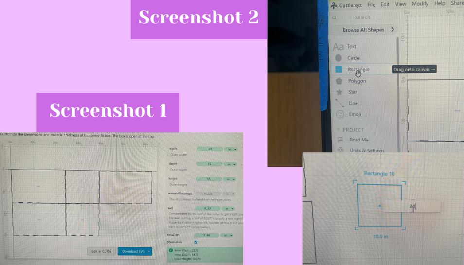
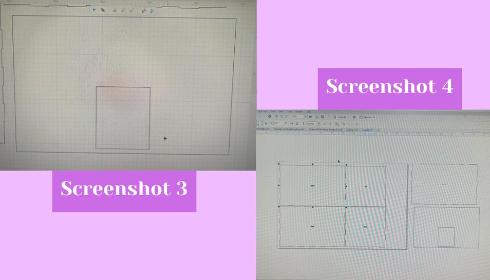
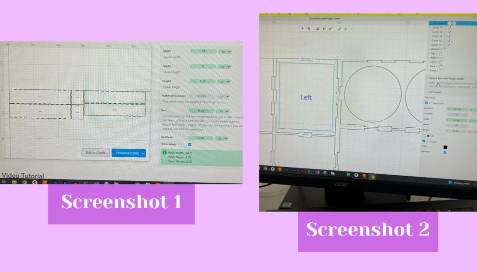
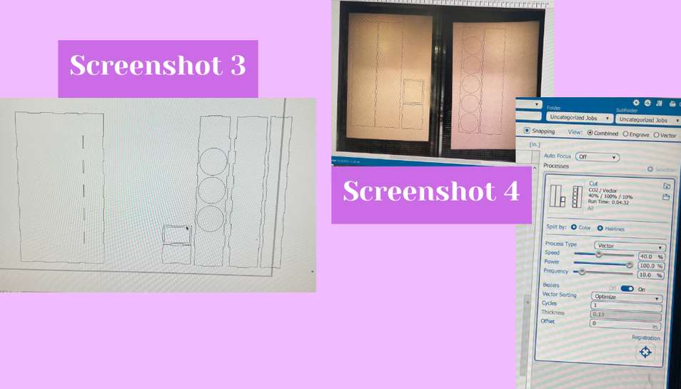
After Stuart Christhilf made the design sketches our group planned everything out together and came to the consensus that we wanted our machine to be a certain size. With that knowledge I could begin making the first prototype for the housing. I started designing in Cuttle because I knew that cuttle had a tabbed box generator. Though we knew we didn’t want our box to be tabbed in the final design making a tabbed box was a good place to start. I began by navigating to the templates tab which is where the various examples of customizable projects like tabbed boxes exist. From there I clicked on the open tabbed box example because we wanted a 360 enclosed machine with a door (screenshot 1). Next, I began changing the width, depth, height, kerf, and tab length of the box. This was all very easy to do because all you had do was type in the desired measurement. I typed in 24 inches for width, 15 inches for depth, 15 for height, 0.02” for kerf, and 1” for tab length. This resulted in something like what I was looking for and all I had to do was make a rectangle that would be the door. I did this by dragging a rectangle onto the workspace and then used the handles to make it the right dimensions (screenshot 2 and 3).
 The door would attach via hinges. With that I could export the file to be laser cut. I imported the design into Corel Draw so that I could make the lines hairline and ensure that it would cut correctly (screenshot 4).
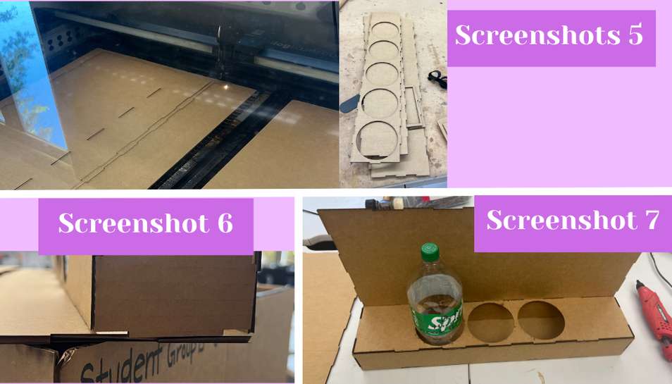
 With that I could send it to the laser cutter to be cut on cardboard. Inside the epilog printer interface I set the cut settings to cardboard (screenshot 5). With that after positioning the design atop the cardboard inside the interface I set it to cut (screenshot 6).
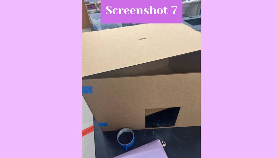
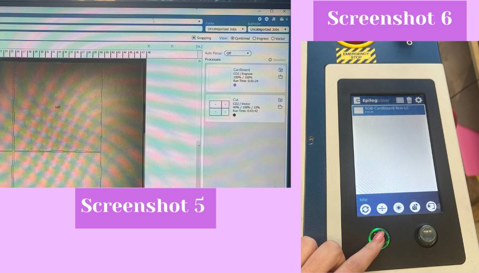 After it cut I took everything out of the laser cutter and began hot gluing the pieces together after fitting it together. Once everything was hot glued together I could mimic the hinges on the door by using tape to attach the door to the front (screenshot 7). Once everything was together I was done.
This however did not last because we ended up changing the design for our machine and thus this box became obsolete. We did however end up using the box for storage for our other project.
Drink Fountain
After we discovered that the viscosity of resin parts was probably too thick, as a group we decided to pivot to making a drink fountain because the concept was similar to the resin mixing machine. We could also use some of our existing ideas in the drink fountain.
Button Control Panel
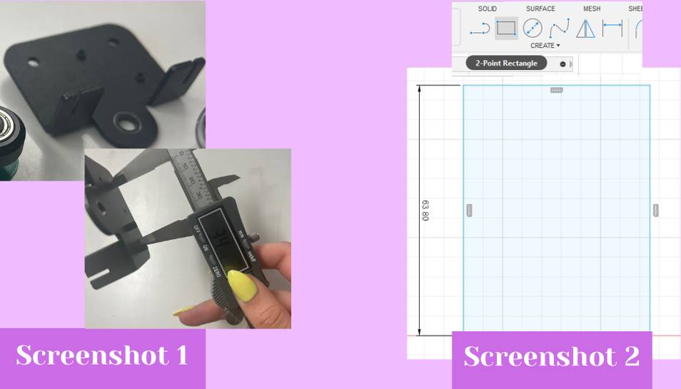
I began by making the control panel that would hold the buttons. The panel needs to hold the on/off button, the start button, and the three buttons for the different sodas/syrups. I began in Fusion 360 where I made a base rectangle that was 5.7 inches by 5 inches (screenshot 1).
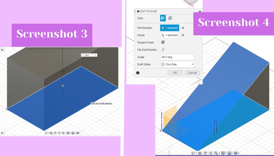
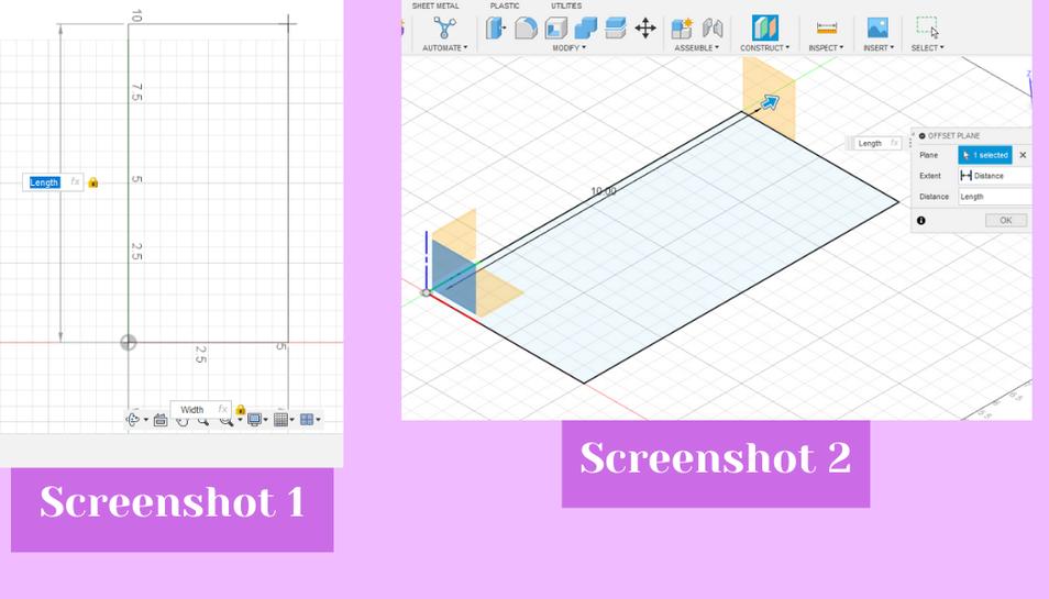 I then extruded that up an arbitrary height that looked right because the height did not matter (screenshot 3). This ended up being 3.29 inches tall. From there I used the draft tool from the modify drop down menu to get a ramp down on the rectangle I just made. I selected the pull direction as the bottom face and the faces as the front face where I wanted the ramp to be (screenshot 4).
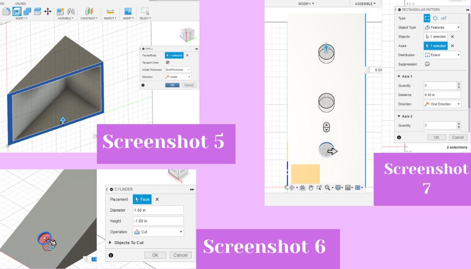
 From there, I shelled the inside of the triangle I made using the shell tool from the modify drop down (screenshot 5). Next to make the cylinder holes I used the cylinder tool from the create drop down. To use it I selected the sloped plane as the plane I wanted it on and then selected the middle of the face as the center point and then the diameter as a little large than I measured the button as (screenshot 6). To measure the button I used a pair of calipers. From there I dragged the cylinder down to intrude it and cut into the sloped plane all the way through. Next, I used the rectangular pattern tool from the create drop down to duplicate the cylinder hole three times. Inside the rectangular pattern dialog box I changed the object type to features and selected the cylinder hole I had just made to pattern (screenshot 7).
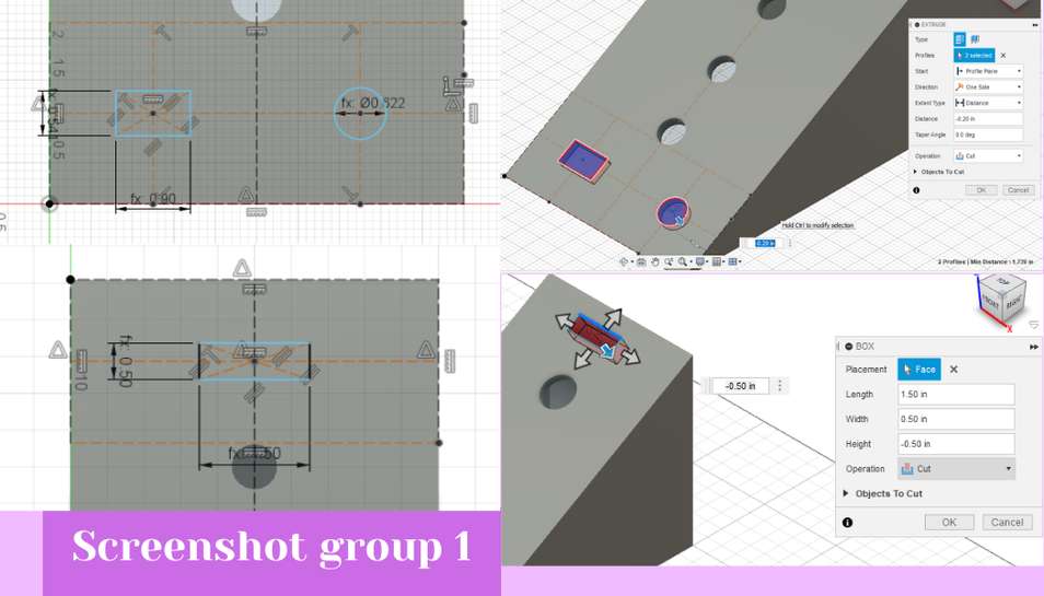
 From there I could just choose three as how many I wanted and I could drag the arrow out until the distance of the three holes looked correct. Next, I I created a sketch on the top plane of the panel for the the other circular button but I made this hole on the right side of the top button panel (screenshot group 1). From there I added a rectangle in the sketch environment and the hit shortcut letter “e” to take me directly from the sketch environment to the 3D workspace where I could intrude the button holes by entering a negative value for the extrude command (screenshot group 1).
 From there I was done so I could 3D print the control panel. I did this by exporting the file as an .stl from inside Fusion by hitting file, then export.
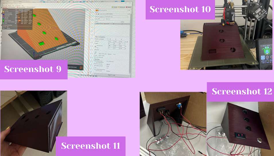
To get the file ready to print I opened Prusa Slicer. Inside Prusa slicer I added supports everywhere but after printing it I realized that if I had rotated it I would not have needed supports, but the day I did this on was very long and personally stressful which is why I didn’t pick up on that when I sliced it. Once I changed the infill to 5%, and the quality to .20 mm speed I sliced the design to turn it into G-CODE (screenshot 9). With the G-CODE I could then upload that to our 3D printers’ website for the printer I wanted to use. Once uploaded I wiped down the bed of the printer with alcohol and then hit print inside the printer’s website. With that I let the design print and came back once it was done (screenshot 10).
When the print was finished I removed it from the bed with a spackle knife. Next, I had to remove the supports and because they were hard to remove by hand I also used the spackle knife to pry off the supports (screenshot 11).
From there we could add the buttons into the control panel and with that the control panel was complete (screenshot 12).
 Though one of the buttons did not totally fit inside the hole because the sides of it were wide and I thought it would just push in. To make it fit Dylan Ferro sanded down the inside of the button hole a little bit until the on/off switch fit in.
Wheels
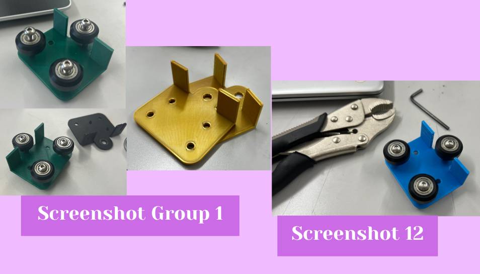
Once our group felt like we wanted wheels to move and guide our machine, I began designing a custom wheel holder for our T bar tracks. I started by looking at a metal bracket and using calipers to measure it’s dimensions (screenshot 1). I used that bracket as inspiration for my own, but I added screw holes so that we could screw the drink plate on to the wheels holders.
I began designing in Fusion 360 by creating a sketch. Inside the sketch workspace I created a rectangle according to what I measured the metal bracket to be(screenshot 2).
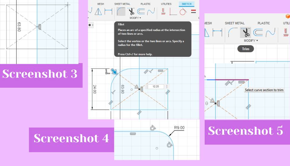
 Next, I added a fillet to the corners of the rectangle, but only two of the corners (screenshot 4). The fillet tool can be found in the ___ menu inside the sketch workspace. Next, I began to add the little bump out for the single wheel. I started by measuring the distance from the top of the bump to the main body of the plate. Next, I added a center point rectangle from the create menu onto the top of the main body rectangle (screenshot 3). From there, I used the fillet tool to fillet the rectangle 9mm until it looked pretty close to circular on the filleted edges (screenshot 4). I also then deleted the unnecessary lines of the rectangle using the trim tool from the modify menu (screenshot 5).
 Following that, I added the center circle for the screw in the filleted bump out I just made. I measured the distance from the edge of the inside of the circle to the outer edge of the curve and then referenced that measurement to make sure my hole was the right size. I measured the distance from the outside of the bracket to the edge of the screw holes and then took that distance for the referenced lines. Where the two intersect is where the center of the screw holes needs to be A(screenshot 6). From there I hit shortcut letter “L” to begin drawing referenced lines. To make the lines referenced lines you have to change them to construction lines. To do this you hit the little construction line button in the right side tray inside the sketch environment (screenshot 7). I then added a circle by hitting the “c” shortcut. I added two circles and then dimensioned them according to what I measured the bracket wheel holes to be. I then hit “e,” the shortcut to extrude and I extruded the sketch up 2.5 mm (screenshot 8).
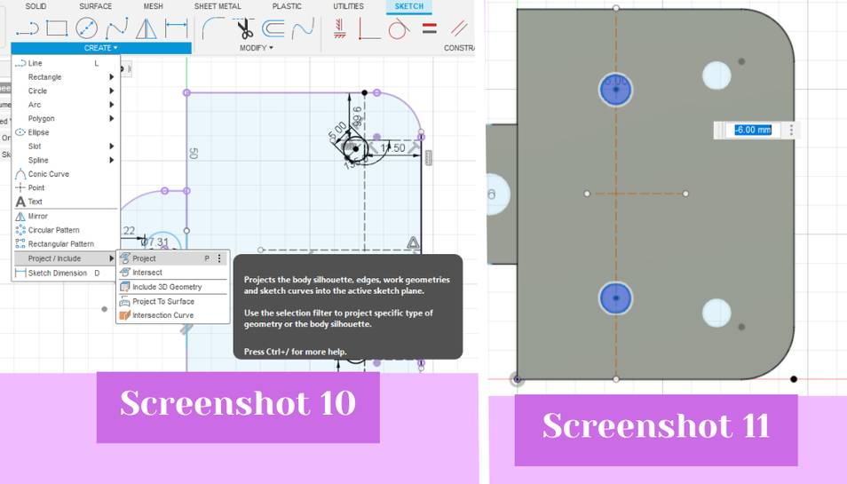
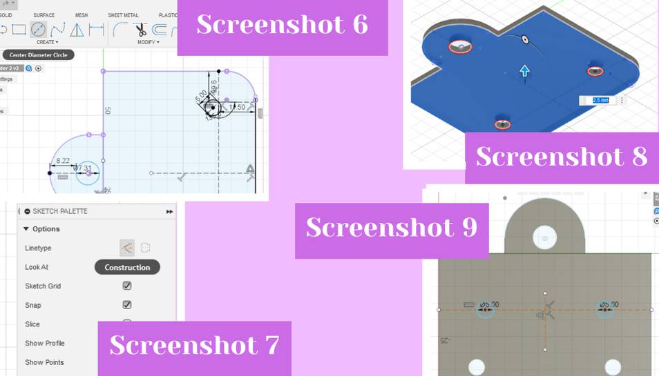 With that made I created another sketch on the top surface of the piece I just extruded, I then projected the outer dimensions so I could referenced them by going create, project/include, then project (screenshot 10). I then added a circle by hitting the “c” shortcut. From there I added two screw holes in the middle of the main rectangle body to screw the plate onto the wheels (screenshot 9). I then hit “e,” the shortcut to extrude and I intruded the sketch down 6 mm (screenshot 11).
 Later though, these would be removed as once I had my final design Dylan edited it for his updated plate. Dylan also added an elevation step to the design so that the plate would not risk hitting the motor should the machine malfunction. Once I had the design done I extruded it up and then added a rectangular box from the create menu to the bottom of the design, like the bracket had, but this later got removed because it only added to the print time and did not really serve a purpose (seen in screenshot group 1 and screenshot 12).
With my design done, I saved it as an .stl and imported it into Prusa Slicer. Inside Prusa Slicer, I changed the infill to 5% to reduce on print time, and I also changed the quality to .20 mm speed again to cut down on print time. From there, I hit the slicer button to generate the G-CODE. Next, I uploaded the design to our labs 3D printer specific website. Before printing, I wiped the print bed of the printer I wanted to use with alcohol, and then I hit the print button inside the website to start the print.
Once the print was done, I removed it from the print bed, and then I could begin attaching the wheel onto the holder. I did this using a pair of vice grips, and an Allan wrench (affectionately known as an Ikea wrench :) ) (screenshot 12).
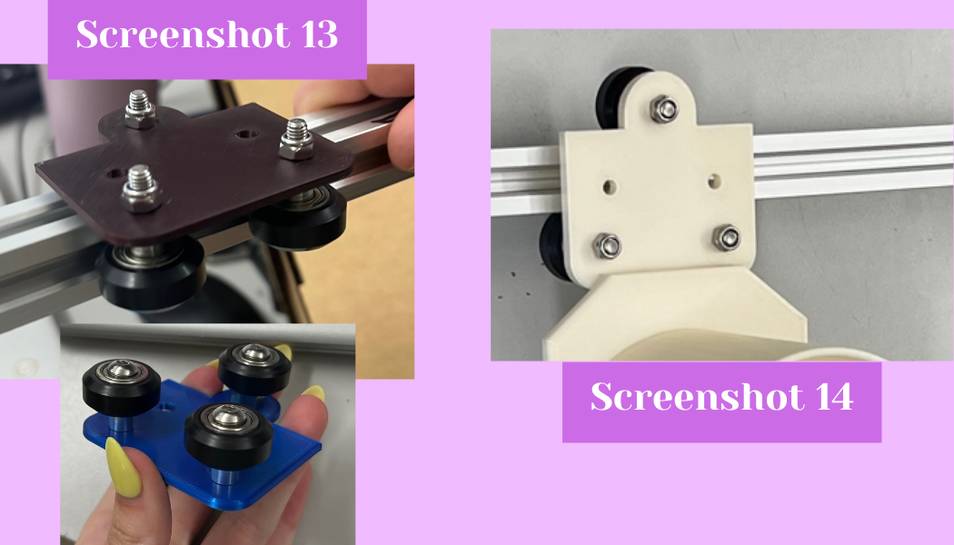
 I added the wheel and the spacer onto the bolt and then slid that through the hole in the plate. Next, I added the nut to the other side of the bolt and I held the nut in place with the vice grips so I could screw the bolt into it. From there I used the Allan wrench to screw the bolt into the nut until it was fairly well attached. With one attached I did the other two using the same method. Then I could test it out on the T tracks (screenshot 13).
The first one slid very well up and down the T tracks, however if you put too much force on them, the tracks would derail which our group thought would be a problem because sometimes liquid can be deceptively heavy. Knowing that I went back into my design and moved the two holes about first about .1 mm and then on the second try 2 mm in the direction of where the tracks would go. After making those changes I re-printed the design and after moving them 2 mm the tracks fit perfectly and did not derail.
After changing the plate design that would hold the cup, Dylan modified my existing design to add some blocks to elevate the plate and remove the extra set of holes because the plate would just be glued to the wheel holders instead of bolted (screenshot 14).
Drink Bottle Holder
The last thing that I made for our machine was the back housing or the thing that holds the drink bottles behind the machine and also holds up the pumps above the cup.
Initially David Tian was going to make the back wall that held up the pumps and I was going to make the drink bottle holder, but I realized that I could connect the back wall to the drink bottle holder so I took over both parts.
I began my design in Cuttle because I knew that a tabbed box we be the fastest and easiest way for our group to get housing and I knew that Cuttle had a tabbed box generator. I used the box generator that had six sides because I knew I needed all sides to have some type of covering. I started by typing in the dimensions of the drink holder part of the housing. I made it 25” long x 5” deep x 3.33” high because that is what our group thought the measurements should be and these measurements also align with the button control panel so the two would seamlessly fit together (screenshot 1). With that I could begin editing the tabbed box Cuttle made me. I began by measuring the diameter of a 2 liter soda bottle so I could take that measurement and turn it into a hole for the drink bottle to sit in. With that measurement I dragged out a circle and changed it’s diameter to 4.4” which was slightly larger than the bottle’s diameter (screenshot 2). I copied and pasted that circle two more times and then dragged it onto one of the top faces of the box. I moved them to the center of the top lid because I knew we needed space for the electronics in the final machine. From there, I added a rectangle to one of the short sides of the box and made it’s measurements slightly smaller than the outline of the tabbed box (screenshot 2). This was for the electronics so that the wires from the back of the buttons in the control panel could connect directly into the electronics storage in the drink holder.
 Next, I added two lines to extend the tabs of the side of the short box because when I tested my original box with a back wall design I did not account for the extra tabs which I needed to remove (see screenshot 6 below). From there I needed to make one long side of the box 14” tall to hide the drink bottle and act as the back wall. To do that I had to override the tabbed box algorithm that cuttle uses by clicking directly on that side of the box in the left hand menu, and then I could click on the side, scroll down in the right side menu until I saw the scale line of information. In the scale it has the variables for the tabbed box, but I could delete one of the variables and type in my own value to change it. This is what I did and I changed it to 14”. From there I was done in cuttle and I exported my file as a .svg. So I could do some final editing in Corel Draw.
Inside Corel Draw I clicked file, open, and then clicked on the .svg Cuttle file to open the file I made in Cuttle. In Corel Draw I used the segment delete tool from the left side tools menu to delete the tabs on the short sides of the box. I also removed the text labels from each box side because they were not necessary (screenshot 3). Once done I selected the entire design and made all of the lines hairline in the top bar so that when they get laser cut.
After Corel Draw I hit the print button on the computer to send the file to the laser cutter. I initially cut on cardboard to ensure my design was correct. When I hit print it opened the epilog printer interface and I began assigning the print settings. I imported the cut settings for cardboard by hitting the file icon and then I clicked on the vector cut settings for cardboard (screenshot 4).
 Next I focused the laser cutter for the cardboard that I put on the cut bed. I did this by using the manual focus on the laser cutter menu. Next, I hit send on the printer interface to send the design to the laser cutter. From there on the laser cutter I hit the play button to start the cut (screenshot 5).
After it cut, I removed all the pieces from the bed (screenshot 5, right). I then assembled the box by laying everything out and then hot gluing all of the pieces together. I placed the side wall against the bottom first and as Dariyah Strachan held the pieces together for me, I took the hot glue gun and went down the seam of the two pieces. We did this for all of the box parts and then let the glue cool (screenshot 7). On the first version I cut I realized the problem with the tabs and then made the fix I described above (screenshot 6). The second version was way better and so I went with the design for the final cut.
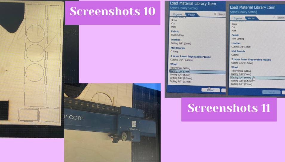
 To cut the final version I extended the back tabs on the top and bottom pieces because I was using 1/4” material for the back wall and the tabs needed to fit into the material. Everything else I kept the same because the wood I was using was going to be 1/8” like the cardboard. I following the same cutting procedure for the wood as I did for the cardboard except I imported the 1/8” vector settings for the 1/8” wood and the 1/4” vector settings for the 1/4” wood (see screenshot 10 and 11 below).
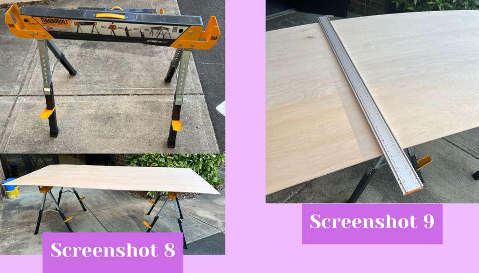
It is worth noting that I had to go and fetch some 1/4” wood from out lab’s wood shed. Because the piece was from a hardware store it was very large it had to be cut to fit inside the laser cutter. My instructor Mr. Tom Dubick used a table saw and cut it for me because we are not allowed to use the circular saw because it can take fingers off much more easily than a reciprocating saw or the table saw. I did have to set up the saw horses and put the wood on the saw horses, but that was not that hard because the saw horses had directions on them and I could lift the wood up on the saw horses myself (screenshot 8). After setting it up and drawing the cut lines Mr. Dubick can out and cut it for me (screenshot 9).
 After he cut the wood I took the smaller piece and loaded it into the laser cutter and then cut it. I also had to change the vector setting in the print interface to cut 1/4” wood (screenshot 11).
 After it was cut Dariyah helped me again hot glue the wood version together as best we could. Most of it did not need to be glued together because it was a perfect fit together with a little percussive maintenece but just to make sure it would stay together we put glue inside the top and inside the electronics hole (screenshot 12). From that the bottle holder was done and I tested to make sure that the 2 litere bottles fit in the holes and were hidden from the front. The holder was sucessful so we began putting things in it/on it (screenshot 13). My design files can be found below.