11. Input Devices
This week I used a BME280 sensor to read temperature, humidity, elevation, and pressure to control a NeoPixel strip. I also made a board for this design. Finally, I measured values from a time of flight sensor using the Analog Discovery 2 for group work.
Group work
This week I helped measure the values from an input device, a time of flight sensor, along with some of my group. You can see my work along with my group member’s Dariyah Strachan, Dylan Ferro, Stuart Christhilf, and David Tian work on the Charlotte Latin Fab Lab site for student group B.
Breadboard test
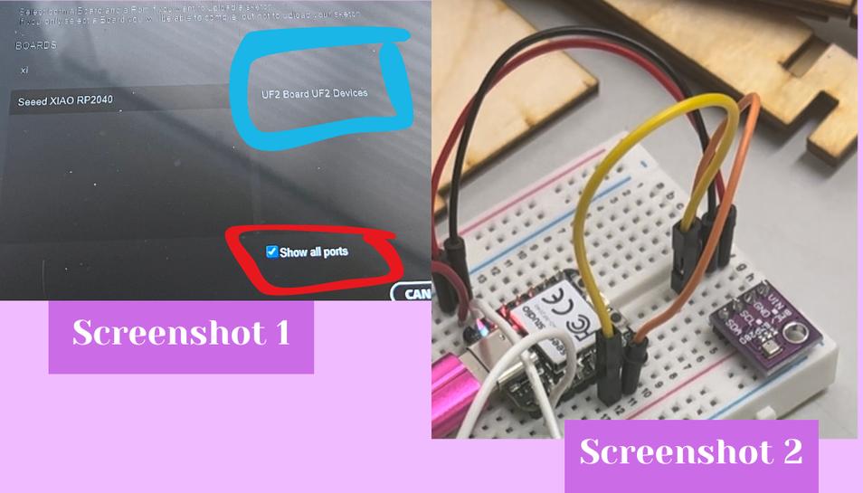
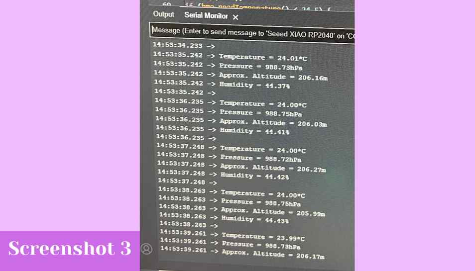
This week our lab tasked us with integrating an input device with I2C into a circuit with an output device and milling a board for it. I began by looking through our lab’s sensors and I found a temperature sensor that had I2C which I though would be cool to do something with. I decided to use NeoPixels as an output because that’s what I would be using for my final project. I began by researching what sensor I had found and I learned from googling that I had a BME280 I2C temperature pressure humidity sensor. Online I learned that I had the version with the I2C pins but that it also came with both I2C pins and SPI pins. I then went to find a tutorial for how to use the BME280 with an Arduino. I found this site which walked you through how to get readings from the sensor. It was for an Arduino, but I wanted to use the SEEED Xiao RP2040, so all I had to do was connect the Xiao RP2040 to the Arduino coding app. I did this by holding down the boot button and then plugging in the USB C to my computer. Then I hit the board selector in the top bar which opened up the board selector interface (screenshot 1). Next, I found the SEEED Xiao RP2040 in the list of board and to select the port I had to click on show all ports to get the port to show up (screenshot 1). Once I had the Xiao RP2040 connected, I copied the code from the website to see if I could get readings from the chip. Then I had to connect the chip to the Xiao RP2040 on a breadboard. I did this by wiring together the VCC –> 5v, GND –> GND, SDA –> SDA, and SCL –> SCL (screenshot 2).
 The code to just get readings is the following:
// from this website: https://lastminuteengineers.com/bme280-arduino-tutorial/
// Used by Ginny Foster during Fab Academy 2023

#include <Wire.h>
#include <Adafruit_Sensor.h>
#include <Adafruit_BME280.h>

#define SEALEVELPRESSURE_HPA (1013.25)

Adafruit_BME280 bme;

void setup() {
    Serial.begin(9600);

    if (!bme.begin(0x76)) {
        Serial.println("Could not find a valid BME280 sensor, check wiring!");
        while (1);
    }
}

void loop() {
    Serial.print("Temperature = ");
    Serial.print(bme.readTemperature());
    Serial.println("*C");

    Serial.print("Pressure = ");
    Serial.print(bme.readPressure() / 100.0F);
    Serial.println("hPa");

    Serial.print("Approx. Altitude = ");
    Serial.print(bme.readAltitude(SEALEVELPRESSURE_HPA));
    Serial.println("m");

    Serial.print("Humidity = ");
    Serial.print(bme.readHumidity());
    Serial.println("%");

    Serial.println();
    delay(1000);
}
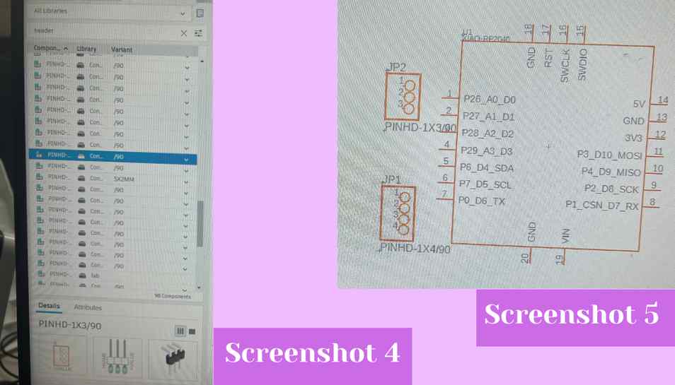
Next, I uploaded the code and it worked and gave me readings of the temperature, pressure, and altitude (screenshot 3).
 Now that I knew that the sensor was getting readings I could alter the code to incorporate the NeoPixels. I started by adding an if statement for the temperature which was the easiest variable I could control by just changing the temperature in my house. I wrote the following to take the measurement of the temperature and if it was less than 27 deg. Celsius then the NeoPixels would start blinking blue and if it was greater than 27 deg. Celsius then the NeoPixels would blink red. I used the code from the simple Adafruit Arduino library for my NeoPixels.
// From this website: https://lastminuteengineers.com/bme280-arduino-tutorial/
// Adapted by Ginny Foster during Fab Academy 2023

if (bmp.readTemperature() < 27) {
  pixels.clear();
  for(int i=0; i<NUMPIXELS; i++) {
    pixels.setPixelColor(i, pixels.Color(0, 0, 255));
    pixels.show();
    delay(DELAYVAL);
}
}
if (bmp.readTemperature() > 27) {
  pixels.clear();
  for(int i=0; i<NUMPIXELS; i++) {
    pixels.setPixelColor(i, pixels.Color(255, 0, 0));
    pixels.show();
    delay(DELAYVAL);
}
}
I also added pixels.begin(); to the void setup() and the following before the void setup().
// From this website: https://lastminuteengineers.com/bme280-arduino-tutorial/
// Adapted by Ginny Foster during Fab Academy 2023

#include <Adafruit_NeoPixel.h>
#ifdef __AVR__
 #include <avr/power.h>
#endif
#define PIN        D0
#define NUMPIXELS 3
Adafruit_NeoPixel pixels(NUMPIXELS, PIN, NEO_GRB + NEO_KHZ800);
#define DELAYVAL 500
From there I added a NeoPixel strip that I had laying around to the breadboard, connected the DO –> D0, the +5v –> 5v pin, and the GND –> GND. The result was the following:
Next I uploaded my code and because the temperature in the room was less than 24.5 the NeoPixels began blinking as they should be doing (screenshot ). Now that I knew that all of it was working together, I began to design my board.
Making a board
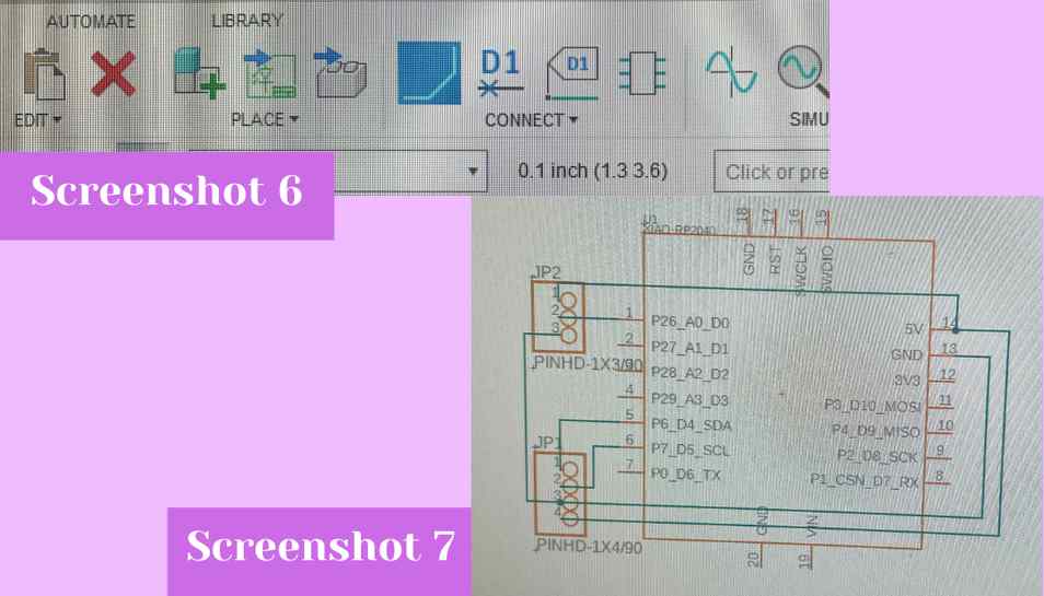
I started in Eagle inside Fusion 360 because I prefer Eagle over KiCAD. To begin I started a new electronics design and I began using the left hand search bar to search and drag out my components (screenshot 4). Next, with the SEEED Xiao RP2040 footprint and the two header pin clusters on my workspace (screenshot 5) I could begin netting my schematic.
 I did this by hitting the net button (screenshot 6) and then by hitting each pin I wanted to connect and connecting it to the other pin I wanted it to be connected to. I did this for each pin I had in my breadboard design (screenshot 7).
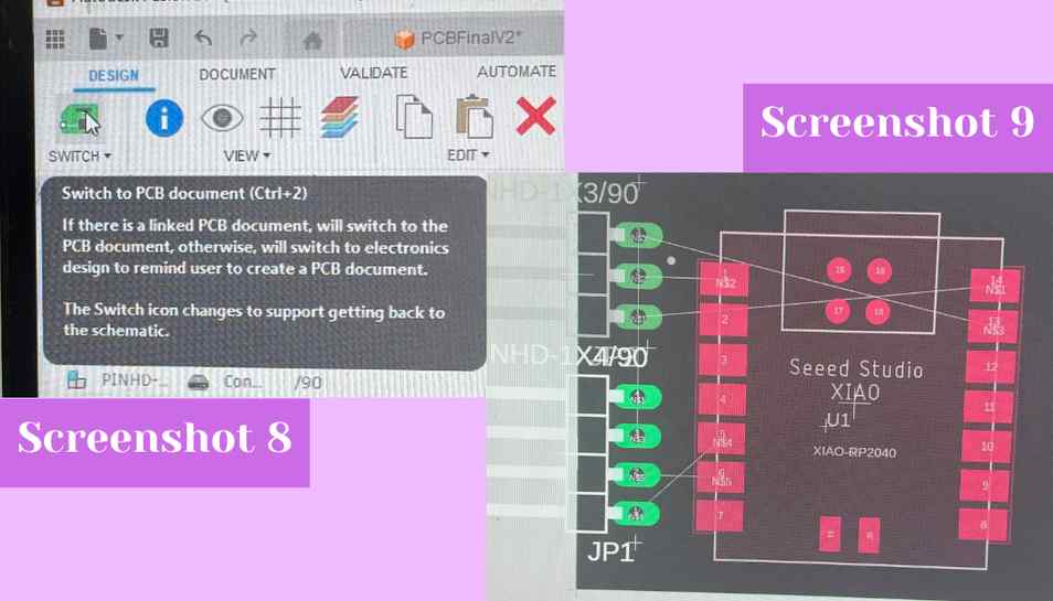
 Once I was done netting my design I switched to the PCB workspace (screenshot 8). Inside the PCB workspace I dragged all of the footprints onto the dark grey work area and then I uses the rotate button to rotate the header pin footprints so they would be oriented the right way (screenshot 9).
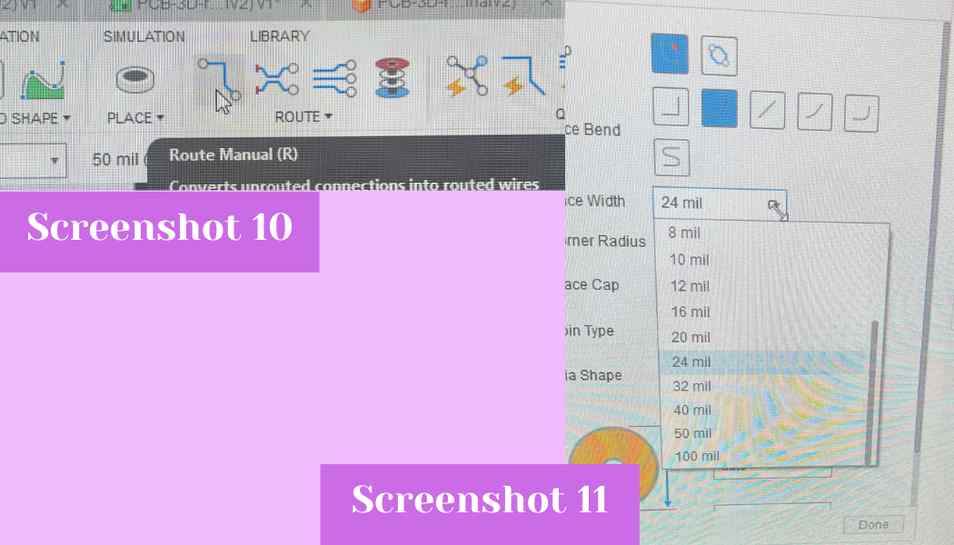
 Next I used the route manual button to route the footprint pads to one another (screenshot 10). I also changed the width of the traces in the dialog box so that the traces would have a lesser chance of ripping once I milled the board. I changed it from 6 mm to 24 mm (screenshot 11).
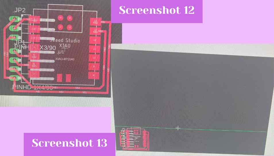
 Next, I changed the size of the board by dragging in the edges of the workspace until I had something that was just the right size for all of my components (screenshot 12 & 13).
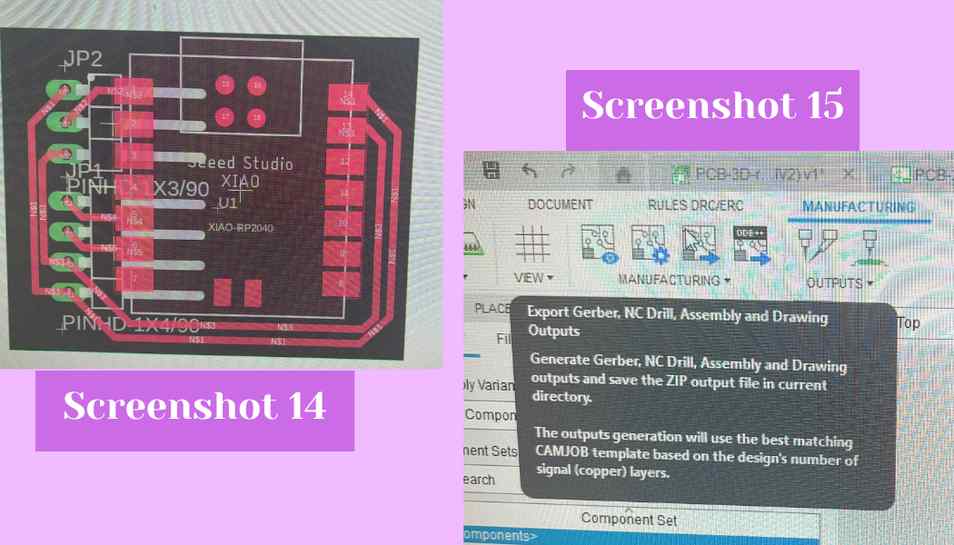
 From there I saved my design and I went to the manufacture tab to export the file as a Gerber (screenshot 15).
Milling my board
I went over to our labs milling machine and downloaded my file from our lab’s google drive. Next grabbed a piece of FR1 and added on Nitto tape to the back of it to stick the FR1 to the bed of the machine (screenshots 16 & 17). From there I installed the 1/64” two flute up cut flat endmill into the machine as that’s the bit our lab uses for small detail work on electronics boards (screenshot 18). From there inside the bantam milling machine software I uploaded my files for the copper top and the profile into the file uploader (screenshot 19). Next, I generated GCODE from the Gerber files by hitting the Generate GCODE Now button below the file uploader (screenshot 20). This created GCODE of my board design. Next I hit mill all in the bantam software and my board began cutting. I had to swap out the 1/64” endmill bit about halfway though the cut and the milling machine paused and prompted me to do so. I exchanged the bit for a 1/32” two flute up cut flat endmill. This bit is used for larger areas on an electronics board being cut and for the profile cuts of boards. After the mill finished I used a vacuum to remove all of the copper shavings from the top (screenshot 21) and then I used a putty knife to pry the board off the bed (screenshot 22).
Soldering and testing the board
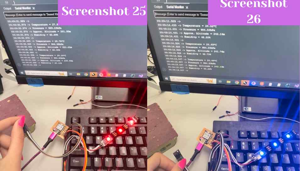
After milling, I soldered a SEEED Xiao RP2040 chip to the board along with 2 groups of 3 and 4 90 degree header pins (screenshot 23). Next I plugged in two ribbons of female to female wires into the header pins for the NeoPixels and the BME280 sensor (screenshot 24). Next, I plugged a USB-C cable into the Xiao RP2040 and then plugged it into my computer to upload the code. Once the code was uploaded I tested how it worked. When I put my finger over the sensor the temperature values in the serial monitor went up as expected as I was hotter than the air in the lab the NeoPixels also turned red as soon as the temperature went over 27 deg. Celsius (screenshot 25). After removing my finger the temperature went back down to the room temperature of around 22 deg. Celsius and the lights changed back to blue (screenshot 26).
// From this website: https://lastminuteengineers.com/bme280-arduino-tutorial/
// Adapted by Ginny Foster during Fab Academy 2023

#include <Adafruit_NeoPixel.h>
#ifdef __AVR__
 #include <avr/power.h>
#endif
#define PIN        D0
#define NUMPIXELS 3
Adafruit_NeoPixel pixels(NUMPIXELS, PIN, NEO_GRB + NEO_KHZ800);
#define DELAYVAL 500

#include <Wire.h>
#include <Adafruit_Sensor.h>
#include <Adafruit_BME280.h>

#define SEALEVELPRESSURE_HPA (1013.25)

Adafruit_BME280 bme;

void setup() {
    Serial.begin(9600);

    if (!bme.begin(0x76)) {
        Serial.println("Could not find a valid BME280 sensor, check wiring!");
        while (1);
    }
}

void loop() {
if (bmp.readTemperature() < 27) {
  pixels.clear();
  for(int i=0; i<NUMPIXELS; i++) {
    pixels.setPixelColor(i, pixels.Color(0, 0, 255));
    pixels.show();
    delay(DELAYVAL);
}
}
if (bmp.readTemperature() > 27) {
  pixels.clear();
  for(int i=0; i<NUMPIXELS; i++) {
    pixels.setPixelColor(i, pixels.Color(255, 0, 0));
    pixels.show();
    delay(DELAYVAL);
}
}
}
Reflection
This week I learned a lot. Previously I had no idea what I2C was but through some research and experience with my sensor I definitely understand it way more. I think that I2C would be helpful in consolidating a project down and also with adding multiple sensors while still keeping everything simple because you only need two pins (SDA and SCL). After this week I can understand the benefit of I2C. Furthermore I got to integrate a sensor in with NeoPixels as an output which will be helpful when working on my final project.