2. Computer Aided Design
This week I worked a few different computer aided design programs including Cuttle, GIMP, FreeCAD, Fusion 360, and CorelDraw.
Trying Cuttle
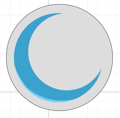
I began following the Cuttle video tutorial posted by Mr. Dubick. The tutorial was on how to draw a dodecahedron candle holder. The tutorial was split into two separate videos linked here and here. It is worth noting that I have briefly used Cuttle before and I absolutely hated it. I tried it in spring 2022 as part of a warm up for my Engineering Design Methods II class taught by former Fab Academy grad Mrs. Barbara Morrow. I tried to make a moon inside a circle (Screenshot 1) that was shaded akin to the Moon Knight moon from the promo images because the TV show had been releasing or was about to release around that time. Made it, but it took almost half and hour because to get the insides of the moon to be different colors was so hard.
Download my past use of Cuttle design
Following The Cuttle Tutorial
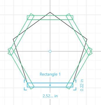
I began video one by adding a polygon as Toby instructed. I used the handles of the polygon to make it bigger, and in the side panel I changed the number of sides it had from 6 to 5. After doing that I dragged a rectangle onto the workspace and manipulated the handles until the rectangle snapped to the corner of the bottom of the pentagon. After getting the rectangle to snap I dragged out the sides until the rectangle was about as big as Toby’s rectangle because he didn’t tell us the exact measurements. Next, to copy the rectangle to all of the other side of the pentagon, I used the rotational repeat feature in the modify dropdown box (screenshot 1).
 I changed the number of repetitions to 5 in the rotational repeat box that open up in the side panel. Next, I made a copy of the pentagon shape that I originally made so that I could set it to score instead of cut if I used the vinyl cutter to make it. To do this I changed the color of the copy of the shape to red in the stroke customization bubble next to the shape in the side panel. Next, I highlighted all of the shaped I had made so far and then right clicked to group them all. With all of them grouped I began making the design for the inside of the pentagon. I followed what Toby did in the tutorial and changed the implement I was using to the pen. This can be done by clicking the fountain pen icon in the top center bar, or by hitting shortcut letter “P.” With pen selected, I held down my mouse button and began drawing a paisley like shape. Whenever I wanted a next line I let go of the mouse and it would create a point. After drawing 4 points with their connecting lines using the pen I began manipulating the points and their dual sided angle handles to get the desired shape. After making my paisley shape I clicked rotational repeat option from the modify drop down menu to repeat the paisley shape 5 times. I then dragged the paisley shapes so that the would snap to the center of the origin. Next, I dragged a circle onto the workspace. I made the circle smaller by using the corner handles of the shape, and then I dragged it so it would be in between the paisley shapes. Then I copied and pasted the circle once to create two small circles that would make a little curve of circles in between paisley shapes. Then one by one I selected each of the circles to rotationally repeat them five times. In hindsight I could’ve just selected all of the circles and rotationally repeated them all at one time, but I decided to make it hard for myself without realizing. Good job me!! Next, I copied and pasted the paisley shape I made and dragged it so that it was in between the circles. I again used the corner handles to make them smaller, but I did not need to rotationally repeat them again because when I copied and pasted them, it also copied the rotational repeat. Then I copied and pasted the two circles I had made before and moved them in between the smaller paisley shapes. I did not resize these circles. Then to break up the circles, I copied and pasted another five paisley shapes. I only moved them to fill the space between the circles, and did not resize them. Next, I copied and pasted the smallest circle I had made and dragged the circles into the middle space of my design. I used the corner handles on the reference circle to resize all of the circles and made them way smaller. To complete my design I dragged out one more circle from the side shape palette to snap to the middle of my design (screenshot 2).
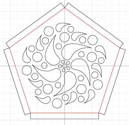 I again used the corner handles to make the circle small enough to fit inside the circle of small circles at the middle of my design. I did not rotationally repeat this circle. Then I used the file tab to save my design as an SVG. You can download my design using the link below.
Cuttle Concluding Thoughts
So I still am not a fan of cuttle, but I think I understand how to use it more than I did ~8 months ago. I like that it can be automatically parametric, or you can freestyle what you want. I am not a fan of the UI though, it is hard to use in my opinion, and it is deceivingly simplistic looking. I would use it again, but I would rather use CorelDraw than Cuttle.
Trying GIMP
I began by installing GIMP from this link and I chose the direct download option from the Windows install options. I followed the following tutorial to try out this raster program. Floating logo tutorial
GIMP Floating Logo Tutorial
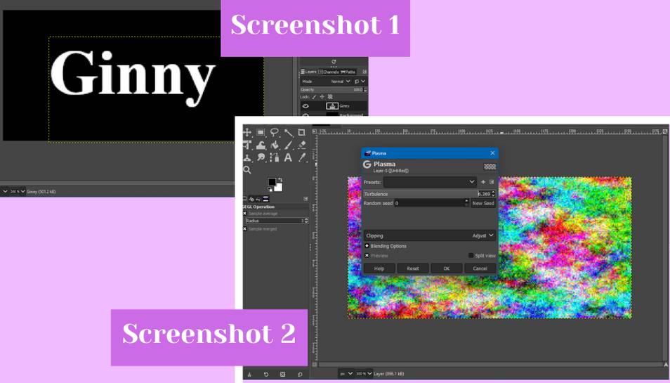
To get started I opened GIMP and navigated to the file tab to create a new project. In the ‘create a new image” dialog box I used the dimensions the tutorial recommends and went with 256 for the width and 128 for the height. I clicked ok to confirm my edits. GIMP then promptly displayed my workspace. I then changed the foreground color to black like the tutorial suggests where the two little squares are located in the left hand panel. Then I used the bucket tool from the tools menu on the left to drop the black onto my image. Then used shortcut letter “x” to swap the foreground and background, and next I clicked on the text icon from the tools menu on the right (looks like a white A) to begin adding text. I drew a rectangle onto my canvas for my text box and used the corner handles of the box to manipulate it to my liking, and then I typed in my name (screenshot 1). The text was automatically white, so I did not have to change the color, but you can if you wish. Then I clicked on the text layer in the layers list and right clicked to select the “New from Visible” option to create a layer from all of the visible layers. Then making sure that I was on the newly create visible layer I went to the filters tab at the top and then went to the Blur menu and selected the “Gaussian Blur” option to blur the text. I left the dialog settings as they appeared and clicked Ok to confirm and apply the blur. Next, I added a layer for the colored part of the final design. I did this by clicking the Layer menu in the top bar and then by clicking “New Layer.” In the dialog that appeared I did not change anything and just clicked ok to create the layer. To add the color to the layer I went to the Filters menu in the top tab and then expanded the Render menu. In the Render menu I clicked the Noise tab and then selected “Plasma” from the menu (screenshot 2). I manipulated the values in the plasma dialog box to make the pattern more pixelated, and then clicked ok to apply it.
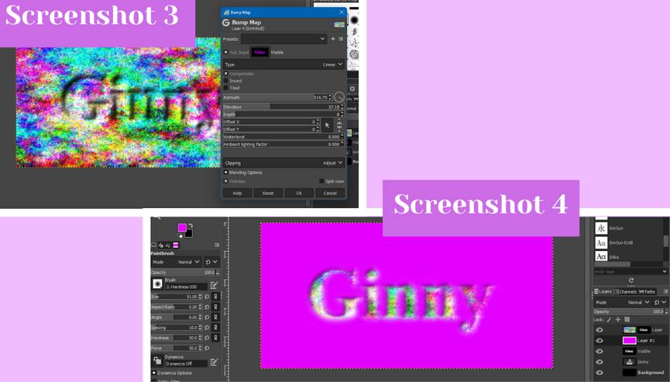
 From there I went to the Filters tab, then to the Map menu, and then I clicked on “Bump Map.” In the bump map dialog box that opens I played around with the Azimuth and Depth sliders until I got something like I wanted (screenshot 3). Next, I added a layer mask to my design by going to the Layer tab in the top bar, then by clicking Mask, and in the Mask tab clicking “Add Layer Mask.” I did not change any of the settings in the dialog box that opened, and just clicked ok to add the mask. I then copied the Visible layer on to the mask I just created by highlighting the Visible layer and going to Edit in the top bar and then clicking “Copy.” Then I highlighted the white box next to the colorful box in the “Layer” Layer of the layers box on the right. With the white box selected I went to Edit in the top bar and then clicked “Paste.” By doing this it adds a floating selection to the layers menu area on the right, and to add it to the “Layer” layer go to the Layer tab in the top bar and click “Anchor Layer.” To add color to the background I create a new layer like I did above and used the paintbrush tool from the tools menu to paint the canvas purple (screenshot 4).
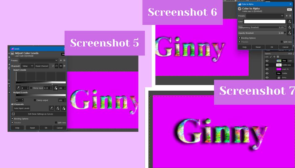
 I then moved this layer below the “Layer” layer with the colorful box to get the color to appear behind my colorful text. To make the edges of my text more defined I highlighted the layer mask layer and then I went to the Colors menu and then clicked “Levels.” In the dialog box that opens I played around with with Input and Output sliders until my design looked more sharp (screenshot 5). Finally, to create a shadow behind the colorful text I copied the “Visible” layer by right clicking it and clicking “Duplicate Layer.” From there to swap the white and the black colors on the layer that was just created I went to the Colors tab in the top bar and then clicked on “Invert.” Then to make the white areas transparent I went to the Layer tab and then to the Transparency tab and then clicked on “Color to Alpha” (screenshot 6). To move the black shadow so that the text looks like it is leaving a shadow I clicked the move icon in the tools menu on the left of the screen. To move the shadow I held down the Shift key and clicked on the canvas to move around the shadow until it looked right. To round the logo off I added another Gaussian Blur like I did above. (Screenshot 7) Then I saved the file to complete this tutorial. You can download it using the link below.
GIMP Concluding Thoughts
So GIMP reminds me a lot of Adobe Photoshop, and not in a good way. I used Photoshop a few years ago in a middle school art class and it was so hard to use and not at all new-user-friendly. From what I used and experienced, GIMP seems to be the same way. GIMP I can tell has many different features that you basically have to experiment with to see how they work. I know I only scratched the surface on its capabilities, but even with the little bit I did pick up, I know I would not reach for this program again. I know from the Fab Academy week 2 website, Pixlr was listed as a raster program that we could use, if I had more time I would use Pixlr over GIMP because I have used it before and it is much easier to use in terms of being new user friendly and the UI is much easier to navigate.
Trying FreeCAD
I began by downloading FreeCAD from this link and following the setup wizard. I followed this video tutorial to try out FreeCAD.
FreeCAD Bracket Tutorial
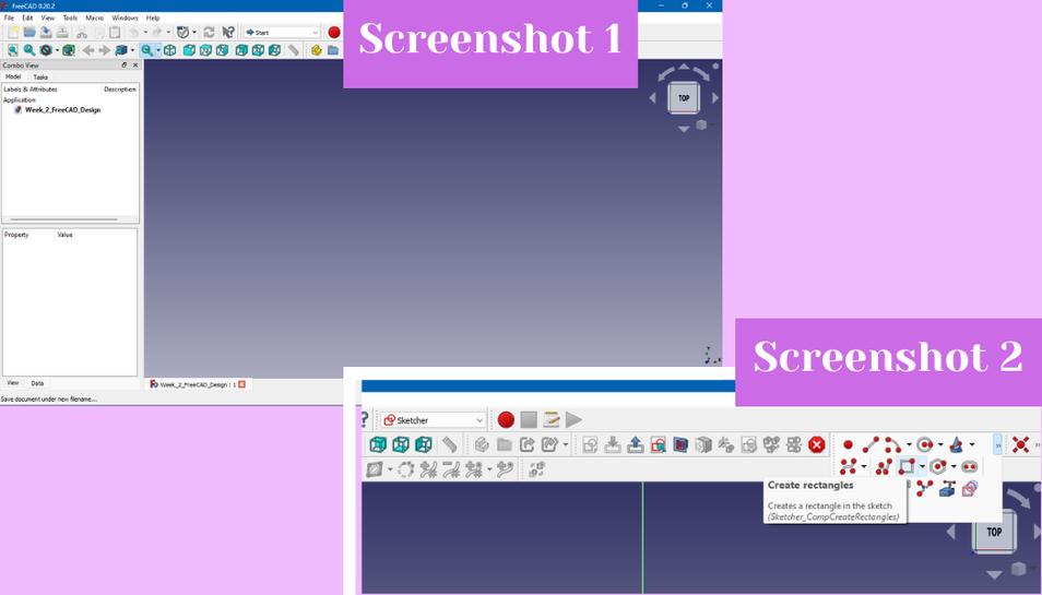
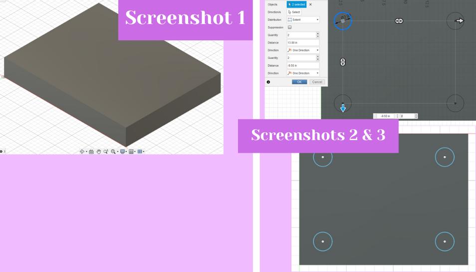
I began by creating a new file from the start page and by saving that file as soon as it opened up (screenshot 1). Then I changed the work bench to “Part Design” from the drop down in the top bar. I found it very hard to find things in the top bar of FreeCAD, so I just hovered over the options until I found the right one as the video tutorial was either outdated or they had set their FreeCAD up differently. In the left hand menu, I clicked the Tasks tab, clicked create body, and then clicked create sketch to begin my design. I chose the XY plane in the left hand menu as the plane I wanted my sketch to be on. I then hovered until I found the sketch geometries palette on the right side of the top bar and then created a center point rectangle (screenshot 2 and 3).
 Then I selected the top line of the rectangle and then found in the sketch constraints palette, the constrain horizontal distance constraint. In the dialog box that open I typed 100mm from the distance. I did the same for the left line of the rectangle, but I chose the constrain vertical distance constraint and typed 50mm for the distance (screenshot 4).
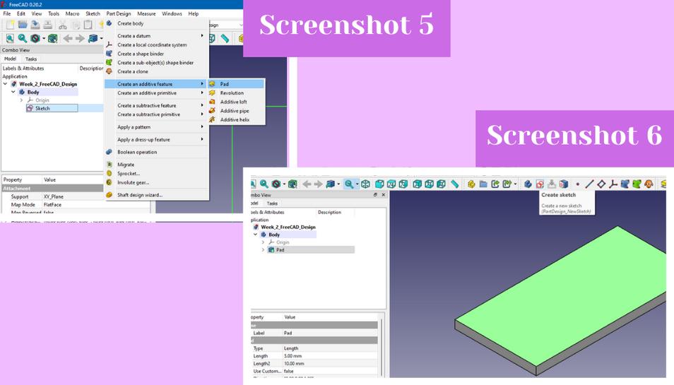
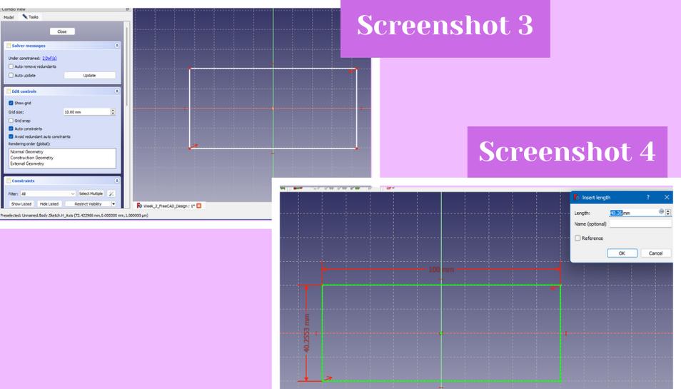 Then I hit close in the combo view left hand tab. In the model tab I clicked on the sketch I just made and right clicked to select part design then clicking on create additive feature and then pad to extrude the sketch (screenshot 5). In the pad dialog box I made it 5mm and then clicked ok. With the box now created, I clicked the top of the box and then clicked on the create sketch option from the top bar (screenshot 6).
 In the sketch workspace I went to the circle creation option in the sketch geometries palette and created four randomly shaped circles in each of the corner of the rectangle (screenshot 7). To make the circles 10mm I first made the one in the top left 10mm by using the constrain diameter from the constrain arc or circle menu in the sketch constraints palette. Then to make the other circles 10mm I used the equality constraint from the sketch constraints palette. To make them the same distance from the edges of the rectangle I began by referencing a point from the rectangle sketch by using the external geometry tool from the top bar. I chose the top left point to reference and clicked on it. Then I left the external geometry tool by right clicking in the workspace. Next I clicked both the left point and the center of the top left circle and horizontally and vertically distance constrained them 10mm (screenshot 8).
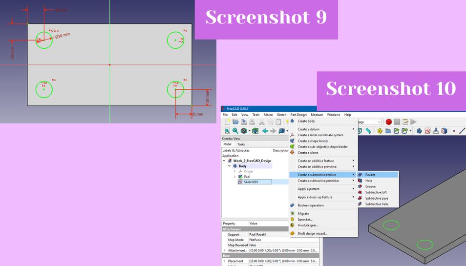
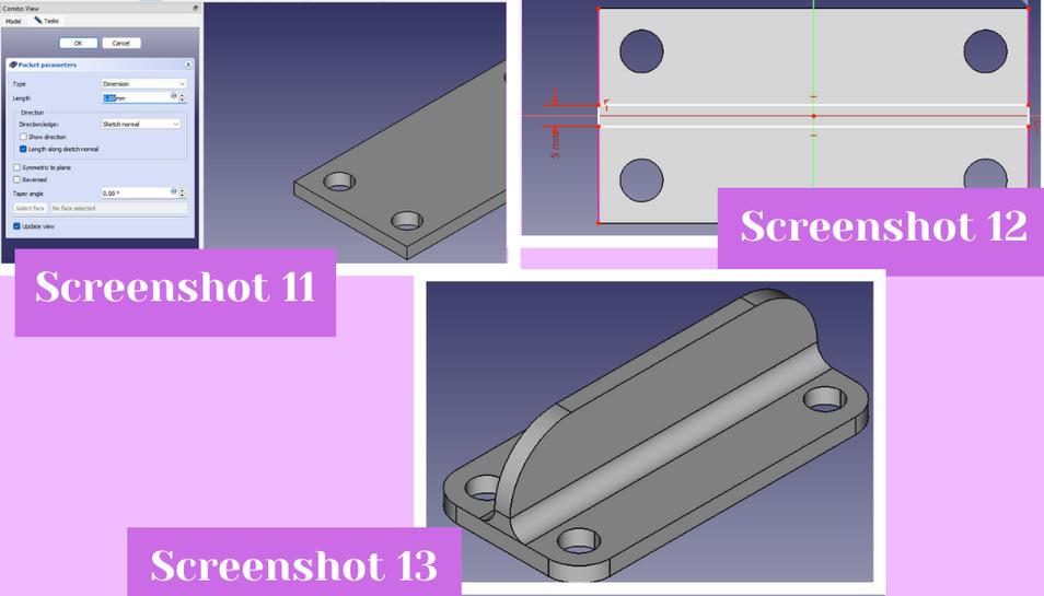
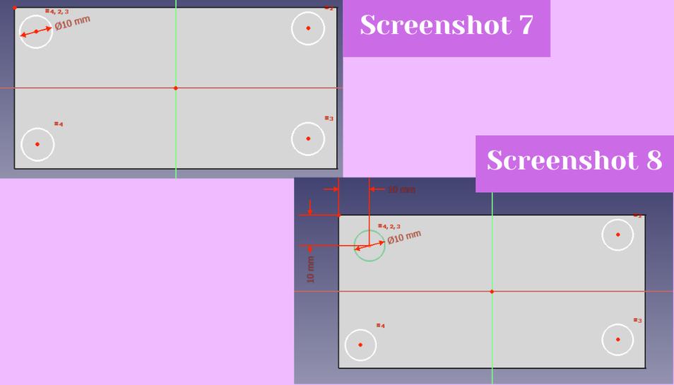 Then I vertically and horizontally constrained the center points of each other circle with the top left circle. To make everything even I finally referenced another point from the rectangle sketch by using the external geometry tool from the top bar. I chose the bottom right point to reference and clicked on it. Then I left the external geometry tool and I clicked both the bottom right point and the center of the bottom right circle and horizontally and vertically distance constrained them 10mm. This evened out all of the circles (screenshot 9). Then I hit close in the combo view left hand menu to return to the part design workspace. There, in the model tab of the combo view menu, I clicked on the sketch I just made and clicked the part design menu in the top bar of the page. From there I clicked on create subtractive feature, and the hit “pocket” (screenshot 10) to create holes of the circles (screenshot 11).
 Then selecting the top face plane of the rectangle again, I created a sketch. I referenced external geometry of the left and right side lines of the rectangle like I did above. Then I created a normal two point rectangle using the rectangle tool from the sketch geometries palette and used the two referenced lines as the first and second point of the rectangle. I then vertically constrained the right and left sides of the rectangle to 5mm (screenshot 12) and closed the sketch workspace from the combo view menu. I then used the pad tool like I did above but instead I raised the rectangle 25mm. With the basic shape done I could now “dress up” my design by adding fillets. To add fillets I selected the lines I wanted to fillet and then click the part design drop down, then the apply dress up feature, and then clicked fillet. In the left hand fillet menu I entered the fillet value I wanted. For the top edges of the divider, I filleted 20mm, for the 4 corner edges of the base rectangle I filleted 10mm, and for the intersection of the divider and the base rectangle I filleted 5mm (screenshot 13). Then I clicked save, and then exported my design as an .stl as I was now finished. You can download it using the link below.
FreeCAD Concluding Thoughts
So I would say that I definitely prefer Fusion 360 over FreeCAD because Fusion 360, in my opinion, is way easier to navigate and use. I do not like how all of the tools are layed out in FreeCAD, and how you have to hover over each tool until you find the right one. FreeCAD also just aesthetically reminds me of what websites from like 2010 looked like which I know isn’t a big deal, but it bothers me.
Fusion 360
Past Fusion 360 Experience
I have been using Fusion 360 for about two years and I feel quite comfortable with it. I began using it in Engineering Design Methods I and we started following Kevin Kennedy’s of Product Design Online learn Fusion 360 in 30 days video tutorials. In that class we only did the first three tutorials, a Lego brick, a bottle, and a paperclip. This gave us enough foundational knowledge for that class. Later, in Engineering Design Methods II we returned to the Kevin Kennedy video tutorials to gain a deeper understanding of how to Fusion 360. We worked though about the same amount as we had the semester prior, but we also followed the whiskey bottle tutorial. Then my teacher Mrs. Barbara Morrow gave us many different objects to 3D model with Fusion 360 from scratch including Lego people, and three or four different types of Legos. Next, in my bioengineering class which I am taking now, we worked through Day #12 of the Kevin Kennedy tutorials to prepare us to use Fusion 360 more in depth. Also in my free time to prepare for Fab Academy, I did nearly all of the Kevin Kennedy tutorials so I could expand my knowledge of the program. Needless to say I feel really comfortable using this program. Because it is the program I feel the most comfortable with, it will be the program I will use to 3D model my potential final project.
Designing Final Project in Fusion 360
I knew that this weeks assignment was to model my final project in one of the software types, so I chose to do this in the program I felt most comfortable in. I wanted to make a rough mock up of what my final project would look like. To begin I made an 14” x 18” sketch from the top bar in Fusion on the XY plane. I then clicked confirm sketch and extruded the sketch 2.5” by hitting shortcut letter “e” (screenshot 1). Next, I set about making the feet holders for the record player. I began by making one circle sketch with a diameter of 2” and then rotationally repeating that sketch twice in the X and Y direction (screenshots 2 and 3).
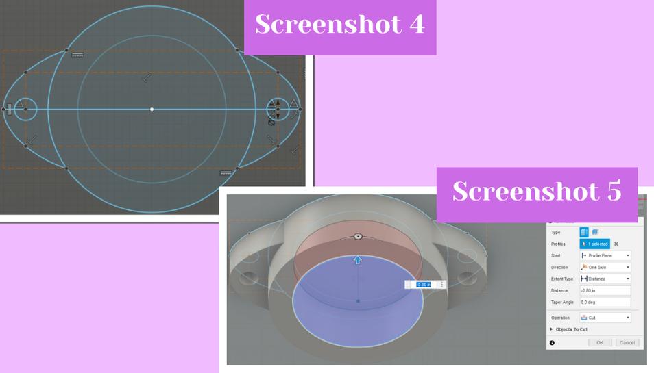
 Then I edited the sketch again and drew another larger circle, snapping it to the center of the previous circle, and also two construction line rectangular boxes for reference. With the two rectangles I used the fit point spline tool to draw an arc starting at the edge of the circle and curving to touch the outside middle of the largest rectangle while also intersecting with the corner of the smaller rectangle. Next, I added small hole designed for a screw inside the arc that I just made. (Screenshot 4) Then, I exited the sketch and went to extrude the sketch I just made by using shortcut letter “e” again. I extruded the center part more than the side brackets that would hold the piece to the base piece of wood. Then I created a new sketch from the plane of the center circle I just extruded to create another smaller circle to intrude into the piece for the material that will eventually sit inside this holder. I drew the circle using the center point circle tool, and once my sketch was finished, I intruded it -0.8” into the piece making sure that it did not go all the way through (screenshot 5).
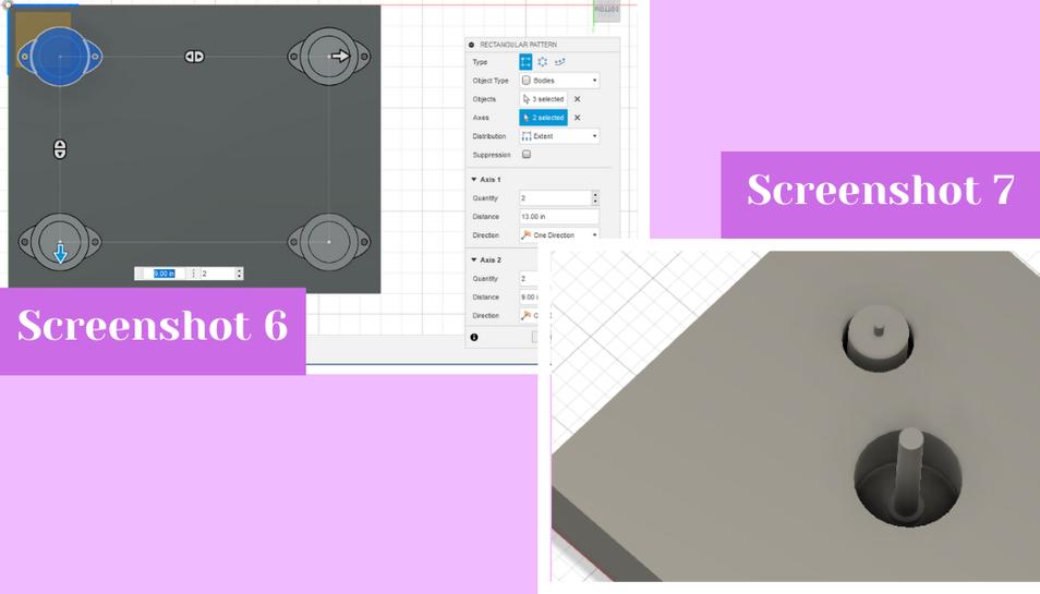
 From there I went to the Create drop down menu in the 3D modeling interface and in the drop down I went to the Pattern menu where I chose the rectangular pattern option again. I changed the object type to bodies and selected the foot holder I just made to repeat twice along both the X and Y axies (screenshot 6). With that done for now, I moved on to the top where I made two circular pocket holes on the top of the base block by making a sketch with two circles and then extruding them a negative amount into the base. These holes will serve as the base pockets to hold the motor and the shaft of the record player, as well as the piece that will hold the platter. I knew that these pockets would likely change in shape and size so I did not put much thought into their size. In the top left pocket I added a simple little mockup of my motor by adding a large cylinder with a smaller cylinder on top of it by again adding circular sketches from the faces I wanted them to sit on. In the middle pocket I added the shaft of the record player that would hold the record and platter as well as be the axis that everything would spin around. I did this by making a small flat cylinder from a sketch on the bottom of the pocket, and then by making a small but very tall cylinder from the center of the smaller circle. (Screenshot 7)
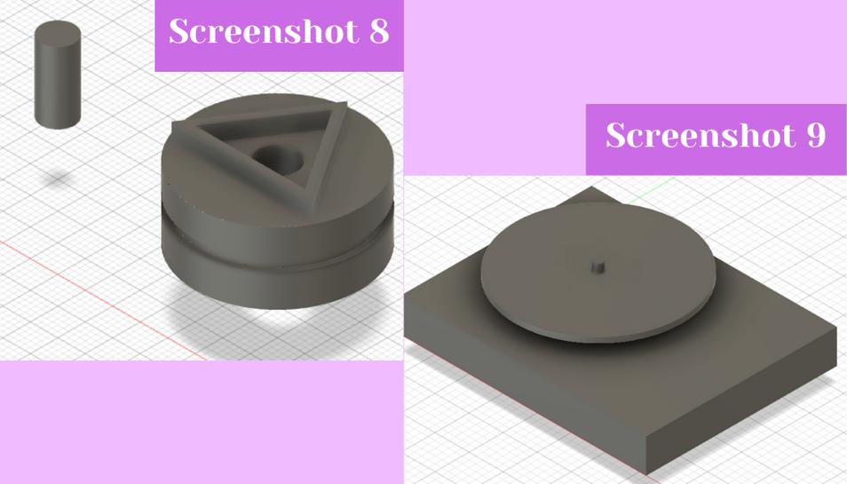
 From there I began making the two small cylindrical pieces that would attach to the motor and the shaft of the record player and allow the motor to spin the platter. I referenced my design from week one to make these pieces. I began by making three cylinders for each piece, stacked on top of each other, but I made the middle cylinder of each a smaller diameter than the other two to allow for a groove for the belt that would spin the platter. I then added a hole all the way through the larger of the cylinders because that one needs to go all the way through the shaft. I only added a small little pocket on the smaller cylinder because that one needs to attach and grip the top of the motor to spin everything. From there I worked on the triangle that would allow the platter to attach to the cylinder and allow it to spin. I knew I wanted it to be a triangle because triangles are my favorite shape and they are also the strongest shapes in nature. I began by creating a sketch on the top of the larger cylinder and by using the line tool, along with a guide line to mirror the left leg of my triangle to the right, I created an isosceles triangle on top of my cylinder. To make the smaller inside triangle I used the “ctrl” key along with the “c” key to copy the shape. Doing this activates the move/copy dialogue box in Fusion 360 where you can scale down your shape and move it around if you so desire. I scaled down the copy of the triangle and then moved it so that it would be in the center of the larger triangle by snapping it to the center of the circles of the cylinder. From there I clicked the finish sketch button and then extruded the triangle sketch up about 1/4”. (Screenshot 8) Next I created an offset plane by going to the Construct menu in Fusion and choosing the offset plane option. I made this offset plane from the top of the shaft of the record player to start the sketch of the platter. With the offset plane made, I created a sketch on the plane of two circles, one outer circle with a diameter of 12.2” and then a small inner circle which would attach to the shaft and is thus only slightly larger than the diameter of the shaft. With the sketch made, I extruded this up about 1/2” (screenshot 9).
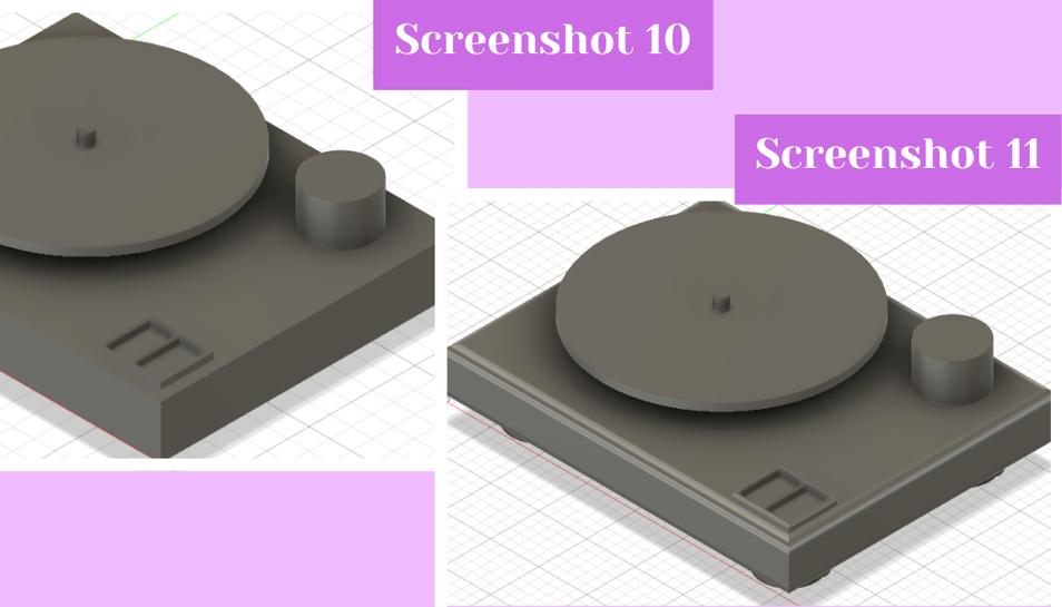
 Next I added a placeholder for the needle of the record player, as well as a placeholder for the on/off buttons for the motor and the other electronics. I did this by creating a sketch from the top of the base block of a cylinder for the needle and a rectangle with two smaller rectangles inside it for the on/off buttons. I then extruded both of the sketches up, with the button sketch being extruded about 1/4” and the needle placeholder being about 2-3” tall (screenshot 10). For final touches, I added fillets to the side of the base block, the sides of the foot holders, the side of the on/off holder, and the top of the shaft (screenshot 11).
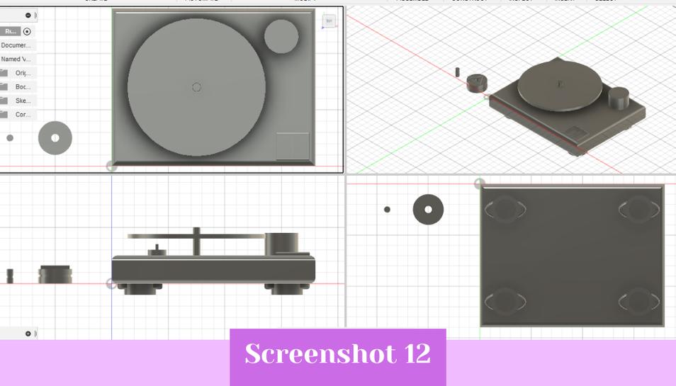
 I also applied appearances to the models as they looked a little incomplete without (screenshot 12).
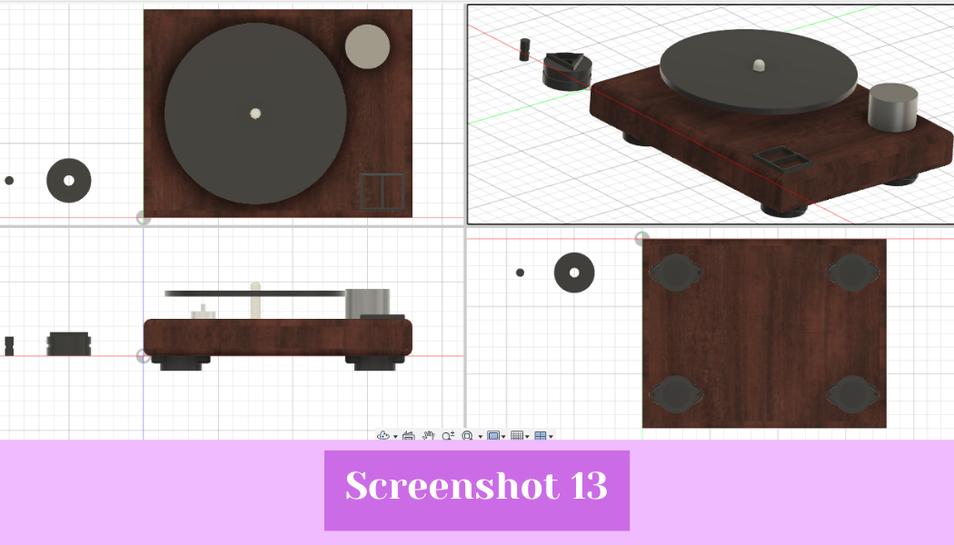
 I did this by hitting shortcut letter “a” and then I dragged out a wood appearance for the base block, and black or white plastic appearance for everything else (screenshot 13). With that I completed my model, and saved it as a .svg which you can download using the link below.
CorelDraw
I have been using CorelDraw since taking my first engineering class that Latin. This translates to about 4 year of experience using the program. I feel pretty comfortable using CorelDraw and because of this I wanted to design a first version of my record player platter in the program that would snap to my platter holder design I made in Fusion 360 (see above).
Designing in CorelDraw
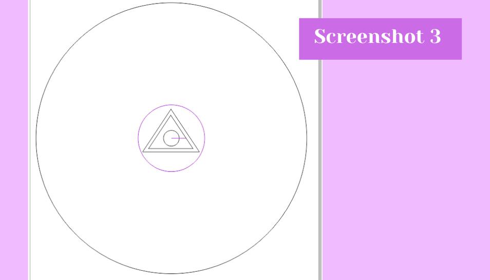
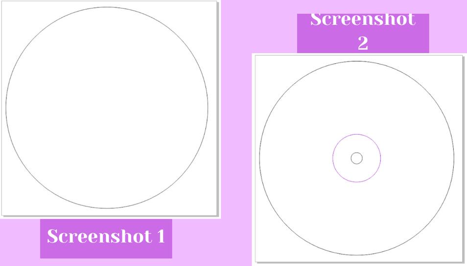
I decided to make a first version of my platter for my record player in Corel. I think I will end up milling the platter so this design could probably be used for both that and to laser cut a test version of it before I commit to using the ShopBot and making the final version. I began by creating a new document and changing the document page size and the document units. I changed it to 13 inches for the width and height as this was slightly larger than the design I want to make. I then used the circle tool from the left hand shapes menu to draw out a random picture. To make the circle my desired measurements I went up to the top bar in CorelDraw and changed the size of the circle in the left hand length and width boxes rather than trying to drag out the circle to how big I wanted it. I changed the dimensions 12.2” inches because a standard 33.3 RPM record is 12” inches but sometimes 10” inches (screenshot 1). Then I added a second circle and changed its dimensions to .026” inches for both the length and width. This circle will be for the center rod that will hold the platter and record and allow them to spin. I measured the diameter of the center rod of my record player at home using calipers and it came out to 7 mm (screenshot 2) so I made that the diameter of the center hole. Next, I added in a purple guideline for adding my triangle.
 I added the 3” inch circle that the triangle holder would be attached to per my Fusion 360 design. The circle I snapped to the middle of the other two circles. Next, I added a polygon from the left side bar. The polygon automatically sets to have 4 side, which is not ideal for making a triangle so I changed the number of side in the top bar from 4 to 3. Next, I referred to my Fusion 360 design for the triangle and used the measure tool in Fusion 360 to make the triangle in CorelDraw. I found the length of the base of the triangle, and then I also found the altitude of the triangle. I took these two measurements and put them in for the width and length of the triangle to get a triangle that was congruent to the triangle in Fusion 360. I did this for both the smaller and larger triangles. Next, I double checked this by drawing a purple guideline from the center of all of the circles I made to the edge of both triangles making sure that in both Corel and Fusion they were the same distance apart, further confirming that they are congruent and placed correctly. To finish off my design I made all black lines hairline so that if cut on the laser cutter, they would vector rather than raster. (Screenshot 3) You can download the file using the link below.