8. Electronics Production
This week I designed and milled a final project PCB.
Group Work
This week I cut a test strip on a milling machine with a 0.005” engraving bit and my group members used other sized bits. You can see my work along with my group member’s Dariyah Strachan, Dylan Ferro, Stuart Christhilf, and David Tian work on the Charlotte Latin Fab Lab site for student group B.
Making a PCB
Designing the PCB
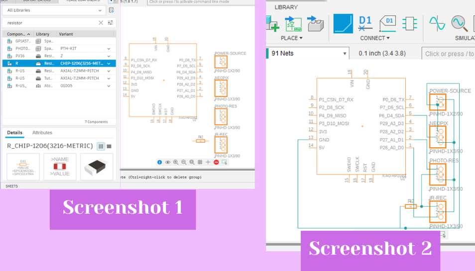
I decided to use Eagle in Fusion 360 to create my board for my final project. I went in and created a new electronics design from the file tab. I started by dragging out all schematic footprints I would need by searching for them in the left side picker and selecting on each component I wanted (screenshot 1). They are as follows:
- 1 SEEED Xiao RP2040
- 3 1x3 header pins
- 1 1x2 header pin
- 1 1206 SMD resistors
With all of the components dragged out, I began using the net tool from the top bar to connect the components together (screenshot 2). I used the net tool and clicked on each pin that I wanted to connect and it made a line between the selected pins; I did this for everything I wanted to connect (screenshot 2).
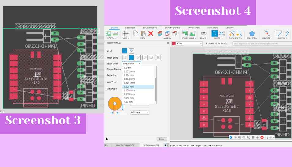
 With everything netted I switched to the PCB editor by clicking on the PCB icon in the top left hand corner of the schematic editor. This opened up the PCB workspace and I began by arranging all of my components on the board and by clicking on and dragging in the boundaries of the PCB workspace (screenshot 3). My goal was to have a very small PCB because everything needed to fit into the middle of my lamp, and the board was nearly 2” x 2” so I think this was very successful. Next, I used the manual route tool from the top bar to connect each pad of the footprints together (screenshot 4, blue box). I upped the trace width to 20 mil (screenshot 4, left side) and then clicked on each pad and drew the traces (screenshot 4).
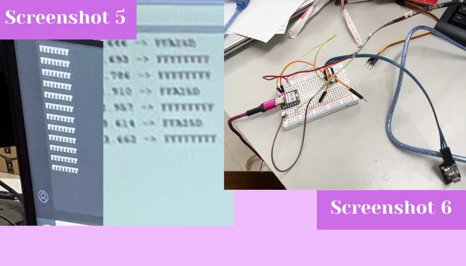
 With everything routed and traces made (screenshot 5), I exported my file as a Gerber by going to the manufacture tab and clicking on that option (screenshot 6).
- Board Schematic .sch
- PCB File .brd
- Board Top .png
- Board Profile .png
- Board Top and Profile .gbr (gerber)
Milling the PCB
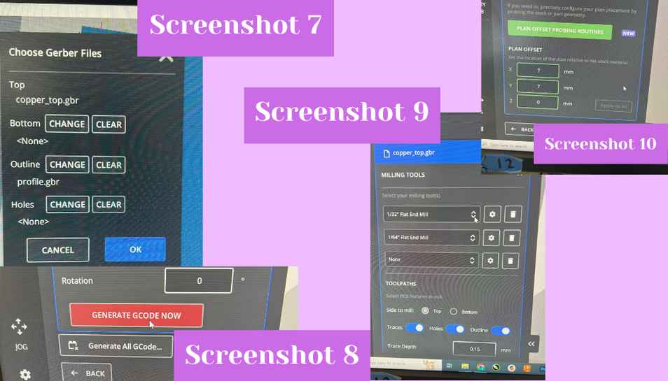
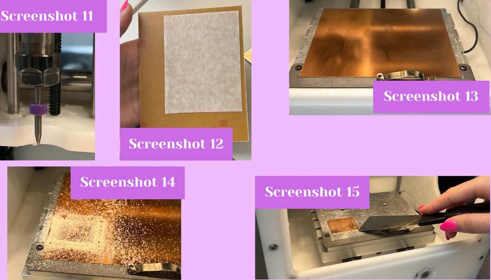
I downloaded my file from our lab’s Google Drive and then went into the Bantam milling software to mill the board. I used a large piece of Nitto tape to affix a piece of FR1 to the mill bed (screenshots 12 and 13). I stuck with the preset file setup for dimensions and thickness for FR1 boards and uploaded my Gerber files for the copper top and the profile (screenshot 7). I then picked the bits I was going to use from the drop downs (screenshot 9) and then I used the “generate GCODE now” button to turn the Gerber file into GCODE that the machine could read (screenshot 8). I then input the plan offset which is how far from the origin point you want your job to mill, so for example setting it to 0, 0 might be a bad idea because you might mill too close to the edge, and placing a design in the center of a new FR1 board would be wasteful, so I set mine slightly off the corner edge to 7, 7 (screenshot 10).
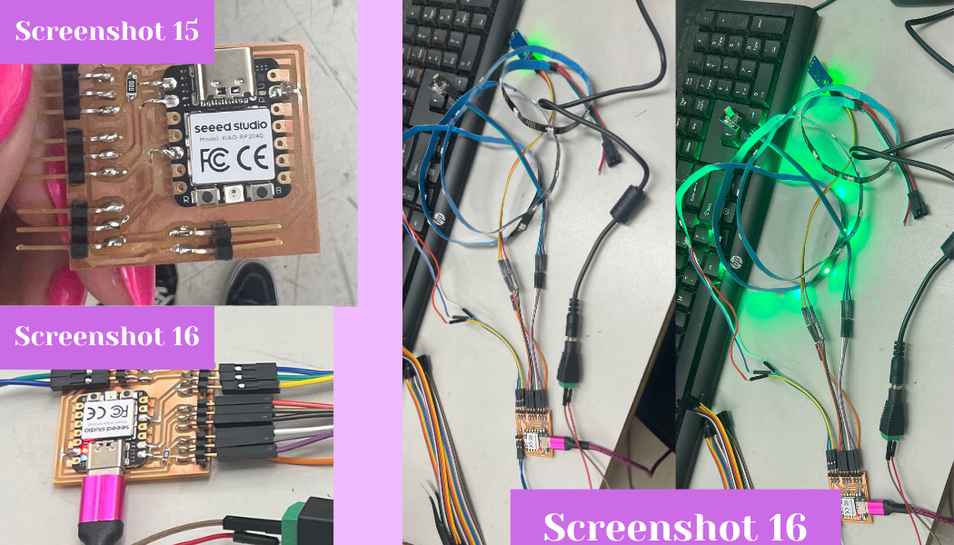
 From there I installed a 1/64” two flute up cut flat endmill bit and then milled the file (screenshot 11). The job stopped about halfway through to change bits to the 1/32” two flute up cut flat endmill for the edge cut and larger areas of the design. After it was done milling (screenshot 14) I pried the FR1 up from the bed using a putty knife (screenshot 15), and then I soldered my components to the board. The components list is as follows:
- 1 SEEED Xiao RP2040
- 3 group of three surface mount header pins
- 1 group of two surface mount header pins
- 1 0 ohm SMD resistor
From there I installed a 1/64” two flute up cut flat endmill bit and then milled the file (screenshot 11). The job stopped about halfway through to change bits to the 1/32” two flute up cut flat endmill for the edge cut and larger areas of the design. After it was done milling (screenshot 14) I pried the FR1 up from the bed using a putty knife (screenshot 15), and then I soldered my components to the board. The components list is as follows:
- 1 SEEED Xiao RP2040
- 3 group of three surface mount header pins
- 1 group of two surface mount header pins
- 1 0 ohm SMD resistor
Testing the PCB board
With everything soldered onto my board (and no traces ripped!!), I proceeded with testing the board to ensure it worked (screenshot 15, picture below). I plugged all of my electronic inputs and outputs into the header pins, and then I uploaded my final combined code onto the SEEED Xiao RP2040 (screenshot 16, left). I then plugged in the external power source to the board, and into the wall. Finally, I plugged in the USB-C to a brick and then into the wall. I then used the remote and the NeoPixel turned on, changed brightness, and changed color! (screenshots 16, right side)