5. 3D Printing and Scanning
This week I worked on designing an object that cannot be made through subtractive manufacturing and 3D scanning an object both to 3D print on a PRUSA MINI+ printer.
Group Work
We tested many of the features of the Prusa MINI+ 3D printer and then compared it to the features of the Formlabs 3+ SLA Printer and the Bambu Labs X-1 Carbon Combo 3D Printer which the other two groups analyzed. You can see my work on surface finish analysis along with my group member’s Dariyah Strachan, Dylan Ferro, Stuart Christhilf, and David Tian work on the Charlotte Latin Fab Lab site for student group B.
Designing My Non-Subtractive Object
I picked my object at the recommendation of a friend from school who told Dariyah Strachan that she should do the item but Dariyah had already picked an infinity cube so she told me about the object that the friend had reccomended. The object I picked is an interlocking set of mobius rings. I began by switching into the ‘surface’ tab along the top bar and in there I clicked the create a sketch button and started my design by making two three inch lines and a five inch curve and I snapped the middle of the lines to the end points of the long line using the midpoint constraint (screenshot 1). From there I created a three point arc along the the right three inch line (screenshot 2).
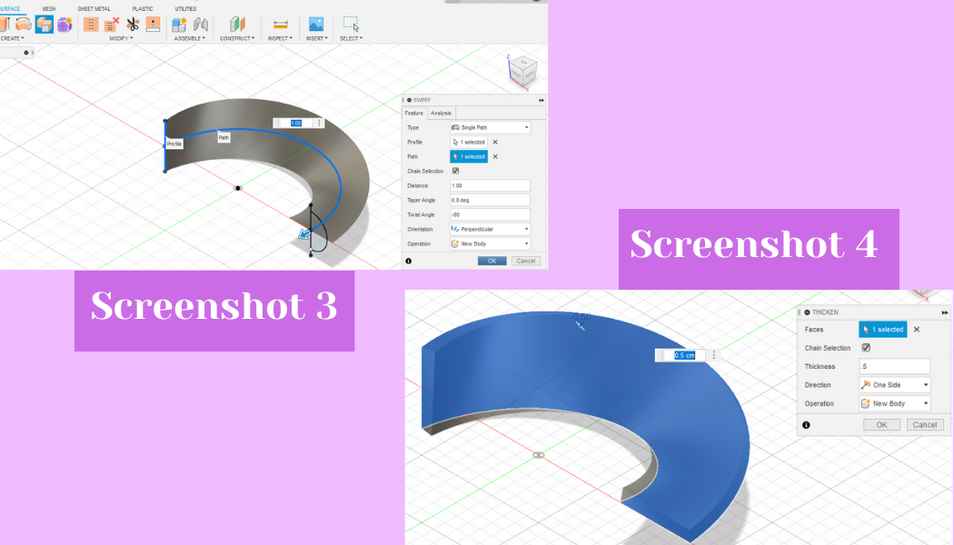
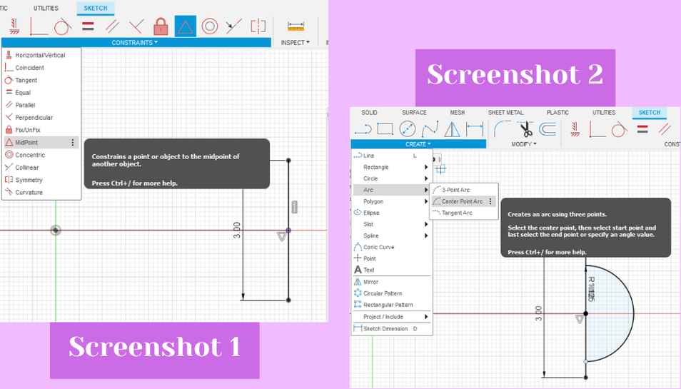 Next, I used the sweep tool from the create drop down menu to sweep the left three inch line along the curve and I also changed the ‘twist angle’ to -90 degrees (screenshot 3). From there I used the thicken tool from the drop down menu to give the sweep depth. I made the thickness 0.5 in (screenshot 4).
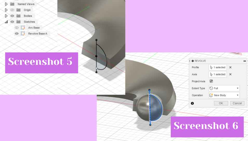
 To make the next step I turned on the sketch with the three inch lines and the half curve (screenshot 5). I then changed the workspace to ‘solid’ Using the sketch with the semicircle on the three inch right line, I used the revolve tool from the drop down menu to revolve the semicircle around the line (screenshot 6).
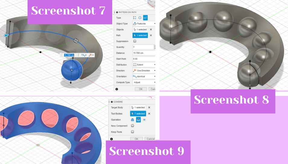
 To duplicate that circle around the half twist ring I used the pattern on path tool from the create drop down. The object was the sphere I had just made, and the path was the twist line (screenshot 7). I made 7 copies of the sphere (screenshot 8). To cut out the circles from the half twist ring I used the combine tool from the modify drop down. I selected the half twist ring as the target body and the tool bodies as the spheres. I also changed the operation to cut and clicked ok to cut out the ring (screenshot 9).
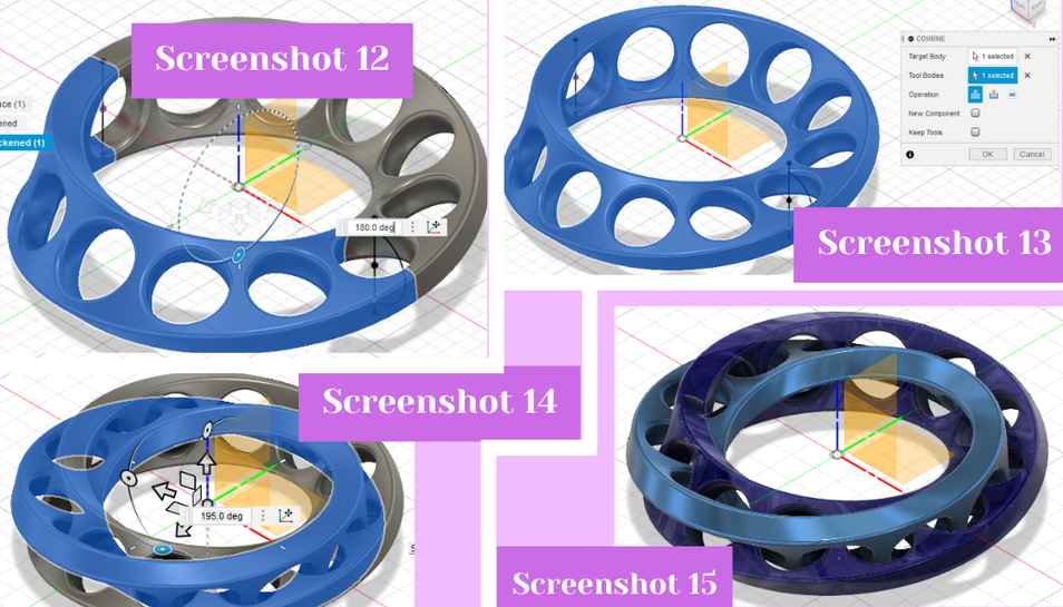
 Next, to make all of the edges smoother I filleted all of the edges in the half twist ring 0.15 (screenshot 10). With the half ring done, I now only had to copy/move the half ring three times. To do that I used the shortcut letter ‘m’ to activate the move/copy tool. In the dialog box that opens I moved the pivot point to the origin of the plane space (screenshot 11), then I clicked the make a copy box, and then I rotated it using the circular handles 180 degrees (screenshot 12).
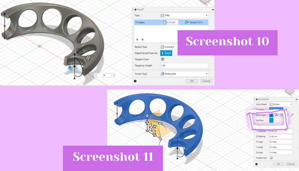 To combine the two halves I used the combine tool from the modify drop down (screenshot 13). To make two interlocking mobius rings I needed to copy the ring I had just made via combining. I used the shortcut letter to open the move/copy dialog and in the box I moved the pivot point to the origin, then clicked create a copy, and then I used the handles to rotate the copy 195 degrees so that the circular cutouts were inside one another (screenshot 14). With that my design was done but for aesthetic reasons I wanted each ring to be a different colors so I used shortcut letter ‘a’ and dragged out sapphire and blue anodized aluminum on to each respective ring (screenshot 15). My file can be downloaded for 3D printing below.
.3mf File Download of Interlocking Mobius Rings
.f3d File Download of Interlocking Mobius Rings
.stl File Download of Interlocking Mobius Rings
Printing My Non-Subtractive Object
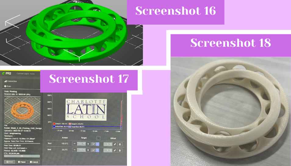
To print my object I uploaded the .stl to Prusa Slicer and I scaled it up a little but because it was a little too small (screenshot 16). I changed the printer type to the Prusa iMK3+ because the that was one of the only printers available with enough filament left on the role to comfortably print. I then generated supports from the build plate only and changed the infill to 10%. Once it sliced, I downloaded the GCODE, and then uploaded the file to our Fab Lab’s printer specific website for printer PR2 (screenshot 17). After cleaning the print bed off with some alcohol and a paper towel, I hit the print button in the website and left the printer to print. I took about 6 1/2 hours, so the next morning I came in to the lab with the print done. It looked good, but it did have a lot of supports. I personally hate removing supports because they are never easy to get off, but I had a few friends in my class that love removing them so I let them take the supports off. Shout out to Dariyah, Maya, and Sydney!! To remove them they used a pair of old crusty wire cutters to pry the supports off and then for the finer parts they just picked them off by hand. This left me with a really clean and nice looking set of interlocking mobius rings (screenshot 18).
3D Scanning An Object
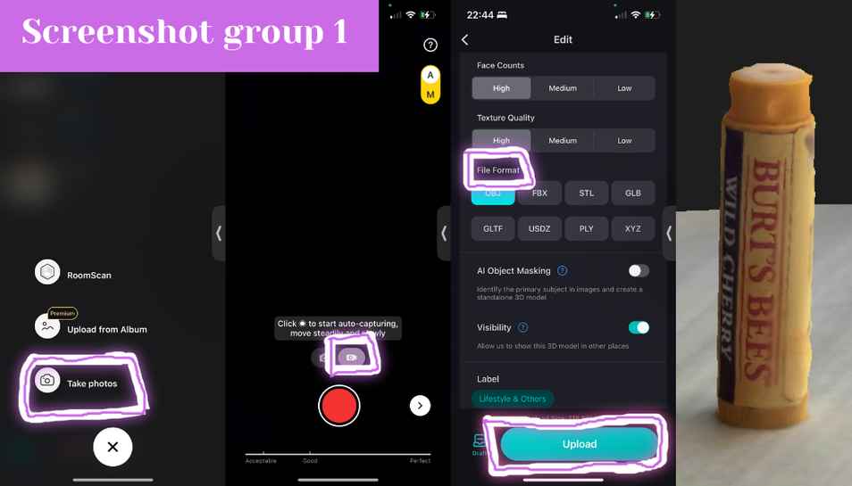
To 3D scan my object I searched up 3D scanner in the Apple App Store and picked the one I liked the look of best. I chose KIRI Engine which turned out to be a popular pick with the Fab Academy students at my lab. KIRI is simple-ish to use. I scanned my object by hitting the plus sign at the bottom of the landing page and then hit the take photos button (screenshot group 1 picture 1). It then brings up your camera and you can either take 70 photos the traditional way or you can take a video and it will take the photos for you; I chose video (screenshot group 1 picture 2). The basic idea of scanning with this app and in general is that you get a non-shiny, reflective, or transparent object, set it on a surface, and then go around it to capture the photos. So to get the images I move my phone around my object. The object I chose was an uncapped tube of wild cherry Burt’s Bees ChapStick because I was out of ideas and just decided to pick something from around me. After I took all the photo I hit the right pointing arrow to move onto the next step of the process. In the edit page which popped up, I left all settings the same but you can change the file type if needed, I then hit upload (screenshot group 1 picture 3). Next, I waited about 15 minutes for it to generate the object and when it did it opened what you can see in the last photo of the screenshot group (screenshot group 1 picture 4). You can download the file it made below.
3D Scanning .obj File- Chapstick words!!
3D Printing My Scanned Object
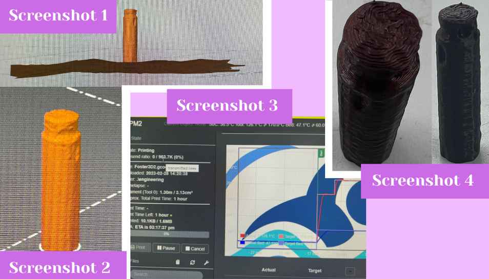
To print it, I downloaded the file and opened it in Prusa slicer (screenshot 1). Then I scaled up the ChapStick by a lot because it was tiny when first imported; I also moved the desk below the plane so it wouldn’t print in the final (screenshot 2). I used all of the normal settings but changed infill from 20% to 10%. I then downloaded the GCODE and opened the Lab’s printer specific website for the 2nd Prusa Mini we have. I uploaded my file in the website and after wiping the bed off with alcohol, I hit print in the website (screenshot 3). After about 1 hour I was left with, in my opinion, one janky looking replica of my ChapStick (screenshot 4).
Thoughts on 3D Scanning
Personally, based off of this experience, I am not a fan of 3D scanning. It might just have been the app I used but the resulting 3D model from the object was very inconsistent in quality. In one spot of the 3D ChapStick there is a dent where it should be smooth. Also the app, though easy, was also a bit of a hassle to move around the object for several minutes while it took pictures. For the time I spent, I felt the result was not worth it. Personally, I would rather just measure an object and design it myself in a CAD program because it would look far better than the scanner would. 2/5 stars.