Final Project
Research
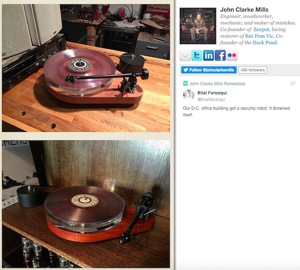
I found a open-source record player that was referenced on several pages and all linked to the same website (http://turntable.develop.vodka/), but the site was inactive. Kai informed me about archive.org, where you can go and look at past versions of sites that have been taken down. I was then able to access the page through archive.org.
The page linked to a Github page, and I downloaded his designs. It did not include a parts list, but it was a starting point. He used through hole components, but I will not, generally. I may use some if they are available in our Lab’s inventory so that I don’t have to order components when we already have some.
I also got in contact with the maker of the turntable, Zach Dicklin, and he gave me links to V1 and V2 his record player.
Stepper Motors in General / Microstepping
I wanted to figure out if I could use the stepper motor board that I made in Week 12, so I tried to learn about microstepping here. I also found that I didn’t know much about stepper motors and how they function in general, so I referenced this page.
Microstepping… - Moves the stator flux of the stepper more smoothly - Causes less vibration and possibly noiseless stepping -
I learned that stepper motors…
- Convert electrical pulses into discrete mechanical movements that move the motor some fraction of a full rotation
- Aren’t easy to operate at extremely high speeds
- Are synchronus electrical motors
- Have a stable stop position that’s in sync with the stator flux
DC Motors
I was concerned that I wouldn’t be able to use a stepper motor because I might require a higher speed than what it can perform. Also, whenever I used the steppers, it would get quite hot decently quickly. I wanted a motor that would not get as hot, so I watched this video on DC motors. A lot of the sites I see online where people made their own record players reference that they used DC motors.
Here’s what I learned:
- There are shunt motors (in parallel) and series motors (in series)
- Shunt motors have a low starting torque but can maintain constant speed regardless of load
- Speed drops with larger load/torque
After doing research on both stepper motors and DC motors, I decided to just stick with the stepper motor board that I made in Week 16. It’s identical to the one I made in Week 12 except for the fact that the
Stepper
I eventually decided to just use the stepper motor/board that I’ve been using since Outputs Week / Week 12. I did some research on pulley ratios and used this pulley calculator site to figure out what I needed to do.
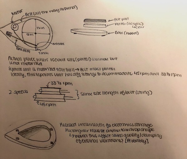
My record player at home has a motor that only rotates at one speed. However, it has a belt system and two different sized pulleys that connect to the platter of the record via a belt.
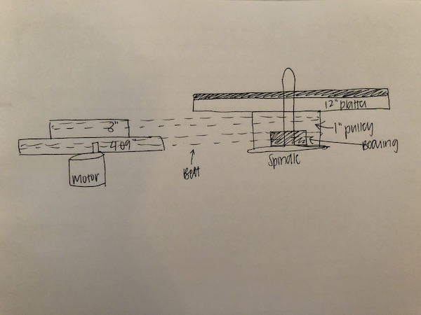
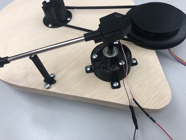
The motor on my record player rotates at about 1800 rpm because the smaller pulleys are rotating the larger, 12” record platter. I did the opposite, where the smaller pulley will be underneath the record platter so that my motor does not have to go that fast. I wanted to run my motor at one speed for both the 33 rpm and 45 rpm settings for the record. To accomplish this, I used a belt system with different sized pulleys. Underneath my record, I have a 1” diameter circle. My concentric pulleys that control the different speeds have different diameters (3” and 4.09”), corresponding to 33 rpm and 45 rpm respectively. Here’s a drawing that explains my system:
BOM
Scroll right to see the entire spreadsheet
License
As described in Week 19, I am using a Creative Commons Attribution Non Commercial license (or **Attribution-NonCommercial-ShareAlike 4.0 International license). I described why I chose this specific license in Week 19.
Design
Planning during Weeks of Fab
Here are the drawings I made in Week 1, and the ones below that are ones that I drew inspiration from. I am a big fan of the teardrop shape that is shown, so I wanted that to be part of my final project.
In Week 2, I designed this record player to show what I roughly wanted to do for my final project.
My design eventually changed because my pulley system needed to be at the same level as the platter. It could not be on the lower level as shown in my original CAD design.
3D Printed parts
I designed my 3D prints in Fusion 360 using the skills I used in Week 3. I designed everything with screw holes so that, for my base, I would just have to cut out a simple 2D toolpath. I descibe the base creating process later.
Test Prints
I ran multiple test prints for tolerance and fit on the 3D printer. I needed to make sure that my final prints would fit together properly, so I spent a lot of time just making test prints. Of course, when I was designing these files, I used calipers to get as accurate of a measurement as possible, but 3D printing isn’t exact because the plastic melts. Because of this, what is printed is a little bit bigger than what was designed.
I made test prints for the following, and the measurements that worked were used in the design in parentheses.
- Fit around the bearing (1” pulley)
- Fit inside the bearing (spindle)
- Spindle diameter (spindle)
- Top of the 1” pulley (1” pulley)
- Fit around the casted foot (Foot)
- Fit around stepper rotating piece
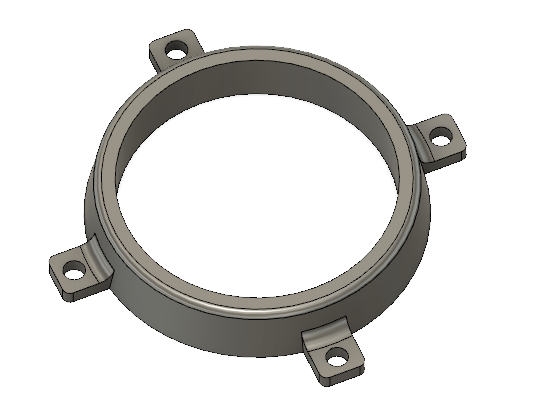
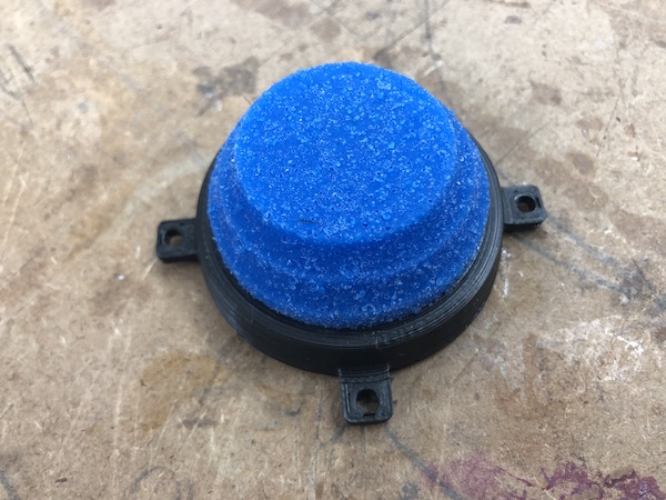
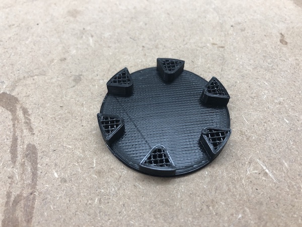
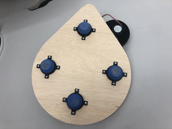
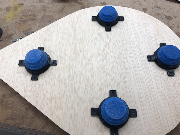
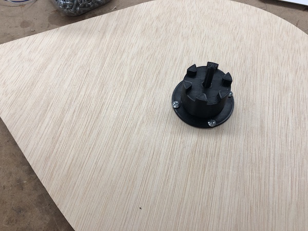
Foot Holder
I already made feet for my record player in Molding and Casting Week / Week 10. I needed some way to attach these feet to the bottom of my record player; I didn’t just want to glue it to the bottom. I figured that if I 3D printed something that was slightly smaller than the actual diameter of the foot, it would hold the casted foot. The foot is made of a silicone, so it just holds it in place. Then, when it comes to putting the foot into the holder, it just squeezes in there because it’s a soft and somewhat flexible material (silicone).
I had two iterations of this design. Here’s the first design:
I included screw holes, but I was concerned that the rectangle around it wasn’t large enough and that when I screwed it to the base of the record player, the they might break. They were very very thin. So, I made another iteration in which the rectangles were larger:
Final:
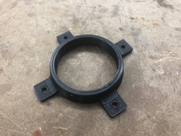
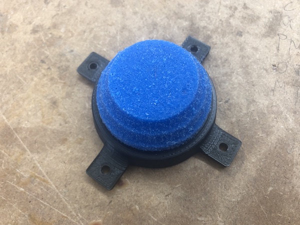
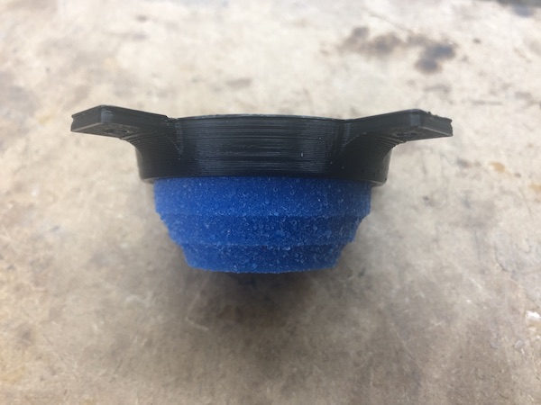
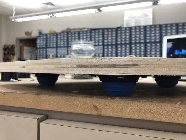
They fit on the feet really nicely.
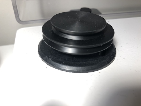
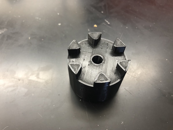
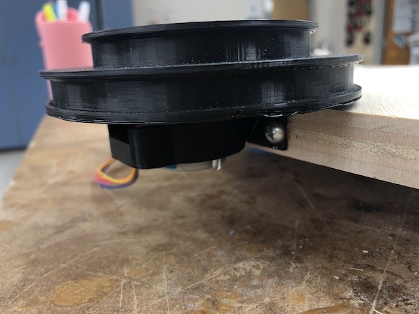
Large Pulley
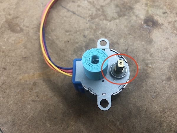
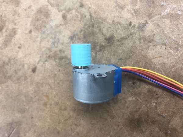
I call these my “pulley pancakes” because they’re just cylinders with different diameters. As described above in the Stepper section, one has a diameter of 3” and the other has a diameter of 4.09”. Underneath, it has a hole for the piece that rotates on the stepper. I did a test print for this, just to make sure that the piece would fit perfectly onto this rotating piece.
Rotating piece and test piece:
Final:
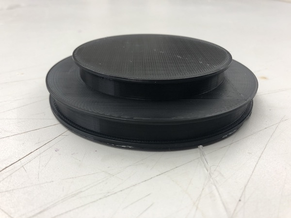
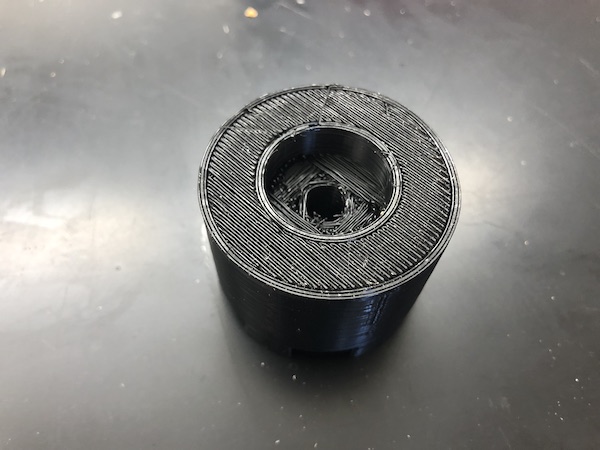
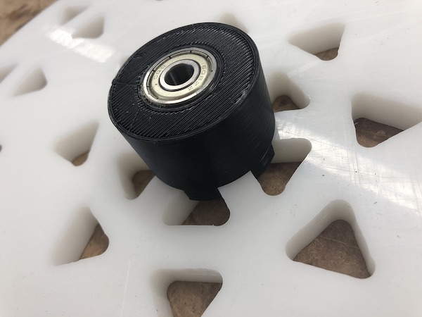
Small Pulley
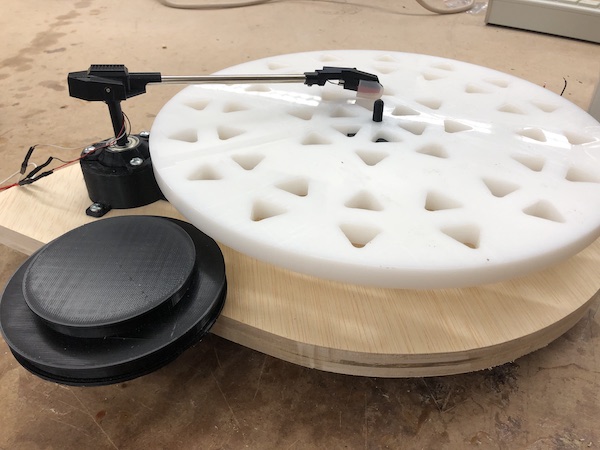
This piece goes underneath the platter and has the bearing inside it toward the bottom. It was especially difficult to design and required several 3D print tests. It took three tries to get the right measurements for the top of the pulley. I wanted it to fit into the spaces in the design of the platter. Then, I also made test prints to make sure that the bearing would fit extremely snugly into it.
Test print of top:
I ended these test prints before they were done because I only needed it tall enough to be able to see if it would fit in with the platter.
Test print around bearing:
Final CAD:
Final:
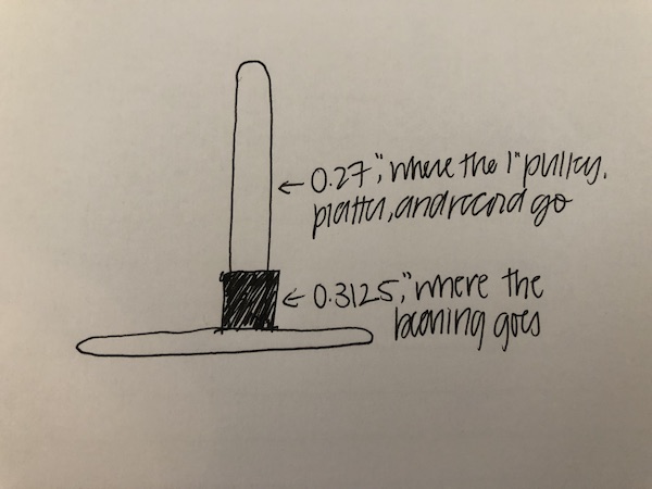
Spindle
This piece is critical because it is what everything rotates around, so I needed to make sure that it had the correct diameter. It needed to be thin enough to fit through the hole in the record / platter / pulley / bearing, but it couldn’t be so thin that everything can wobble around. I did some test prints to figure out the measurements I needed. Going from left to right, the diameters are 0.25, 0.27, and 0.3125 inches:
I needed the lower part of the spindle to be thicker because the bearing should sit there. In fact, I wanted it so that the fit of the spindle and inside of the bearing was so tight that the interior of the bearing wouldn’t rotate at all. Only the outside of the bearing should rotate, and the interior stays stationary.
When I printed the three spindle sizes, the print failed halfway through (the PLA stopped extruding). However, the cylinders were still tall enough that I could test which diameter worked best for what.
I found that the 0.3125” diameter worked really well for inside the bearing.
So, I used the 0.3125” measurement for the spindle inside the bearing. For all other parts, I used 0.27” diameter.
Here’s how it turned out:
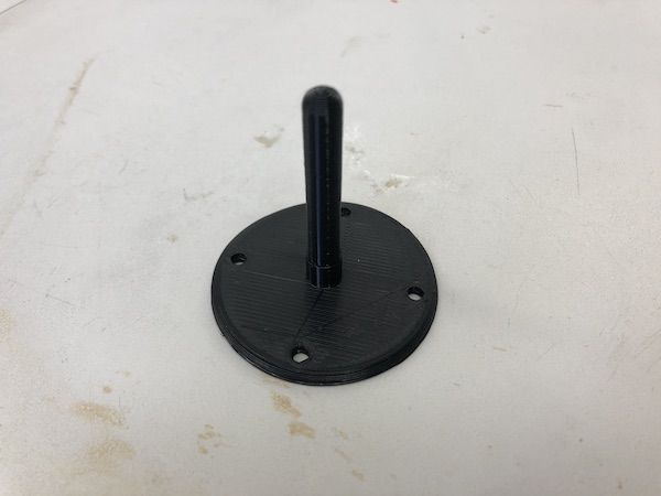
Notice the difference in diameter on the spindle.
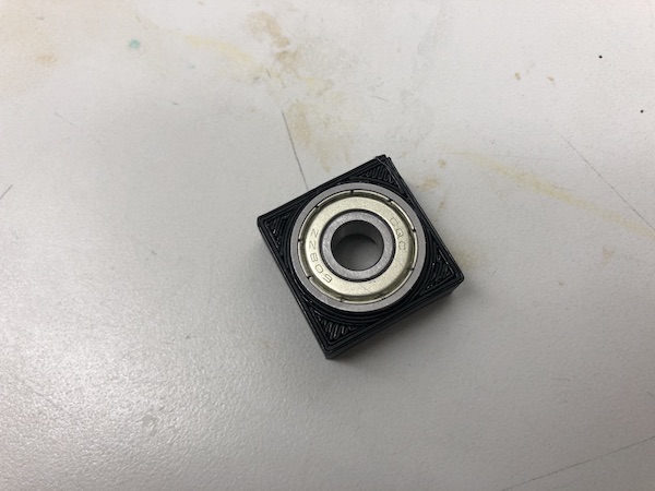
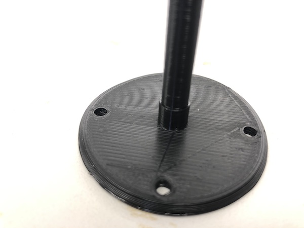
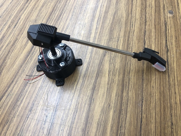
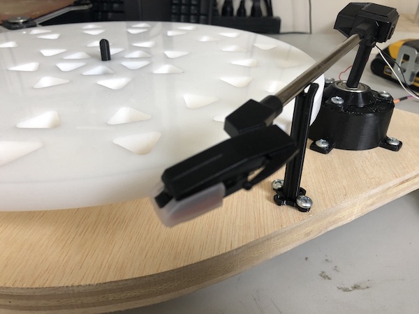
Tonearm Base
I knew that I needed my tonearm to be able to move horizontally, so I decided to use a bearing at the base of my tonearm. I used the measurements that I found worked when I was making the 1” pulley for the area surrounding the bearing.
Final product:


Here’s a video of the rotation of the tonearm in the bearing base:
I saw that I would need my tonearm to be taller than just putting it on top of the base. In other words, when I put the tonearm just on the base, it was far too short to actually reach the record that would be on the platter. So, I had to create a booster so that the tonearm would be taller. The new booster is 1 inch tall and has holes for the screw holes of the tonearm base to screw into. It also has an extra hole for the tonearm’s wires to pass through (cable management).
Final:
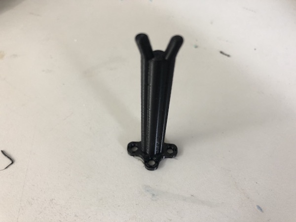
Tonearm Stand
All record players have a place where the tonearm rests. I designed a very simple one for my tonearm, including 4 screw holes. In the end, I only used two of these screw holes. I made sure that it was the correct height.
All of the 3D printed parts for the tonearm:
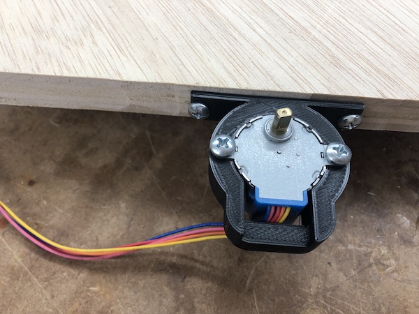
Stepper Motor Holder
Originally, I was really confused as to where I would put my stepper motor. In my original Fusion 360 design I created in Week 3, I had the motor on a lower level of the base. I realized that this would not work because I needed the large pulley to be at the same level as the small pulley so that the belt would just travel horizontally and not be slanted in any way. This drawing shows what I mean:
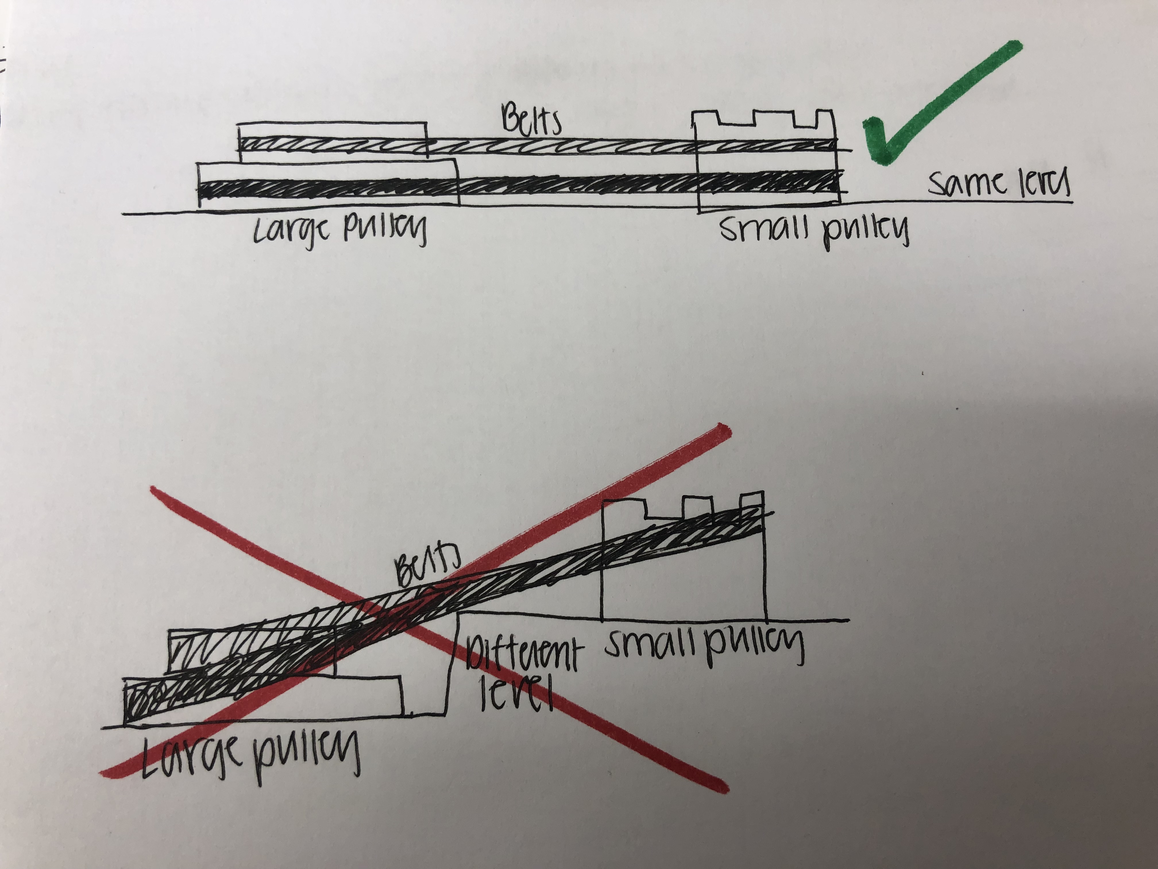
The diagram shows two belts on there, but I would never put two belts on simultaneously. They’re just there to prove the point that having the pulleys at different levels just does not work.
Eventually, I realized that I could stick the stepper motor on the side so that the large pulley (on top of the stepper motor) could be at the same level as the small 1” pulley. So, I designed a holder that has screw holes on the side of it to screw it onto the side of the wooden base. I included


CNC
Platter
I originally wanted to cut my platter out of half inch acrylic (like my record player has), but I saw that we had this HDPE at the lab that I could use. It was 0.5 inches, so it was perfect. I saw that it was quite heavy, so I was concerned that I’d be overloading my motor. To lessen the load a bit, I decided to create a little design on my platter. I designed several different platters because I couldn’t decide which design I thought was the coolest. Later, I realized that some of my designs wouldn’t work because they would create uneven weight distribution and the platter to wobble. When I designed what I eventuallly ended up sticking with (shown below), I made sure to always use an even amount of triangles so that the platter would have the same amount of cutouts all around.
Following basically the same procedure from Week 8/Computer Controlled Machining, I created a .sbp toolpath in Aspire and milled out the platter on the ShopBot.
I created two separate files for the triangles in the design and the outlined circle. I cut the triangles first.
Making the .sbp
I made the .sbp in Aspire, and I describe the process in more depth in Week 8.
I put my .svg of the file into Aspire and moved it around to where I wanted it on the material.
I went to the Toolpath section on the left side of Aspire and selected the outline circle (that’s what I made first). My settings are shown below. For the outside cut, I used Outside/Right because it’s an outline. For the triangles, I used Inside/Left, but the settings are the same for everything else for the triangle sbp.
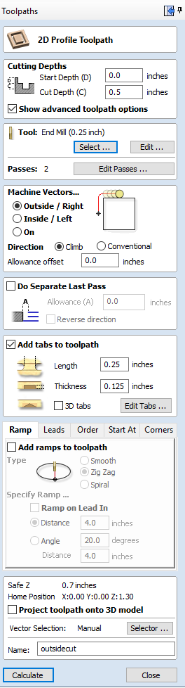
Underneath the Add tabs to toolpath, I added “tabs”. This just means that the machine will leave little tabs of material on the last pass instead of milling everything out so that the material doesn’t move once most of the milled material is gone. I added five tabs.
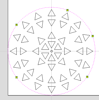
Here’s the preview of what it will look like from Aspire:
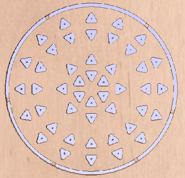
Even when I designed the platter, I knew that the triangles in the platter wouldn’t have sharp corners since I was using an 0.25in bit. This was the goal (to have rounded corners).
I didn’t have to post process this platter at all, which was really nice.
Base
Since I designed screw holes on all of the 3D prints, I didn’t need to use 3D milling for my base. I created my design Fusion.
Again, I used Aspire to design the toolpaths and cut it on the ShopBot.
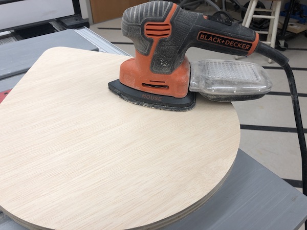
Since I cut it out of wood, I had to post process the rough edges of the wood. I sanded the edges, as shown below, and I also used the power sander to sand the surfaces of the base.
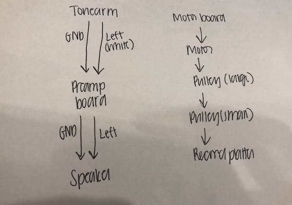
Electronics
Flow of electronics, explained in a diagram:
Pre-Amp
To understand the electronics that Zach used in his schematic a little bit better, I looked into the datasheets a bit.
LD1117 Datasheet - LD1117AV33 - Fixed output voltage of 3.3 V - Input voltage up to 10 V - Output current up to 1 A
Reading some of the datasheet was helpful to understand why Zach did what he did. I read that “the gain is internally set to 20 to keep external part count low, but the addition of an external resistor and capacitor between pins 1 and 8 will increase the gain to any value from 20 to 200.” There is a resistor and capacitor between pins 1 and 8 in his schematic, strengthening the amplification of the signal.
The datasheet kept on mentioning “quiescence.” I didn’t know what it meant, so I looked it up and found that “for an electronic circuit, a quiet state in which the circuit is driving no load and its inputs are not cycling. Most commonly used for the specification “quiescent current,” the current consumed by a circuit when it in a quiescent state” here.
Amp Board V1.1
Originally, I basically copied Zach’s exact schematic except for the motor and autostop functions (since I already had a board for my motor). I used surface mount components (whereas Zach used all through hole components) where I could, but we already had some of the through hole components stocked at the lab and I decided to just use those instead of ordering surface mounts. The schematic I made was the same except for the fact that I was using some slightly different components (like surface mount vs his through hole components). I describe the full process by which I design my boards in Week 7.
I crossed out what I didn’t use for my schematic:
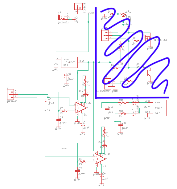
I also used the Sparkfun Capacitor library, available on Eagle. It was super helpful because I didn’t have to go and find every single footprint online (from SnapEDA or a similar site) like I normally do.
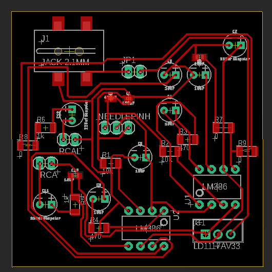
My schematic and board:
Don’t download my Eagle files, they don’t work.
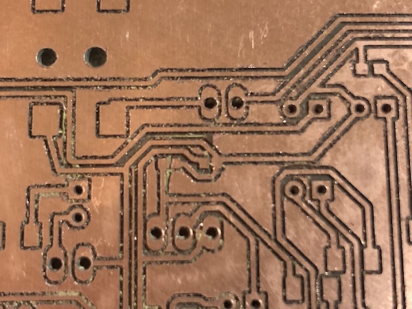
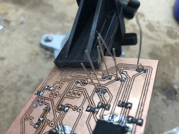
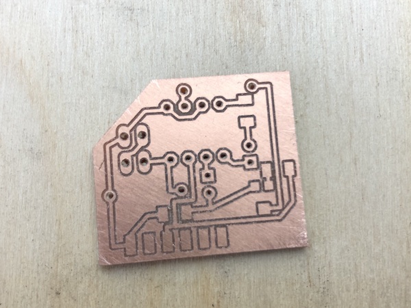
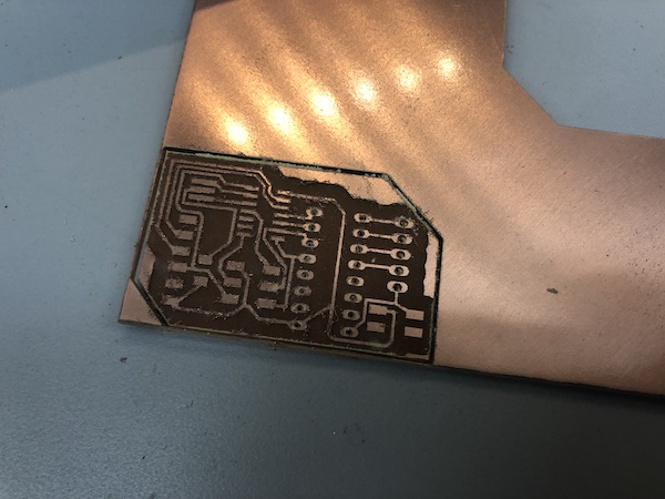
Milled board:
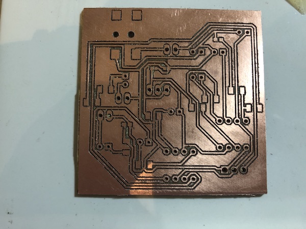
I had some really tiny components for this board. It was so small that the 1/64th bit on the Othermill couldn’t even mill between the two pads of it.
I didn’t realize that they were so small when I ordered them. The components that were really small were the 470nf and the 10nf capacitors.
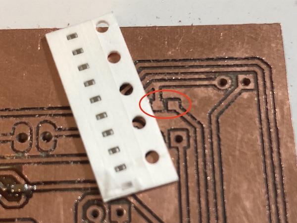
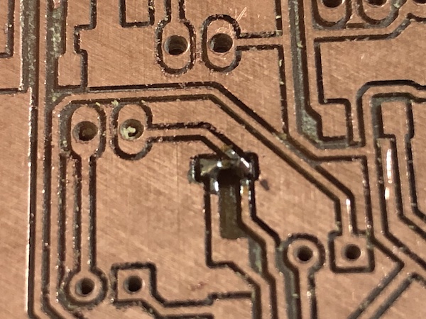
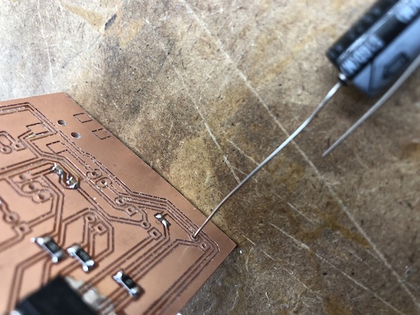
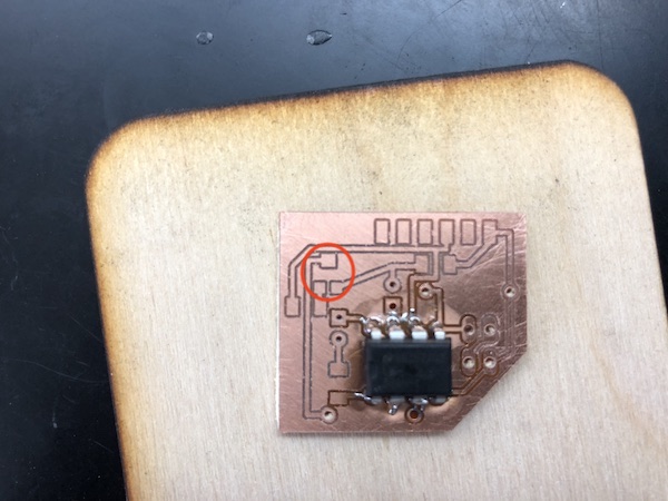
When I saw that the Othermill couldn’t mill the space between the capacitors’ pads, I used an X-acto knife to cut it.
It wasn’t as difficult to solder as I would imagine it to be. Certainly, it required some steady hands, but it wasn’t super bad. I did, however, end up accidentally losing two of the tiny capacitors because I breathed out and blew them away. It’s a good thing I ordered triple of all of my electronic components.
When I got to soldering the 10nf capacitors, I found that my pads were much too big for the components I actually had. This can be attributed to the fact that I used the Sparkfun library and that I was using a different part than what they have a footprint for on the library. Here’s the size comparison, not soldered and soldered:
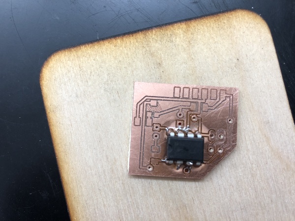
As seen in my schematic, I just used the same footprint for the 220 uf capacitors as the 10 uf capacitors. When it came to soldering, I realized that that was not the move. I couldn’t put the leg of the 220uf capacitor into the hole.
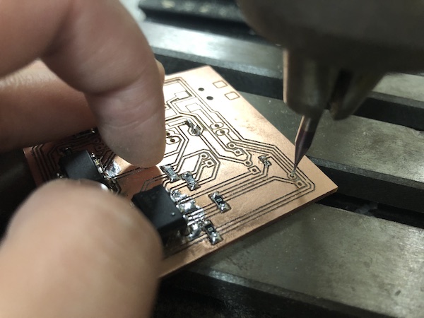
So, I had to use a 1/32nd bit and the drill press to make the holes bigger.
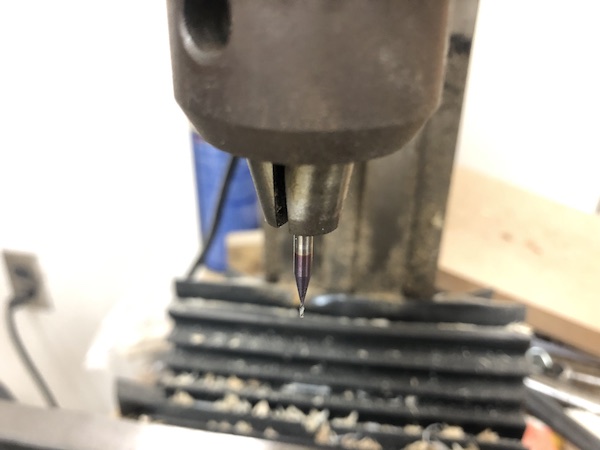
When the machine was off, I took the bit and lowered it until it was right above the hole where I wanted it to go. I made sure to keep my board in that same position as I brought the bit back up and started the machine. I also made sure to put the hole I wanted to drill above an open space in the base, as shown below. Otherwise, the bit would hit the bottom of the drill press’s base and possibly damage it.
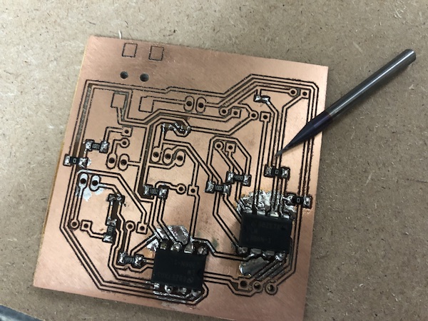
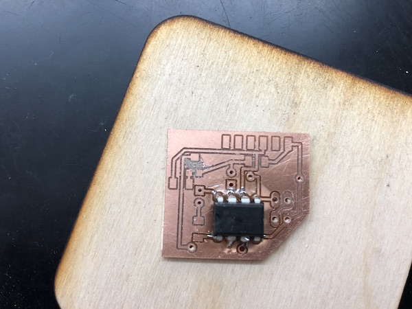
Once I made the holes bigger, I was easily able to put the leg of the capacitor into the hole and continue soldering. I soldered the capacitors onto the other side of the PCB, just making sure that I had them oriented properly.
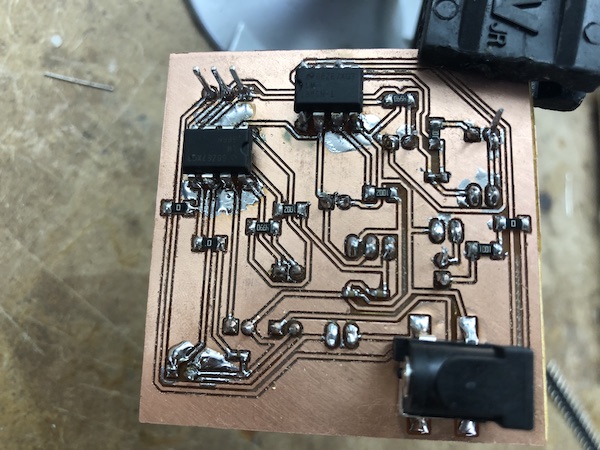
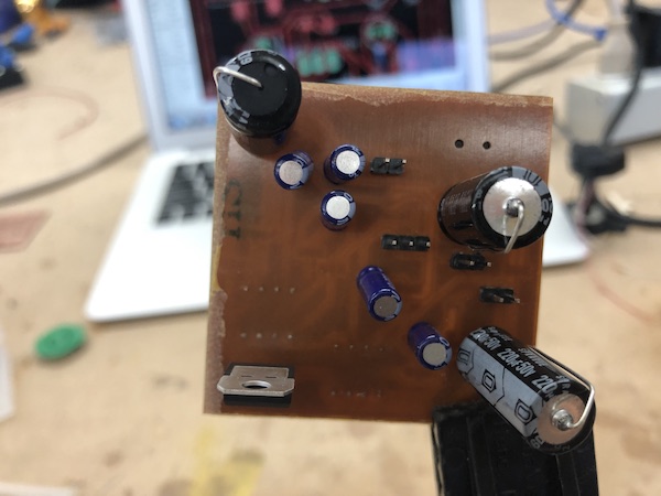
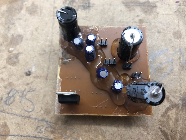
I was worried that the capacitors on the other side would move around and break traces, so I used hot glue to secure them into place.
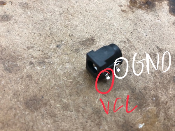
When I plugged the tonearm in and spun the record, nothing happened. I eventually realized it was because of how I oriented my power jack. I made a note earlier about how the power jack (the one that’s in the Fab Lab inventory) should be oriented, and what is power and ground:
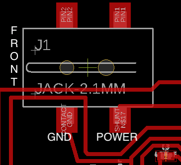
On my schematic, I had it the other way around:
During this troubleshooting process, I realized that I really didn’t need much of what was on the schematic. I had already eliminated the motor and autostop, but I could also eliminate the voltage regulatorm (LD1117) and directly give lower voltage to the preamp (LM386). I emailed Zach about what kind of power he was supplying with his power jack, and he said that he was using a 12V AC/DC adaptor. Looking at the schematic, the motor (which uses a lot of voltage because it’s a motor) receives unregulated voltage from the power jack. Then, the voltage regulator is between the power jack and the two amplifiers.
Dr. Harris also informed me that I could just use mono stereo to make my life easier. This means that I would only amplify the left signal (usually white colored when looking at RCA cables).
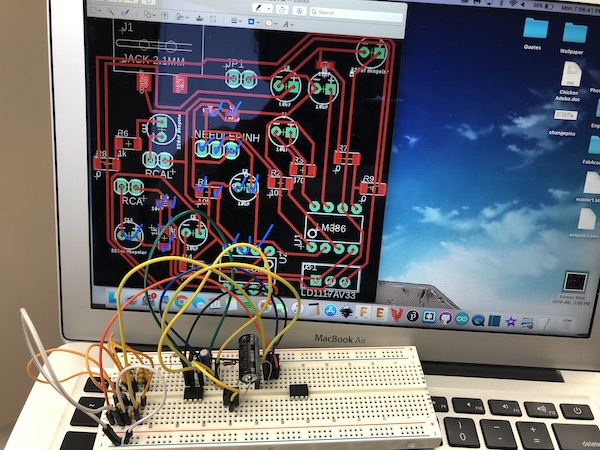
At this point, I just made a breadboard of the design I had used and tried to see if it worked. I just included the left signal as Dr. Harris suggested. It didn’t work.
During this process of making the breadboard, I did learn about capacitors. For some of the capacitors that I needed, the lab didn’t have through hole components of the right value. So, I took a through hole capacitor kit and put capacitors in series to build the right capacitance. For example, I needed a 470nf capacitor, so I used four 100nf capacitors, one 47nf capacitor, and two 10nf capacitors in parallel, which gave me 467nf.
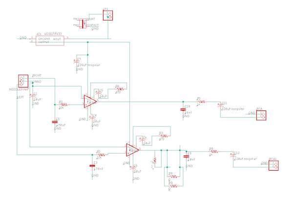
Amp Board V2.1
Dr. Harris helped me combine the schematic I was using from Zach with another. We referenced this page which very clearly and simply explained the pinout of the LM386 amplifier.
Some notes about the differences/similarities between boards 1 and 2:
-
In the first schematic, only pin 4 was going directly to ground. Pin 2 had a capacitor and then went to ground. In Board 2, both pins 2 and 4 go directly to ground.
-
Board 2 didn’t include the voltage regulator at all. It was powered by an FTDI (5V).
-
In board 1, it had both a 10k ohm resistor and a 47nf capacitor between the audio input and pin 3. In board 2, it only had a 10nf capacitor.
-
Pins 1, 4, 5, 7, and 8 were all the same.
Here’s the schematic:
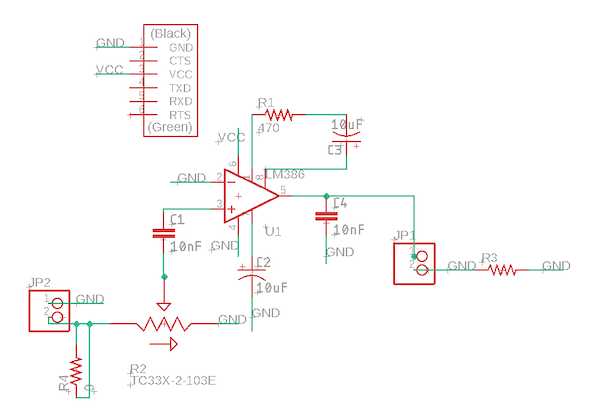
I tested it on the breadboard and it worked!
Board:
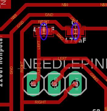
Will was using the same potentiometer and gave me the tip that, if there’s any copper (whether it’s a trace or just leftover copper) underneath the potentiometer, it would cause problems. He advised me to use a higher clearance when I milled the board in Bantam. I forgot to do so, so I had to take an X-acto knife and cut out the space underneath the potentiometer. Also, when I was routing, I made sure that no traces passed underneath the potentiometer.
Final board, plugged in:
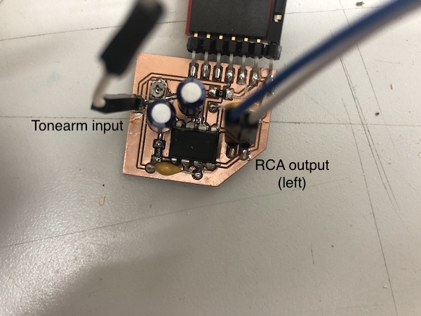
Since the breadboard worked, I was quite confident that the milled board would work, and it did!
Motor Board
As I mentioned above, I used the same exact board that I made in Week 16. I had to change my code, however, because the code I used in Week 16 (minus all of the Interfacing code) didn’t give my stepper enough torque to pull eveything along. It would try to pull everything, but the weight of it was too much to bear. Mr. Rudolph told me that this stepper motor that I was using (28BYJ-48) should be strong enough, but I was just using code that wasn’t maximizing its capabilities. So, I abandoned the code I used in week 16 (it used the Arduino stepper motor library) and went back to my Outputs week (week 12) code. I uploaded the original outputs week code I had on there, and 1. it was really slow and 2. It turned the record the wrong way.
My original code was from this Github page. I altered it slightly in Week 12 for outputs, and here are the alterations I made this week:
I fixed the speed by editing the delay in the code. Instead of using the normal Arduino delay function (in milliseconds), I had to use Arduino microsecond delay, which I learned about on the Arduino reference page. I went from a 1 millisecond delay to a 400 microsecond delay. The delay is in void (loop).
To change the direction of the motor so that the record would spin the right way, I changed the last bit of code. It went from:
step_number++;
  if(step_number > 3){
    step_number = 0;
to
step_number--;
  if(step_number < 0){
    step_number = 3;
This basically changed the order in which the steps were made. Instead of counting up the order of steps, it counts down. In the first piece of code, when the step_number variable hits 3, it returns back to zero. In my altered piece of code, when step_number reaches 0, it returns back up to 3. It continues in this cycle, stepping the stepper motor.
Here’s the full code:
#define STEPPER_PIN_1 2
#define STEPPER_PIN_2 3
#define STEPPER_PIN_3 4
#define STEPPER_PIN_4 5
int step_number = 0;

void setup() {
pinMode(STEPPER_PIN_1, OUTPUT);
pinMode(STEPPER_PIN_2, OUTPUT);
pinMode(STEPPER_PIN_3, OUTPUT);
pinMode(STEPPER_PIN_4, OUTPUT);
}

void loop() {
  OneStep(false);
  delayMicroseconds(400);
}


void OneStep(bool dir){
    if(dir){
switch(step_number){
  case 0:
  digitalWrite(STEPPER_PIN_1, HIGH);
  digitalWrite(STEPPER_PIN_2, LOW);
  digitalWrite(STEPPER_PIN_3, LOW);
  digitalWrite(STEPPER_PIN_4, LOW);
  break;
  case 1:
  digitalWrite(STEPPER_PIN_1, LOW);
  digitalWrite(STEPPER_PIN_2, HIGH);
  digitalWrite(STEPPER_PIN_3, LOW);
  digitalWrite(STEPPER_PIN_4, LOW);
  break;
  case 2:
  digitalWrite(STEPPER_PIN_1, LOW);
  digitalWrite(STEPPER_PIN_2, LOW);
  digitalWrite(STEPPER_PIN_3, HIGH);
  digitalWrite(STEPPER_PIN_4, LOW);
  break;
  case 3:
  digitalWrite(STEPPER_PIN_1, LOW);
  digitalWrite(STEPPER_PIN_2, LOW);
  digitalWrite(STEPPER_PIN_3, LOW);
  digitalWrite(STEPPER_PIN_4, HIGH);
  break;
}
  }else{
    switch(step_number){
  case 0:
  digitalWrite(STEPPER_PIN_1, LOW);
  digitalWrite(STEPPER_PIN_2, LOW);
  digitalWrite(STEPPER_PIN_3, LOW);
  digitalWrite(STEPPER_PIN_4, HIGH);
  break;
  case 1:
  digitalWrite(STEPPER_PIN_1, LOW);
  digitalWrite(STEPPER_PIN_2, LOW);
  digitalWrite(STEPPER_PIN_3, HIGH);
  digitalWrite(STEPPER_PIN_4, LOW);
  break;
  case 2:
  digitalWrite(STEPPER_PIN_1, LOW);
  digitalWrite(STEPPER_PIN_2, HIGH);
  digitalWrite(STEPPER_PIN_3, LOW);
  digitalWrite(STEPPER_PIN_4, LOW);
  break;
  case 3:
  digitalWrite(STEPPER_PIN_1, HIGH);
  digitalWrite(STEPPER_PIN_2, LOW);
  digitalWrite(STEPPER_PIN_3, LOW);
  digitalWrite(STEPPER_PIN_4, LOW);
}
  }
step_number--;
  if(step_number < 0){
    step_number = 3;
  }
}
I had to make another board as the one that I did in Week 16 because I ripped some traces. Here’s the process, in pictures (see week 16 for more detail):
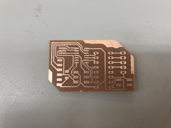
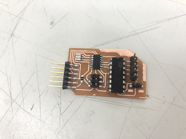
I took Kai’s advice and used higher clearance to mill my boards. It made it a lot easier to make sure that there were no shorts because of the extra copper left on the PCB.
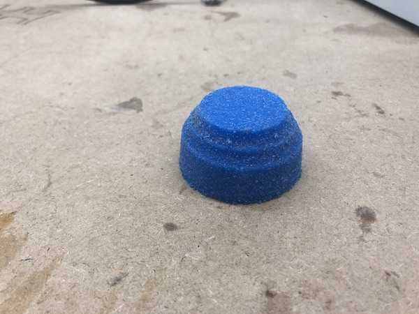
Casted Feet
I molded and casted the feet of my record player in Molding and Casting Week/Week 10. I used 3D milling (per that week’s required assignment) and made four of the same cast to create four feet.
With the 3D printed feet holders, I was able to put them onto the record player.
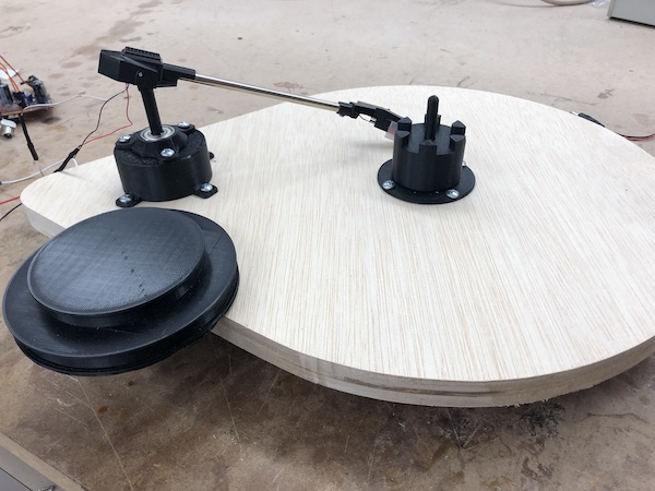
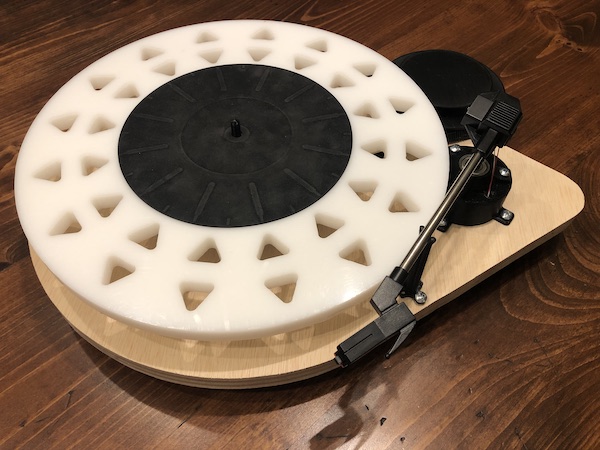
Assembly
Assembly was generally really easy because I just screwed everything on with the power screwdriver.
Feet:

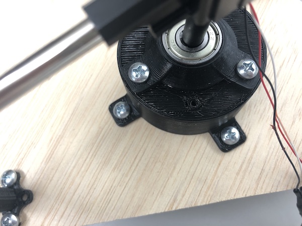
Stepper:
Spindle:
Tonearm stand:

All:
Cable Management
The wires of the tonearm were super super thin and not super strong. I needed them to fit into a female header cable so that I could use a male to female wire and plug it into my amplifier board. In order to do that, I applied flux to the stripped tonearm wires. I then tinned my soldering iron and let the solder move onto the wire. Notice the difference between the red wire and the white wire. The red wire has solder applied and the white one does not.
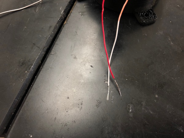
I tried plugging this into a female header, but it was still too flimsy to be plugged in. After realizing this, I wrapped the tonearm wire around the cut off ends of resistors and soldered it down. This picture shows it wrapped…
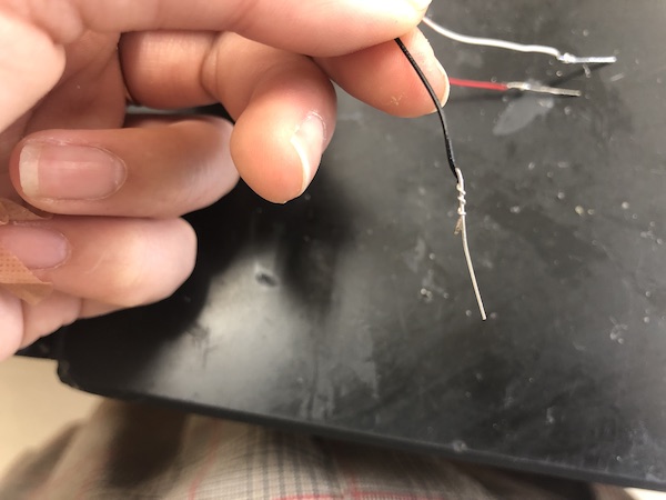
And this picture shows all of the wires soldered down into the resistor leg ends. I plugged these into female pin headers as I described.
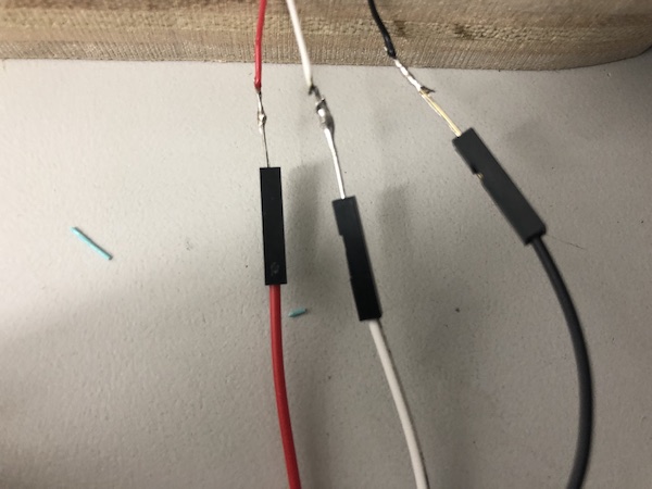
If the tonearm wires weren’t so thin, I would’ve made my own female pin headers off of it. However, it was so thin that it didn’t really work when I tried to use the crimps and such to create a female end.
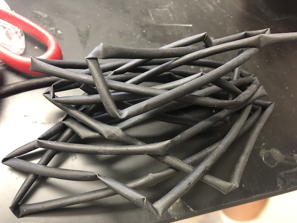
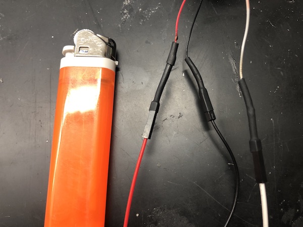
Once I had the female pin headers attached, I used heat shrink to cover up my cables. I learned how to use a lighter to do this! I almost (and probably kinda did) burned myself in this process.
I threaded these wires through the hole created in the tonearm booster (shown below once again) and then let those wires go to the underneath of the record player base.