12. Output devices
I wanted my output device to be a motor since I need to use a motor in my final project. I may not necessarily use this exact motor for my final project, but doing a motor for this week will help me understand them overall.
Research
Since we have it right here in the lab, I used the 28BYJ-48 stepper motor:
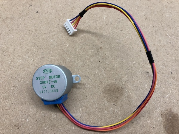
I referenced this video to understand the motor. I learned that:
- This motor has 2048 steps per revolution
- Minimum of 2 milliseconds between steps
- Maximum speed of 500 steps per second
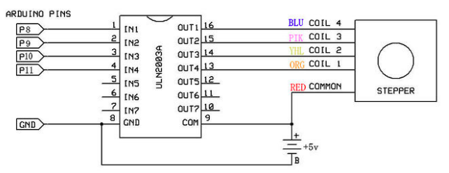
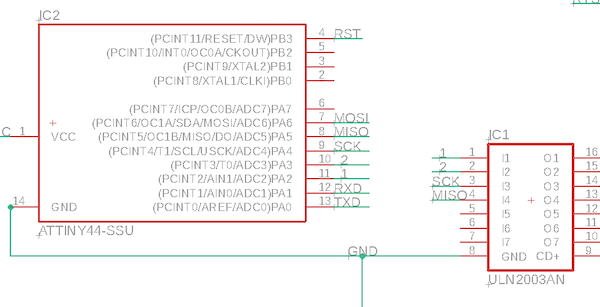
I found this schematic of the ULN2003 board that came with the motor. It is the driver.
ULN2003:
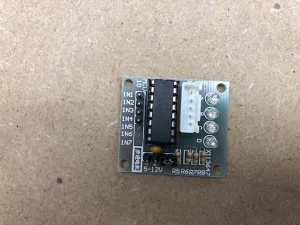
Schematic:
Eagle
ULN-2003 footprint
First, I had to download the footprint of the ULN2003. I found the footprint here. I had to sign up with SnapEDA to download it, but here’s the download of the footprint
After finding this library, I just found a library in the Eagle Library Manager. I just decided to use this library, the uln-udn library, made by librarian@cadsoft.de. It’s full of drivers.
Schematic and Board
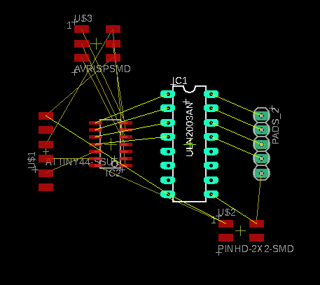
Using the schematic that I included above, I essentially used the existing schematic of the driver board that I had. Instead of hooking up to an Arduino, I used an ATtiny 44 on the board. Here’s the schematic again:
My schematic:
Don’t download my bad schematic (.sch) files
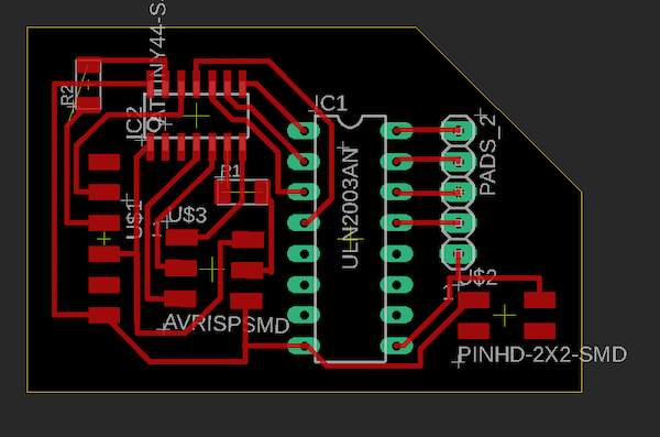
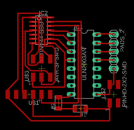
Board:
Don’t download my bad board (.brd) files
I ended up changing the schematic and board later on; keep reading to see how and why.
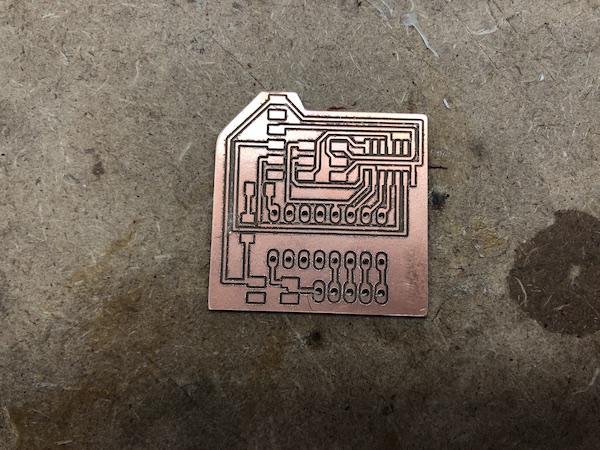
Milling
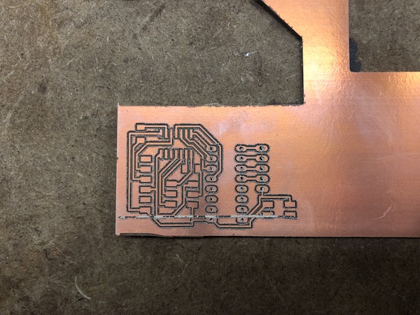
I originally tried to mill two boards, but when I ran the traces, I forgot to re-home the machine. So, when the first trace ran, it cut right through the board:
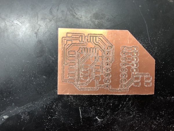
Here’s the board that did work, V1.1:
Note on the Nomenclature of Boards
I had so many different boards that I made this week. To be clear about what board I’m referencing, refer to the name of the section it’s in.
Versions of boards are differentiated by the design file. If the design / Eagle files are the same, then two boards are the same version. It is the number one in V1.2. In all, I had two versions of my output week boards.
Iterations of boards refers to the physical board that is milled and soldered. It is the number two in V1.2.
Board V1.1
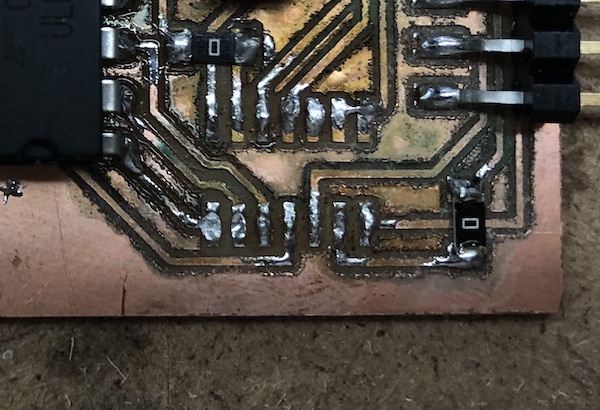
When I soldered board V1.1, I decided to use a driver socket. However, I soldered it on the bottom so that it would be easier to solder. After doing this, I realized that soldering it upside down would mess up the connections. I abandoned this board.
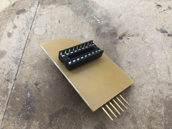
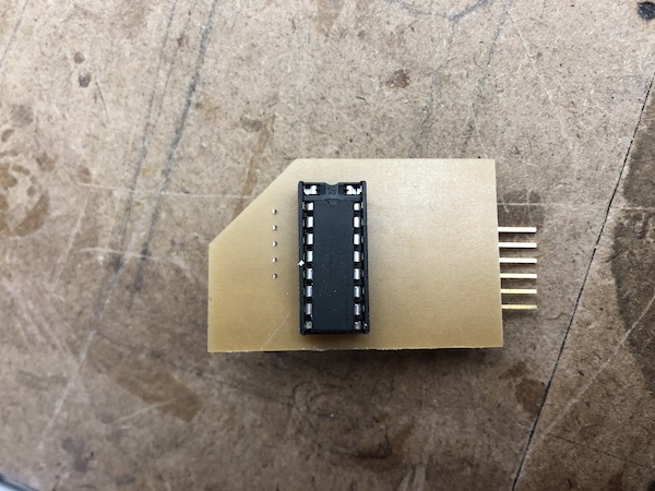
As I was soldering, I had such a difficult time with through hole soldering (I shouldn’t have soldered it like I did, but I did). I realized after a long while that I was using surface mount soldering techniques while trying to through hole solder; I put some solder on the tip of the soldering iron and tried to put it down. For through hole, I should have been applying solder by holding the solder in one hand and the soldering iron in the other. I figured this out when I soldered the second row of the socket, as seen in my terrible soldering job on one side and decent one on the other. Apparently, I totally forgot how to through hole solder after soley surface mount soldering for Fab Academy.
Takeaways
I learned a bunch of things while I was soldering, including:
- How to through hole solder (again, because I somehow forgot)
- That FTDI headers are easier to solder in pin holes since they are bent (and the plastic of the pin isn’t in the way as much as a normal pin)
- Paste flux really helps when soldering through hole components onto a one sided PCB board. I used the smallest touch of paste flux at the base of the pin and it made the soldering process really easy.
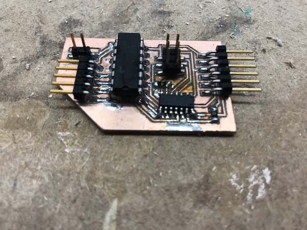
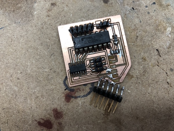
New Board, V1.2
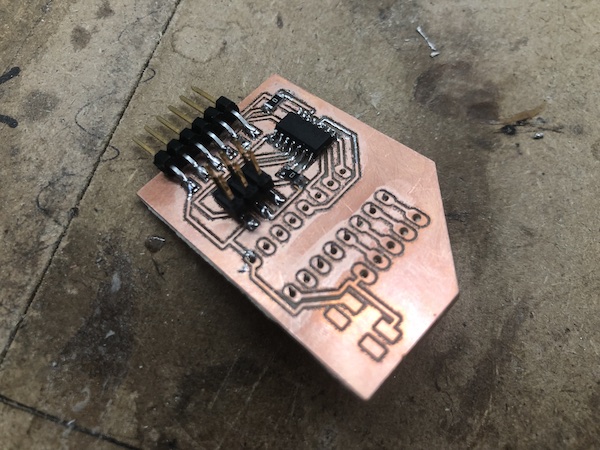
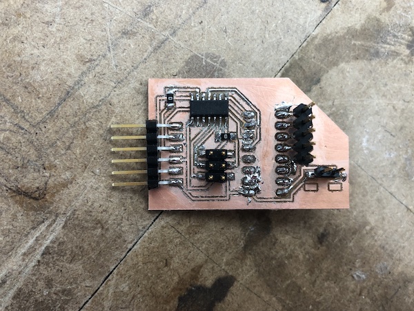
I milled another board (using the same Eagle files) and started again. Here’s the 2nd board soldered:
Code
Since the use of driver that I had originally (and referenced in creating my board) is quite widespread, there was a lot of code online. I watched a Youtube video on it, and it had some code on GitHub accompanying it. I changed the pins (pins that were supposed to be used on the Arduino) so that they matched the pins that I was using on the ATtiny44.
This:
#define STEPPER_PIN_1 9
#define STEPPER_PIN_2 10
#define STEPPER_PIN_3 11
#define STEPPER_PIN_4 12
Turned to:
#define STEPPER_PIN_1 2
#define STEPPER_PIN_2 3
#define STEPPER_PIN_3 4
#define STEPPER_PIN_4 5
The first time I uploaded the code to board V1.2, I think I bricked it because I forgot to change the Board, Processor, and Clock settings. Specifically, I think that the incorrect clock settings bricked my board (it was set to the settings for the Hello World Board with the external 20 MHz resonator).
Troubleshooting, Board V1.2
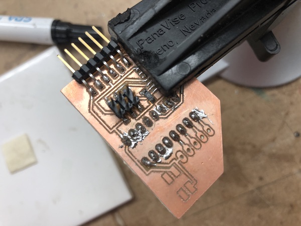
In order to remove the bricked ATtiny on board V1.2, I used the reflow gun for the first time!
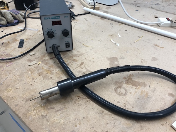
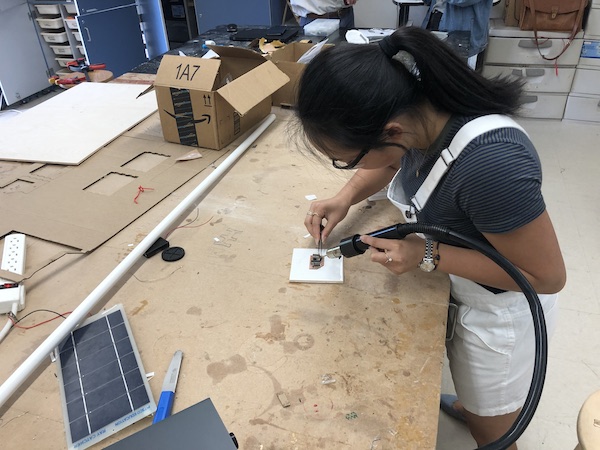
It basically spits out hot air (400 degrees C) to melt the solder in a general area at once. It is extremely useful for removing components with several soldered parts, like pin headers or chips.
Here’s what it looked like after using the reflow gun:
I’m dumb
Then, since I was dumb, I didn’t use a desoldering braid or anything to remove the solder that remained on board V1.2. I just tried to solder another ATtiny on top of the existing solder, which really just didn’t work.
Then, since I was dumb again, I gave up on board V1.2 when I really could have just used the reflow gun to remove the ATtiny again and use a desoldering braid to get rid of the excess solder.
New board, V1.3
I milled a new board, and soldering went quite smoothly after struggling with soldering on boards V1.1 and V1.2. However, I then proceeeded to rip the pin headers that would be connected to the stepper motor. Mr. Taylor helped me try to save the board, but it didn’t really work. I abandoned this board.
New board, V1.4
I milled and soldered yet another board.
Programming / Troubleshooting, Board V1.4
When I uploaded the code to board V1.4, it gave me this error:
avrdude: Error: Could not find USBtiny device (0x1781/0xc9f)
To eliminate any possible errors with soldering, I used a multimeter to ensure that the pins of the ATtiny 44 weren’t connected. Then, I used the multimeter to make sure that the pins of the ATtiny that should be connected to the FTDI/pin header were connected, referencing my .brd files as I went. Everything was in order; it didn’t seem to be a hardware issue.
Then, I looked up the error and found on this Arduino reference page that the bootloader wasnt’ active. So, I tried to burn the bootloader and got this error:
avrdude: Error: Could not find USBtiny device (0x1781/0xc9f)
Error while burning bootloader.
This presented a problem, as it seemed to be a circular issue. The code couldn’t upload because the bootloader isn’t activated, but I couldn’t activate the bootlader because Arduino couldn’t find it in the first place.
I asked Mr. Rudolph, and he said that this error was not referring to the ATtiny 44 like I thought it was; it was referencing an error with the programmer. So, I borrowed Will’s programmer. I have already run through my three programmers that I originally made, so I will mill two new ones soon so I don’t have to borrow other people’s programmers.
I met with Dr. Harris, after getting the Will’s programmer, and Arduino was giving me the error message that the connections were incorrect. Dr. Harris informed me that my ATtiny was not hooked up properly to the FTDI, so the ATtiny couldn’t communicate with the computer.
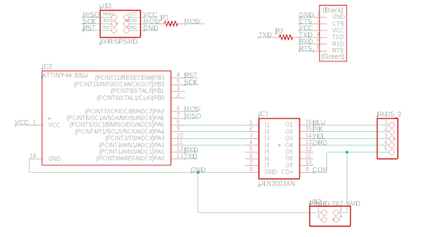
Designing New Schematic, Board V2.1
I changed the pins on the ATtiny. This time, I wanted to make sure that I knew which pins would work for what I wanted it to do. So, I made sure that the functions like MISO, MOSI, RST, TXD, RXD, and SCK were all in the right spot. As I mentioned earlier, I talked to Dr. Harris about my schematic. He said that I can double up on pins, like connecting a pin to the motor driver and also using it for an FTDI pin. Obviously, I should not do this with GND, VCC, or RST, but the other pins are apparently fair game. According to Dr. Harris, when code is being uploaded to a microcontroller / a microcontroller is being programmed, it is in a very different mode than when it is functioning normally. So, using a pin on the microcontroller to program will not affect its function when it is not being programmed.
I kept everything else the same as the previous schematic I designed, aside from the pins of the ATtiny. Here’s the new pin assignments on the ATtiny44 (and the motor driver off to the right):
Board design, V2.1:
Download my new .brd and .sch files
New Board, V2.1
I milled out the board and soldered it. When it came time to programming, I saw that the FTDI was upside down. So, I tried to plug the Sparkfun FTDI (which supplies power) in. When I did this, I ripped the traces.
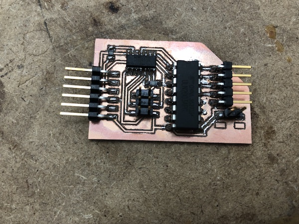
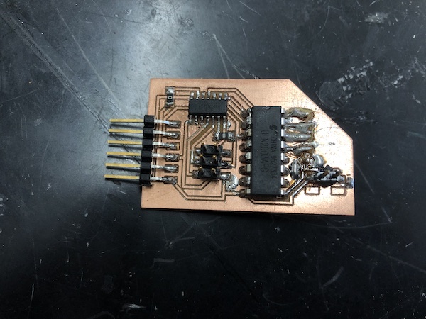
New Board, V2.2
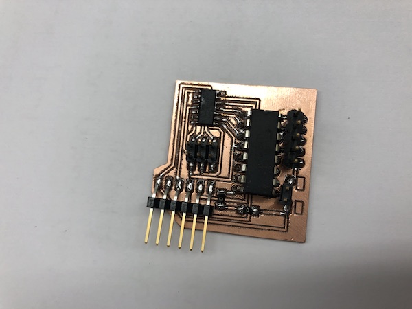
This board didn’t have any soldering or physical errors (thank GOD). Here’s how it looked like after being milled and soldered:
Wrong controller error, Board V2.2
On all of these boards, I was using an ATtiny44. When I uploaded the code (discussed above), the Arduino spit back that I was using the wrong board. I had already changed all of the settings to fit the ATtiny44 in Arduino, but it was still giving me this error. I looked on this forum and it suggested that my wiring may be wrong.
Then, I changed the settings so Arduino would give me the verbose output when uploading and compiling. Here’s one of the lines that I thought was particularly interesting:
avrdude: Device signature = 0x1e9206 (probably t45)
It seemed to think that I was using a 45, which I was not.
Then, I tried to upload the code to an existing, functioning board that I had with the ATtiny44 (the Hello World board that we made in week 7). It was really weird because, when I did this, Arduino still gave me the same error, saying that I was using an ATtiny45.
I went onto a different computer (a Windows that we have in the FabLab) and tried from there, but Arduino still said that I was using an ATtiny44.
Just as a hunch, I thought that maybe the fact that I was using the Sparkfun Tiny AVR programmer was messing it up. I knew that the Hello World board from week 7 worked, so it was super weird that neither could upload. The commonality between these two instances was the programmer. So, Mr. Taylor gave me an extra programmer he had (he made it for practice during week 5). When I used this programmer, the code uploaded wonderfully!
Setup, Board V2.2
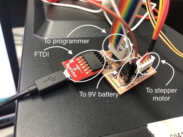
Once I successfully uploaded the code, I plugged everything else in, and I had quite an elaborate setup for this board. I had the following connected to my board:
- Sparkfun FTDI (as always)
- Programmer (as always)
- 9V battery, female to male wires > alligator wires > battery connector > 9V battery
- Stepper motor
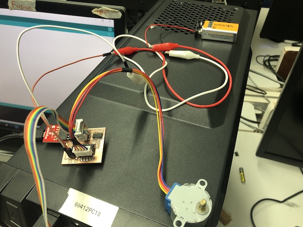
At first, nothing happened. Before I freaked out about having to make yet another board for this week (I had made maybe 6 by this point), I checked the battery. I was using a 9V battery, but using multimeter, I saw that it only had around 5V left in it. I searched around until I found a battery that actually had 9V. When I plugged this battery in, it was successful and the stepper motor rotated!
Functioning Board V2.2
In the video, you’ll see that the little tape flag pauses at some points. This is only because the tape was quite long and was getting caught on the protrusions of the stepper motor.
This week was a huge pain; I literally made two different versions of this board and several iterations of each version. I think I came out to having created 6 boards. (V1.1,2,3,4 and V2.1,2).