6. 3D Scanning and printing
I started this week using the scanner.
3D Scanner
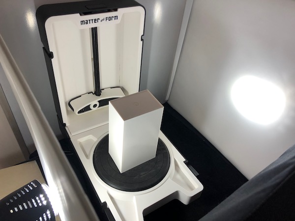
We used Matter and Form as a 3D scanner. I read the manual.
To set up, since we didn’t want any background movement as we moved around in the lab confusing the scanner, we used the photobox to surround it and isolate it.

Calibration
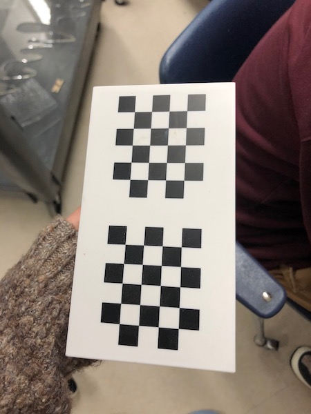
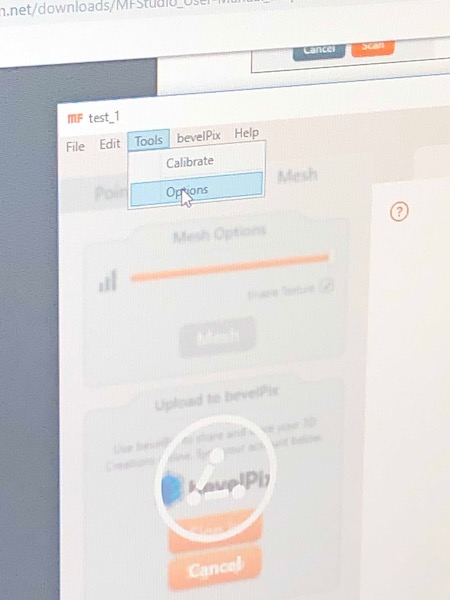
Before running the scan, I wanted to calibrate it to make sure that my scan (which would likely take at least an hour) would work properly. I used the calibration block, not the sheet.
Underneath Tools, I selected Calibrate.
A time-lapse of it calibrating:
Scan
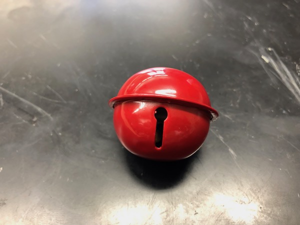
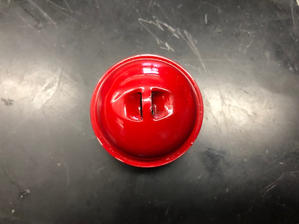
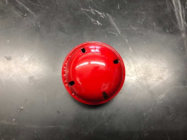
I decided to scan this bell that I found around the school.
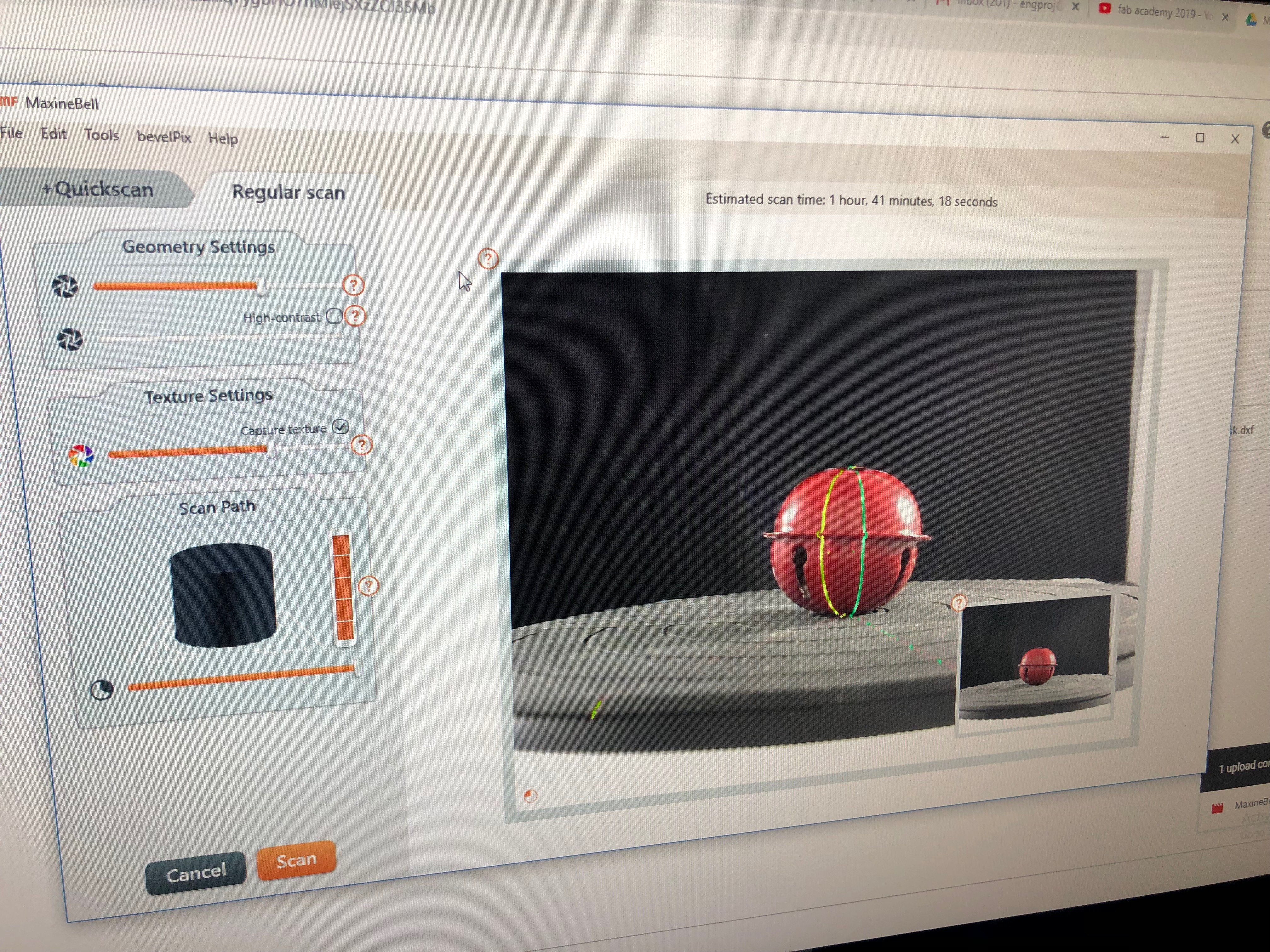
I created a new scan and used Regular Scan, which takes longer but is more detailed. I adjusted the Geometry Settings, which are the settings of the lasers. I ensured that the laser was clear, minimizing noise. This picture also shows the settings I used.

I pressed Scan and let it run. It took way longer than Matter and Form predicted.
A screen record of the scan (20x):
A picture and video of what it looked like at the end of the first scan:
I wanted to do several scans so that the scan is as accurate as possible. To achieve this, I installed VNC Viewer on my personal computer. This allowed me to control the computer connected to the Matter and Form scanner (which is in the FabLab) from my laptop at home. The scans took a lot more time than I was able to stay at the FabLab, so this viewer was super helpful.
Others advised me that the 3D scanner program would be able to identify the object even if I rotated it (and therefore giving the scanner a better view of other angles, like the top of the bell). When I did try to scan the bell at different angles, Matter and Form did not recognize the different angles. So, I removed visibility from that final scan that used different angles and just worked with what I had from one angle.
The mess of having multiple angles:
Cleaning
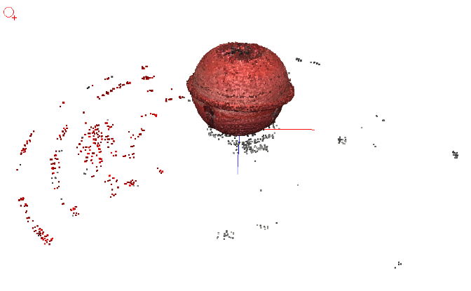
After scanning, there were a lot of points that I had to clean up. I used the various cleaning tools to achieve a clear point cloud.
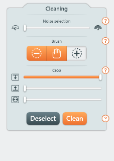
Going from top to bottom in the tool bar:
Noise Selection helps select points that are noisy, or off from the actual object. I used this tool sparingly; if I used this tool too much, I could have removed some of the actual points that I would have wanted from the point cloud.
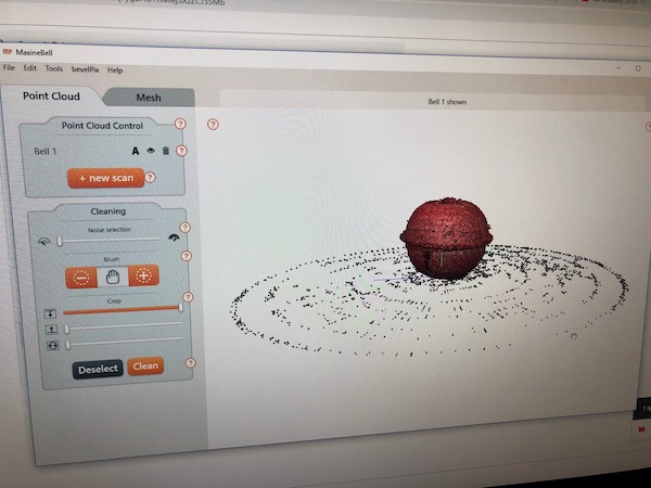
Brush tool was extremely useful. Using the cursor, I individually picked out points that were off. Red points indicates that they are selected. After I selected the points I wanted to remove, I pressed Clean, and they were deleted from the point cloud.
Crop from the top does as the name implies. Since I had a very small object, I used this tool to the furthest extent and removed points from the higher section of the scanner.
Crop from the bottom also does as its name implies. I did not use this tool, since my object sat right on the turntable. Cropping from the bottom would remove points from the bell.
Crop from the center was not extremely helpful for my specific object. I did not use this tool at all.
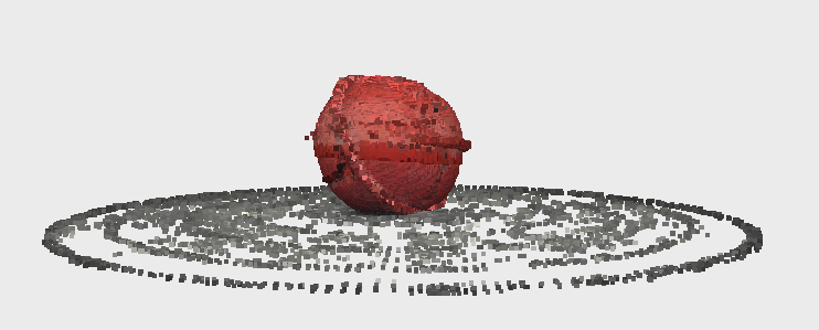
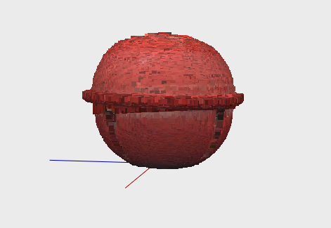
The final point cloud:
Mesh
Once I cleaned up the point cloud, I went to Mesh, which is the second tab at the top of the page. I played around with different detail levels and clicked on Enable Texture so that the cutouts in the bell could be seen.
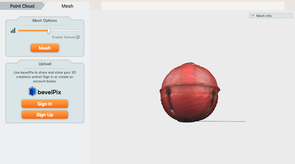
Since I did not get any good angles of the top of the bell, the top is largely distorted.
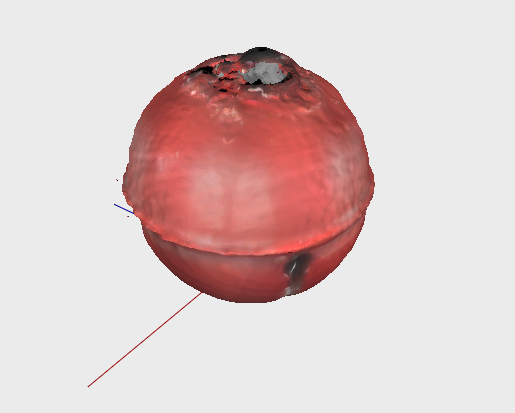
Views of the final mesh:
Download my Matter and Form file
Final Thoughts
If I were to do this again, I would set the bell at a better angle so that the scanner could capture it better, like setting the bell at a slight angle instead of straight up and down.
3D Print
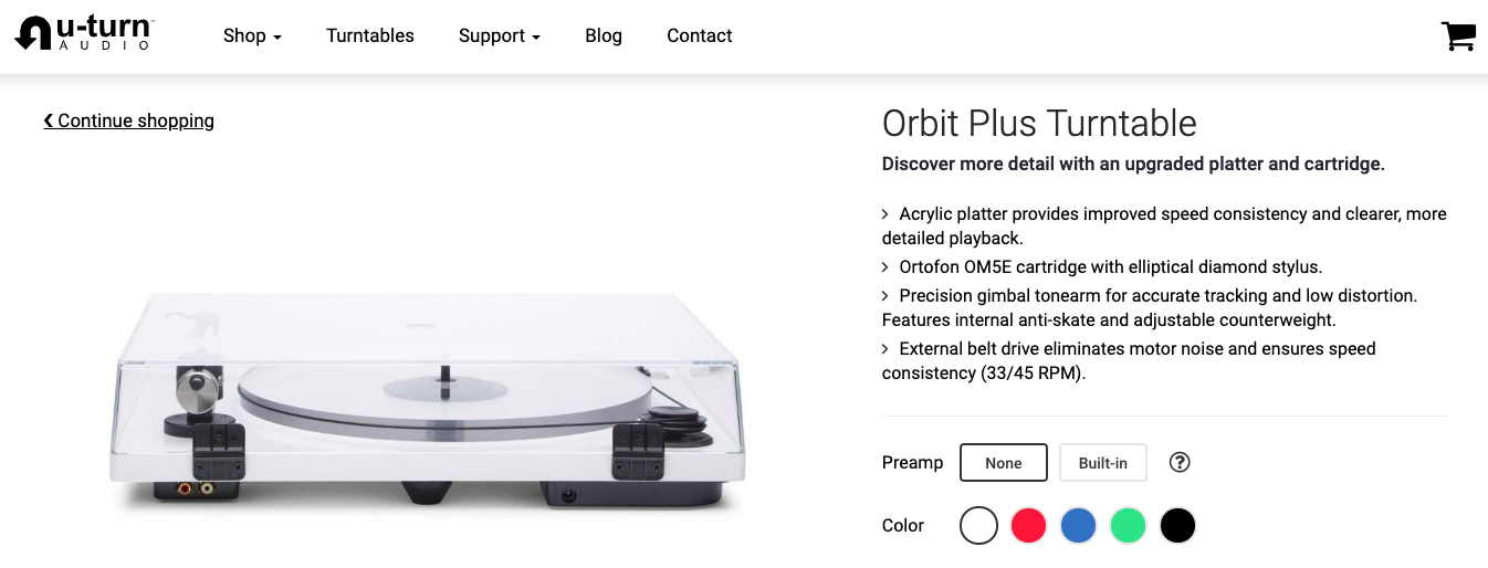
I decided that I wanted to print a hinge so that, if I wanted to make a lid for the record player that lifted up and down, I could.
Hinge from video
I watched this video. First, I followed this tutorial loosely and printed it. Then, I would apply what I learned to make my own hinge. I very loosely followed the tutorial, not using the measurements he stated. Instead, I simply followed the shapes the video used.
I wanted to make sure that my measurements I was using enabled the hinge to actually be functional before I went and designed my own hinge.
My original sketch:
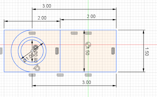
I extruded it out 0.5 cm. I copy pasted the original sketch so that I could make sketches on the outermost face of the newly extruded shapes. I extruded various parts, trying to get the proper hinge shape.
Halfway extruded:
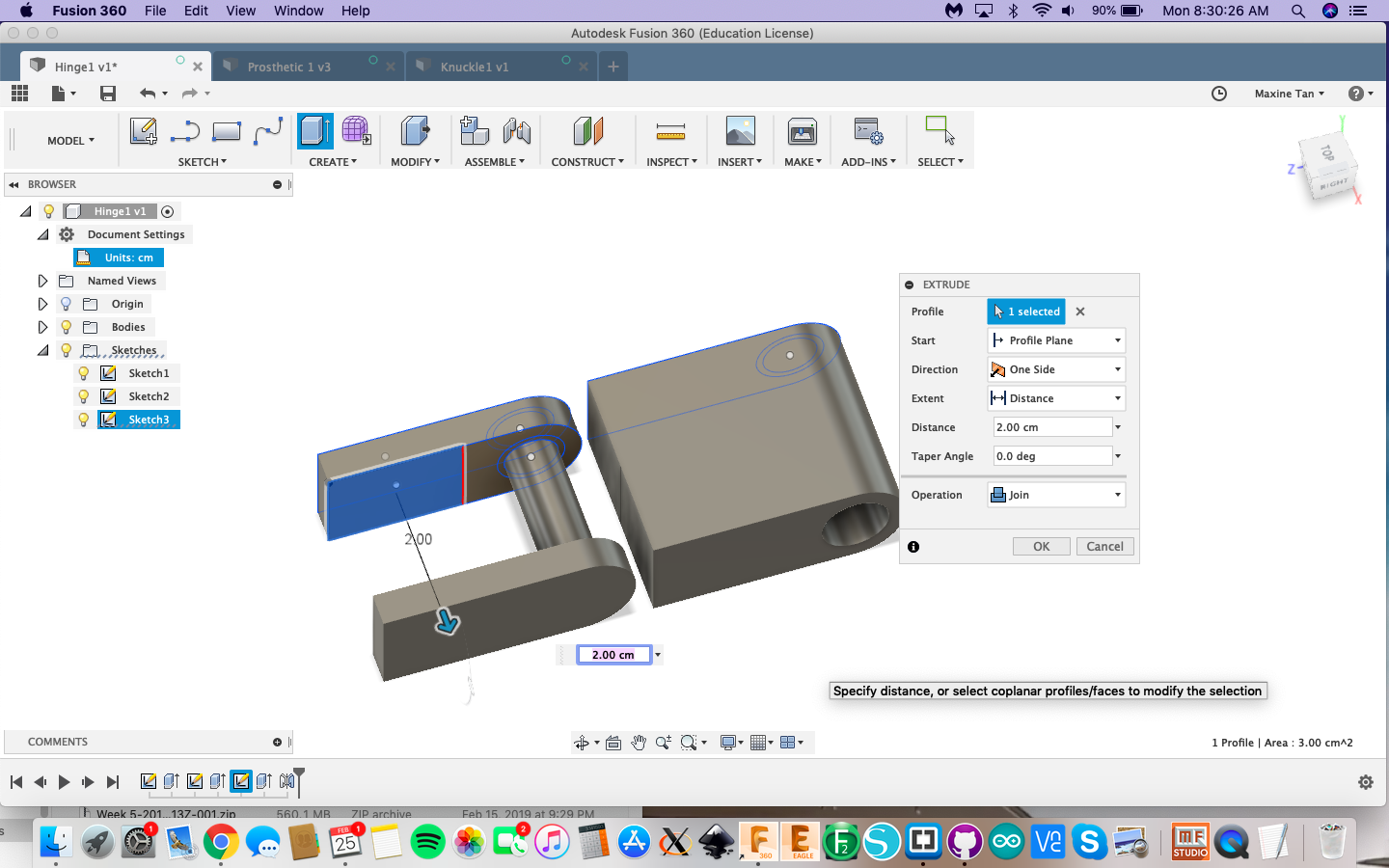
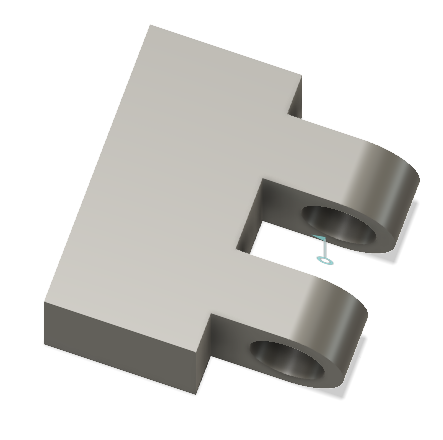
Completing one half of the hinge:
I repeated the various extrudes on a different sketch moved over to the side a bit, forming the other half of the hinge.
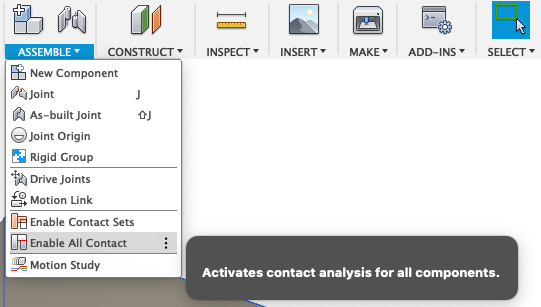
Once I had both bodies, I used a Joint.
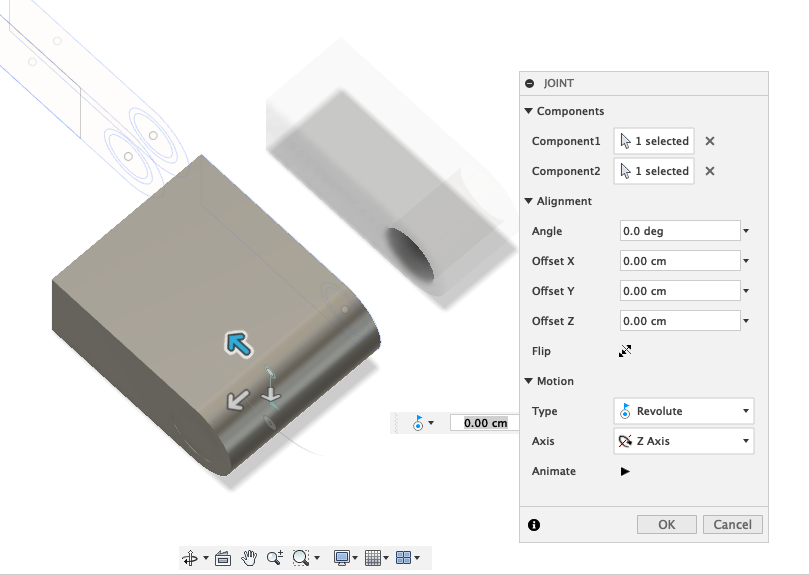
I selected the center of the cylinder as where the Joint would occur and set it to a Revolute joint.
Hinge 1:
My Hinge
Fusion 360 Design
Using many of the skills I already know (like my CAD knowledge from Week 3and the basic idea and steps of the earlier hinge, I made a double hinge.
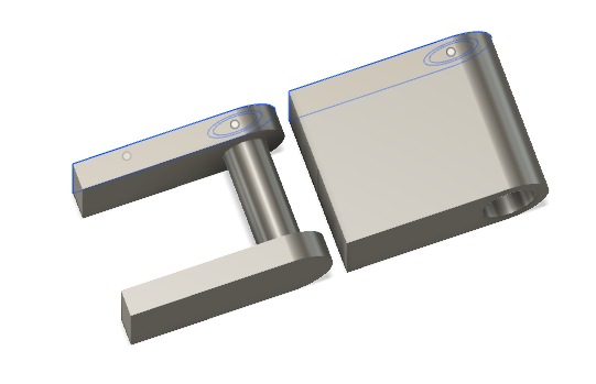
The two separated parts of my hinge:

After the fact, I realized that I could have just made one half of the hinge and used the Mirror tool to reflect it over an offset plane. However, I did not think of this as I was making it because I was unsure about how many tabs of the hinge I would make. I also realized after the fact that I could’ve connected the cylinder to the inside of the middle tab. I didn’t in my design (see the space all around the cylinder in my embedded Fusion 360 file below), but that’s alright. My print wasn’t beyond the capabilities of the 3D printer, so it all worked out anyway.
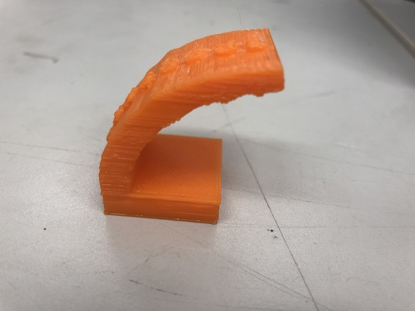
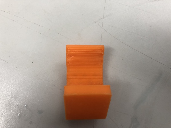
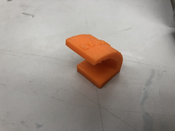
Printing my hinge:
Hinge 2 printed:
Group Project
I created my own test as well as using one that was referrenced in Neil’s discussion of tolerance tests.
Fusion 360 Design
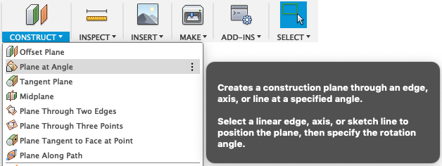
I wanted to test the ability of the 3D printer to create something at angles, especially since I was considering including an angled aspect for my personal 3D print. So, the Plane at Angle tool was critical.
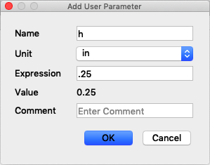
First, I created a 1in x 1in square and extruded it 0.25 inches. then, I created a rectangle on the top of that body with dimensions of 0.25in x 1in. I extruded that smaller rectangle up 0.25 inches. At this point, I realized that I would need a User Parametric with a value of 0.25 in case I wanted to change that measurement in the future, so I created it and called it h.
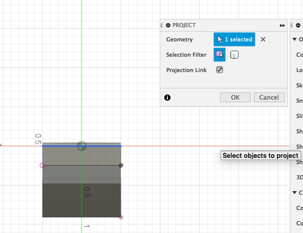
Using the Plane at Angle tool, I created planes at increasing angles, from 10 degrees until 80. I continuously made new sketches on the planes at differing angles, using the Project tool to make sure each rectangle lined up with the previous level’s rectangle.
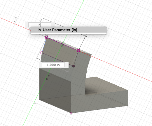
In the photo above, I used the h parameter to form the triangle.
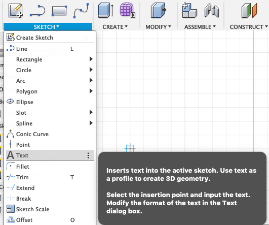
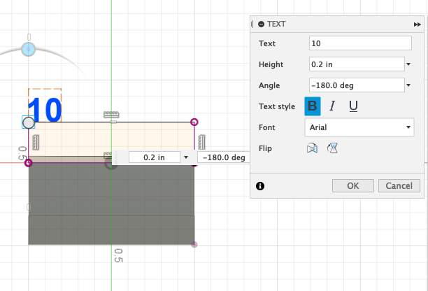
To label the levels’ angles, I used the Text tool and extruded the text 0.05 inches away from the surface.
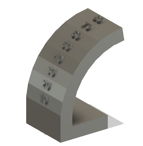
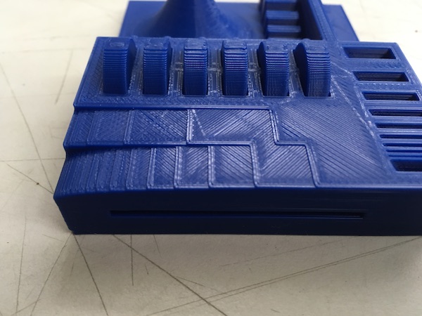
In the end, this is what it looked like:
Printing
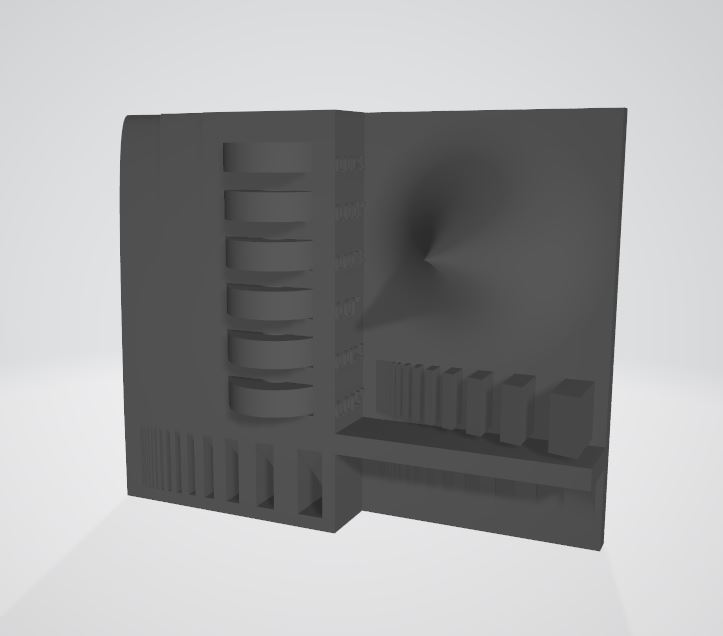
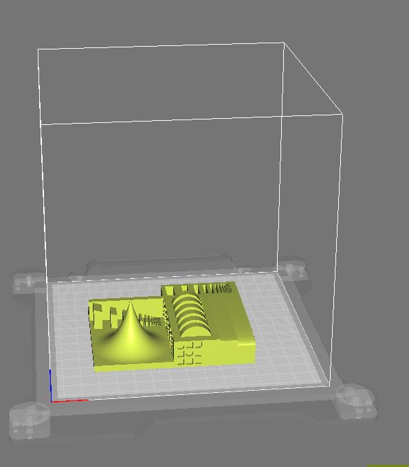
The test print file:
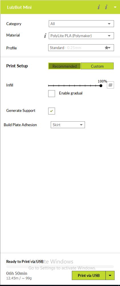
We decided to do several prints of the test file: PLA and 20% infill, PLA with 100% infill, and ABS with 20% infill. All except the PLA with 20% infill failed. We used Cura to load our files into the printer.
Settings for the 20% infill and 100% infill for PLA, respectively:
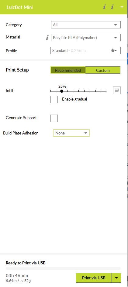
We consulted the actual spool for temperatures for the PLA prints and applied it in the settings in Cura.

For ABS, I looked up what was recommended for Lulzbot. I also made sure to indicate that my material was ABS.

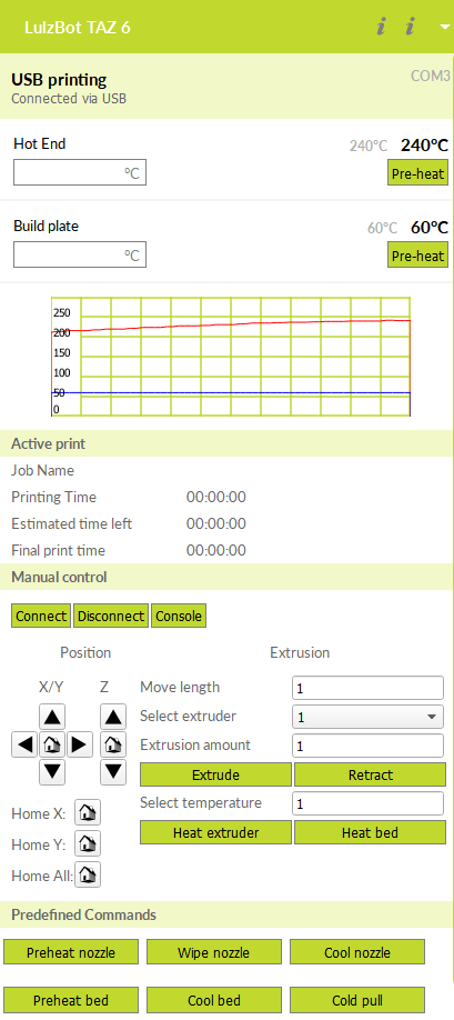
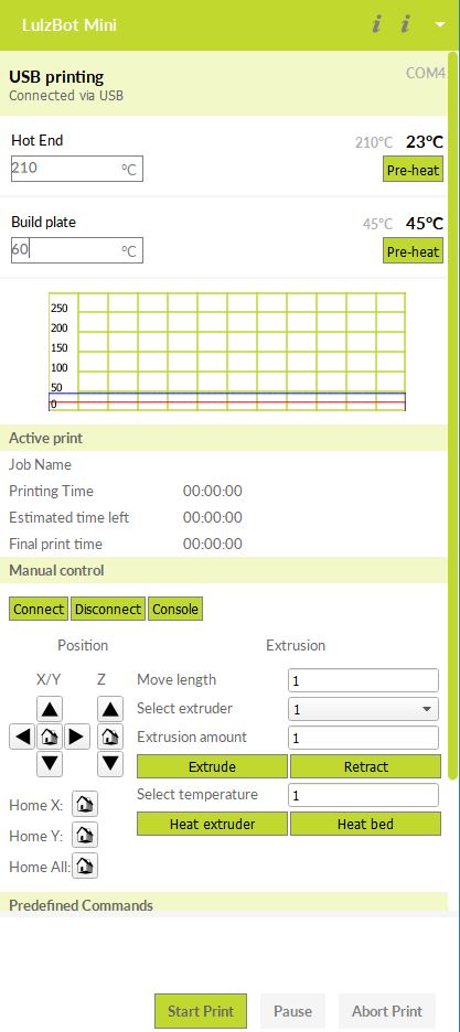
The file placed in Cura:
Fails
Both the ABS and the 100% infill PLA prints failed.
Failed ABS:
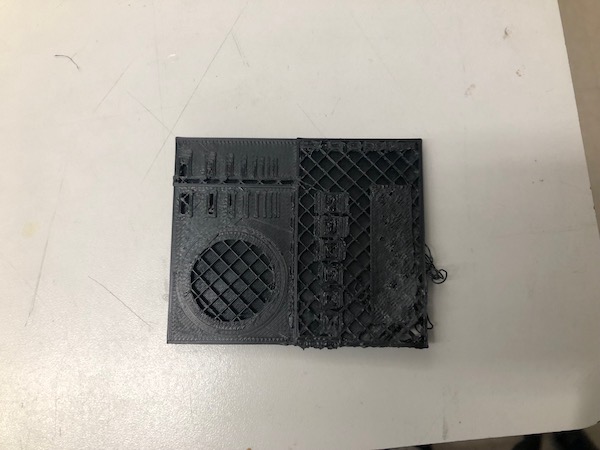
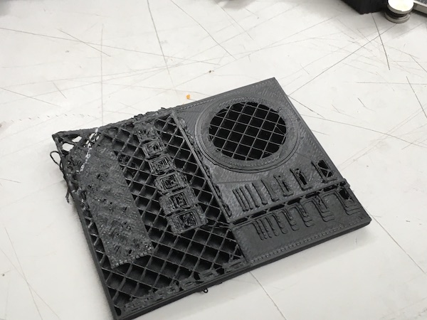
Failed PLA, 100%:
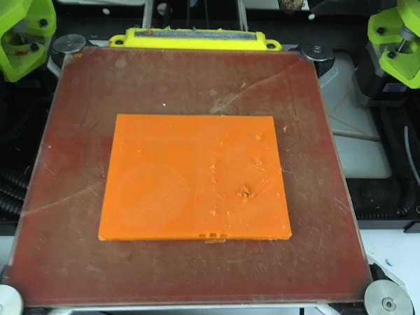
It simply stopped extruding as it should have.
Successful Print
The PLA with 20% infill print was successful!
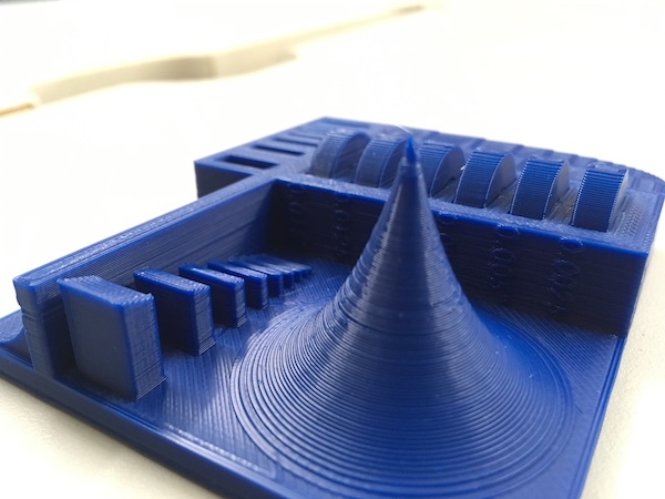
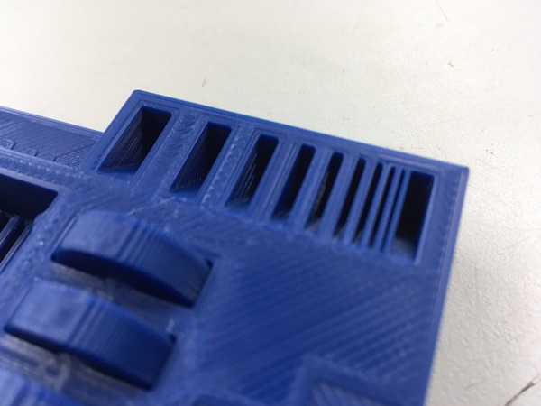
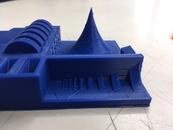
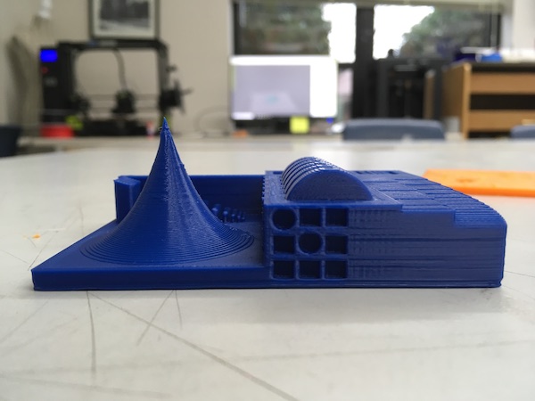
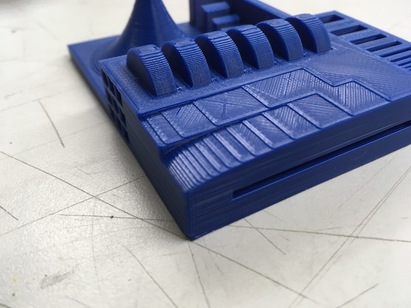

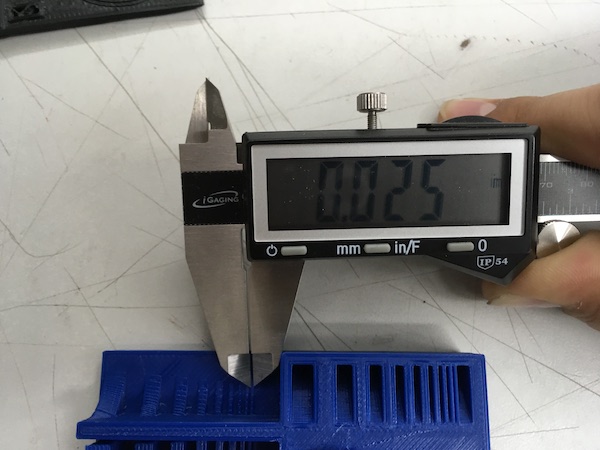
Measurements:
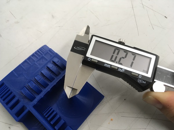
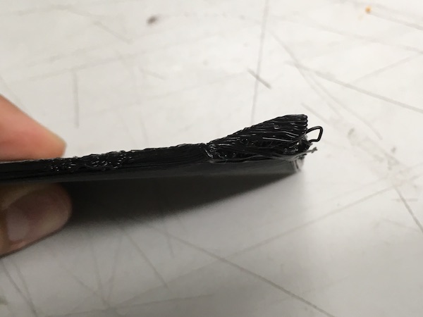
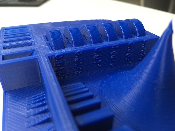
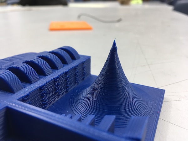
Closeup of the tip:
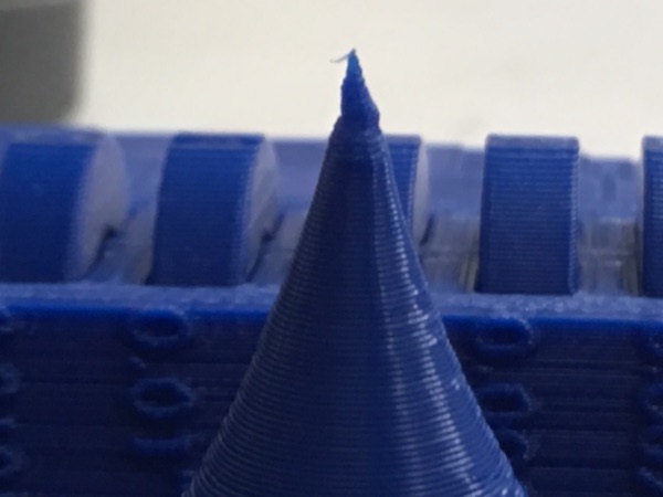
The thinnest strip that was printed was 0.25mm, and the thinnest part of the tip was 0.27mm.
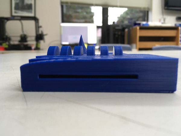
Successful Overhang Test